2001 NISSAN ALMERA TINO tow
[x] Cancel search: towPage 558 of 3051
SEF553Y
JEF096Y
SEF097Y
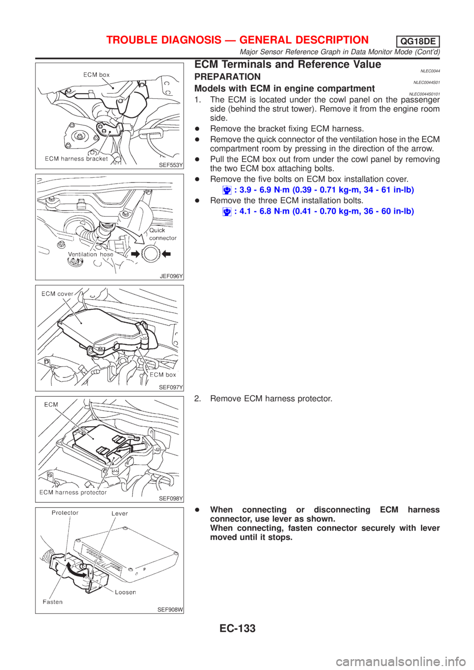
ECM Terminals and Reference ValueNLEC0044PREPARATIONNLEC0044S01Models with ECM in engine compartmentNLEC0044S01011. The ECM is located under the cowl panel on the passenger
side (behind the strut tower). Remove it from the engine room
side.
+Remove the bracket fixing ECM harness.
+Remove the quick connector of the ventilation hose in the ECM
compartment room by pressing in the direction of the arrow.
+Pull the ECM box out from under the cowl panel by removing
the two ECM box attaching bolts.
+Remove the five bolts on ECM box installation cover.
: 3.9 - 6.9 N´m (0.39 - 0.71 kg-m, 34 - 61 in-lb)
+Remove the three ECM installation bolts.
: 4.1 - 6.8 N´m (0.41 - 0.70 kg-m, 36 - 60 in-lb)
SEF098Y
2. Remove ECM harness protector.
SEF908W
+When connecting or disconnecting ECM harness
connector, use lever as shown.
When connecting, fasten connector securely with lever
moved until it stops.
TROUBLE DIAGNOSIS Ð GENERAL DESCRIPTIONQG18DE
Major Sensor Reference Graph in Data Monitor Mode (Cont'd)
EC-133
Page 1036 of 3051
![NISSAN ALMERA TINO 2001 Service Repair Manual Freeze frame data
item*Description
B/FUEL SCHDL [msec]+The base fuel schedule at the moment a malfunction is detected is displayed.
INT/A TEMP SE [ÉC]
or [ÉF]+The intake air temperature at the momen NISSAN ALMERA TINO 2001 Service Repair Manual Freeze frame data
item*Description
B/FUEL SCHDL [msec]+The base fuel schedule at the moment a malfunction is detected is displayed.
INT/A TEMP SE [ÉC]
or [ÉF]+The intake air temperature at the momen](/manual-img/5/57352/w960_57352-1035.png)
Freeze frame data
item*Description
B/FUEL SCHDL [msec]+The base fuel schedule at the moment a malfunction is detected is displayed.
INT/A TEMP SE [ÉC]
or [ÉF]+The intake air temperature at the moment a malfunction is detected is displayed.
*: The items are the same as those of 1st trip freeze frame data.
DATA MONITOR MODENLEC1365S06
Monitored item [Unit]ECM
input
signalsMain
signalsDescription Remarks
ENG SPEED [rpm]jj+Indicates the engine speed computed from
the REF signal (180É signal) of the camshaft
position sensor.
MAS A/F SE-B1 [V]jj+The signal voltage of the mass air flow sen-
sor is displayed.+When the engine is stopped, a cer-
tain value is indicated.
B/FUEL SCHDL
[msec]j+ªBase fuel scheduleº indicates the fuel injec-
tion pulse width programmed into ECM, prior
to any learned on board correction.
A/F ALPHA-B1 [%]j+Indicates the mean value of the air-fuel ratio
feedback correction factor per cycle.+When the engine is stopped, a cer-
tain value is indicated.
+This data also includes the data for
the air-fuel ratio learning control.
COOLAN TEMP/S
[ÉC] or [ÉF]jj+The engine coolant temperature (determined
by the signal voltage of the engine coolant
temperature sensor) is displayed.+When the engine coolant tempera-
ture sensor is open or short-
circuited, ECM enters fail-safe
mode. The engine coolant tempera-
ture determined by the ECM is dis-
played.
HO2S1 (B1) [V]jj+The signal voltage of the heated oxygen sen-
sor 1 (front) is displayed.
HO2S2 (B1) [V]jj+The signal voltage of the heated oxygen sen-
sor 2 (rear) is displayed.
HO2S1 MNTR (B1)
[RICH/LEAN]j+Display of heated oxygen sensor 1 (front)
signal during air-fuel ratio feedback control:
RICH ... means the mixture became ªrichº,
and control is being affected toward a leaner
mixture.
LEAN ... means the mixture became ªleanº,
and control is being affected toward a rich
mixture.+After turning ON the ignition switch,
ªRICHº is displayed until air-fuel mix-
ture ratio feedback control begins.
+When the air-fuel ratio feedback is
clamped, the value just before the
clamping is displayed continuously.
HO2S2 MNTR (B1)
[RICH/LEAN]j+Display of heated oxygen sensor 2 (rear) sig-
nal:
RICH ... means the amount of oxygen after
three way catalyst is relatively small.
LEAN ... means the amount of oxygen after
three way catalyst is relatively large.+When the engine is stopped, a cer-
tain value is indicated.
VHCL SPEED SE
[km/h] or [mph]jj+The vehicle speed computed from the vehicle
speed sensor signal is displayed.
BATTERY VOLT [V]jj+The power supply voltage of ECM is dis-
played.
THRTL POS SEN [V]jj+The throttle position sensor signal voltage is
displayed.
ON BOARD DIAGNOSTIC SYSTEM DESCRIPTIONSR20DE
CONSULT-II (Cont'd)
EC-611
Page 1082 of 3051
SEF553Y
JEF096Y
SEF097Y
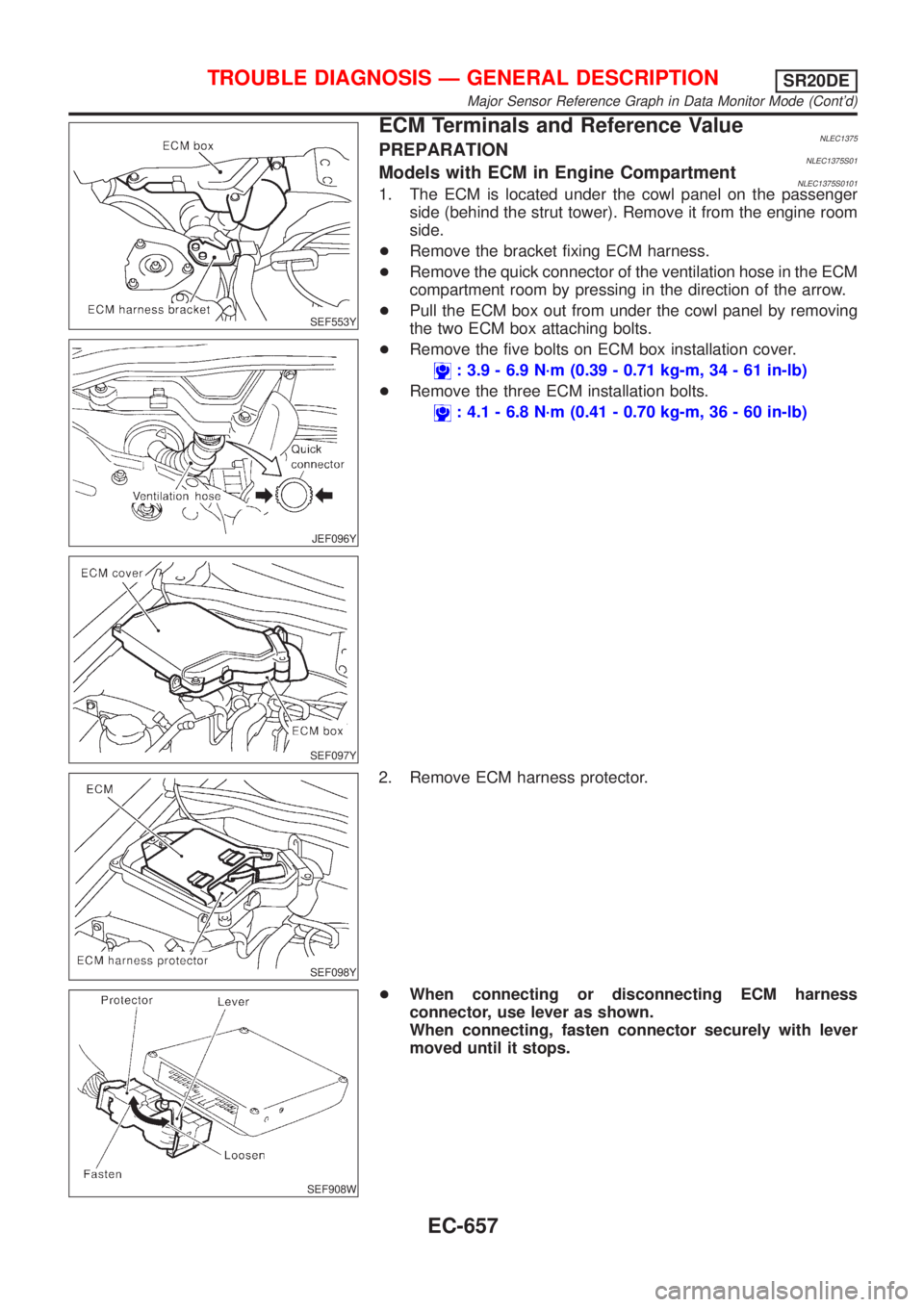
ECM Terminals and Reference ValueNLEC1375PREPARATIONNLEC1375S01Models with ECM in Engine CompartmentNLEC1375S01011. The ECM is located under the cowl panel on the passenger
side (behind the strut tower). Remove it from the engine room
side.
+Remove the bracket fixing ECM harness.
+Remove the quick connector of the ventilation hose in the ECM
compartment room by pressing in the direction of the arrow.
+Pull the ECM box out from under the cowl panel by removing
the two ECM box attaching bolts.
+Remove the five bolts on ECM box installation cover.
: 3.9 - 6.9 N´m (0.39 - 0.71 kg-m, 34 - 61 in-lb)
+Remove the three ECM installation bolts.
: 4.1 - 6.8 N´m (0.41 - 0.70 kg-m, 36 - 60 in-lb)
SEF098Y
2. Remove ECM harness protector.
SEF908W
+When connecting or disconnecting ECM harness
connector, use lever as shown.
When connecting, fasten connector securely with lever
moved until it stops.
TROUBLE DIAGNOSIS Ð GENERAL DESCRIPTIONSR20DE
Major Sensor Reference Graph in Data Monitor Mode (Cont'd)
EC-657
Page 1332 of 3051
8 CHECK RESISTOR
Refer to ªComponent Inspectionº EC-908.
OK or NG
OK©GO TO 9.
NG©Replace distributor cap.
9 CHECK INTERMITTENT INCIDENT
Perform ªTROUBLE DIAGNOSIS FOR INTERMITTENT INCIDENTº, EC-670.
©INSPECTION END
SEF237X
SEF238X
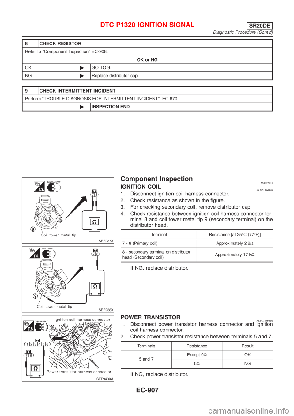
Component InspectionNLEC1916IGNITION COILNLEC1916S011. Disconnect ignition coil harness connector.
2. Check resistance as shown in the figure.
3. For checking secondary coil, remove distributor cap.
4. Check resistance between ignition coil harness connector ter-
minal 8 and coil tower metal tip 9 (secondary terminal) on the
distributor head.
Terminal Resistance [at 25ÉC (77ÉF)]
7 - 8 (Primary coil) Approximately 2.2W
8 - secondary terminal on distributor
head (Secondary coil)Approximately 17 kW
If NG, replace distributor.
SEF943XA
POWER TRANSISTORNLEC1916S021. Disconnect power transistor harness connector and ignition
coil harness connector.
2. Check power transistor resistance between terminals 5 and 7.
Terminals Resistance Result
5 and 7Except 0WOK
0WNG
If NG, replace distributor.
DTC P1320 IGNITION SIGNALSR20DE
Diagnostic Procedure (Cont'd)
EC-907
Page 1435 of 3051
8 CHECK RESISTOR
Refer to ªComponent Inspectionº EC-1011.
OK or NG
OK©GO TO 9.
NG©Replace distributor cap.
9 CHECK INTERMITTENT INCIDENT
Perform ªTROUBLE DIAGNOSIS FOR INTERMITTENT INCIDENTº, EC-670.
©INSPECTION END
SEF237X
SEF238X
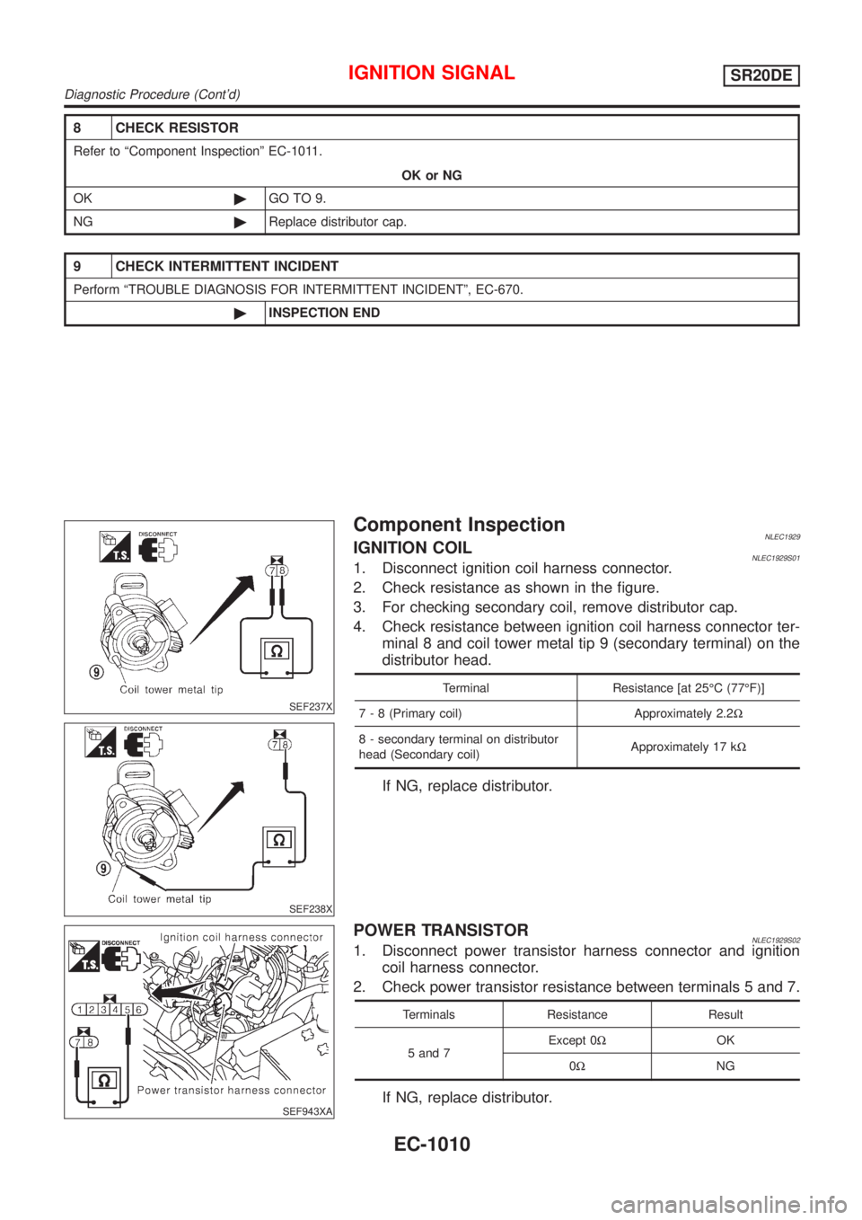
Component InspectionNLEC1929IGNITION COILNLEC1929S011. Disconnect ignition coil harness connector.
2. Check resistance as shown in the figure.
3. For checking secondary coil, remove distributor cap.
4. Check resistance between ignition coil harness connector ter-
minal 8 and coil tower metal tip 9 (secondary terminal) on the
distributor head.
Terminal Resistance [at 25ÉC (77ÉF)]
7 - 8 (Primary coil) Approximately 2.2W
8 - secondary terminal on distributor
head (Secondary coil)Approximately 17 kW
If NG, replace distributor.
SEF943XA
POWER TRANSISTORNLEC1929S021. Disconnect power transistor harness connector and ignition
coil harness connector.
2. Check power transistor resistance between terminals 5 and 7.
Terminals Resistance Result
5 and 7Except 0WOK
0WNG
If NG, replace distributor.
IGNITION SIGNALSR20DE
Diagnostic Procedure (Cont'd)
EC-1010
Page 1515 of 3051
JEF360Y
JEF361Y
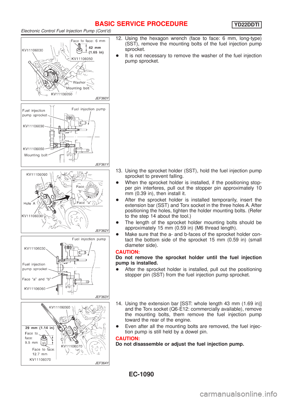
12. Using the hexagon wrench (face to face: 6 mm, long-type)
(SST), remove the mounting bolts of the fuel injection pump
sprocket.
+It is not necessary to remove the washer of the fuel injection
pump sprocket.
JEF362Y
JEF363Y
13. Using the sprocket holder (SST), hold the fuel injection pump
sprocket to prevent falling.
+When the sprocket holder is installed, if the positioning stop-
per pin interferes, pull out the stopper pin approximately 10
mm (0.39 in), then install it.
+After the sprocket holder is installed temporarily, insert the
extension bar (SST) and Torx socket in the three holes A. After
positioning the holes, tighten the holder mounting bolts. (Refer
to the step 14 about the tool.)
+The length of the sprocket holder mounting bolts should be
approximately 15 mm (0.59 in) (M6 thread length).
+Make sure that the a- and b-faces of the sprocket holder con-
tact the bottom side of the sprocket 15 mm (0.59 in) (small
diameter side).
CAUTION:
Do not remove the sprocket holder until the fuel injection
pump is installed.
+After the sprocket holder is installed, pull out the positioning
stopper pin (SST) from the fuel injection pump sprocket.
JEF364Y
14. Using the extension bar [SST: whole length 43 mm (1.69 in)]
and the Torx socket (Q6-E12: commercially available), remove
the mounting bolts, them remove the fuel injection pump
toward the rear of the engine.
+Even after all the mounting bolts are removed, the fuel injec-
tion pump is still held by a dowel pin.
CAUTION:
Do not disassemble or adjust the fuel injection pump.
BASIC SERVICE PROCEDUREYD22DDTI
Electronic Control Fuel Injection Pump (Cont'd)
EC-1090
Page 1554 of 3051
SEF396Y
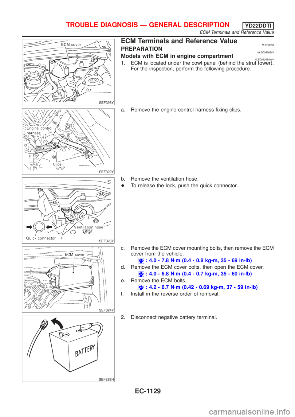
ECM Terminals and Reference ValueNLEC0636PREPARATIONNLEC0636S01Models with ECM in engine compartmentNLEC0636S01011. ECM is located under the cowl panel (behind the strut tower).
For the inspection, perform the following procedure.
SEF322Y
a. Remove the engine control harness fixing clips.
SEF323Y
b. Remove the ventilation hose.
+To release the lock, push the quick connector.
SEF324Y
c. Remove the ECM cover mounting bolts, then remove the ECM
cover from the vehicle.
: 4.0 - 7.8 N´m (0.4 - 0.8 kg-m, 35 - 69 in-lb)
d. Remove the ECM cover bolts, then open the ECM cover.
: 4.0 - 6.8 N´m (0.4 - 0.7 kg-m, 35 - 60 in-lb)
e. Remove the ECM bolts.
: 4.2 - 6.7 N´m (0.42 - 0.69 kg-m, 37 - 59 in-lb)
f. Install in the reverse order of removal.
SEF289H
2. Disconnect negative battery terminal.
TROUBLE DIAGNOSIS Ð GENERAL DESCRIPTIONYD22DDTI
ECM Terminals and Reference Value
EC-1129
Page 1896 of 3051
Component Parts and Harness Connector
Location
NLEL0452For details, refer to ªELECTRICAL UNIT LOCATIONº (EL-442) and ªHARNESS LAYOUTº (EL-452).
System DescriptionNLEL0453The warning chime is controlled by the time control unit.
The warning chime is located in the time control unit.
Power is supplied at all times
+through 15A fuse [No. 5, located in fuse block (J/B)]
+to time control unit terminal 9.
+through 10A fuse [No. 12, located in the fuse block (J/B)]
+to key switch terminal 1.
+through 10A fuse (No. 38, located in the fuse and fusible link box)
+to lighting switch terminal 11.
With the ignition switch in the ON or START position, power is supplied
+through 10A fuse [No. 10, located in the fuse block (J/B)]
+to time control unit terminal 1.
Ground is supplied to time control unit terminal 16 through body grounds M28 and M48.
When a signal, or combination of signals, is received by the time control unit, the warning chime will sound.
IGNITION KEY WARNING CHIMENLEL0453S01With the key in the ignition switch in the OFF position, the driver's door open and driver's door locked, the
warning chime will sound. Power is supplied
+from key switch terminal 2
+to time control unit terminal 22.
Ground is supplied
+from body grounds B24 and B30
+through front door switch (driver side) terminals 3 and 2
+to time control unit terminal 6, and
Ground is interrupted,
+from body grounds M28 and M48
+to time control unit terminal 35
LIGHT WARNING CHIMENLEL0453S02With ignition switch OFF, driver's door open, and lighting switch in 1ST or 2ND position, warning chime will
sound. Power is supplied.
+from lighting switch terminal 12
+to time control unit terminal 10
Ground is supplied
+from front door switch (driver side) terminal 2
+to time control unit terminal 6.
Front door switch (driver side) terminal 3 is grounded through body grounds B24 and B30.
TRAILER DIRECTION INDICATOR WARNING CHIMENLEL0453S04This warning chime will be sounded while the direction indicator (turn signal lamp) is in operation with towing
the trailer.
This is an audible feedback (warning chime) to the driver.
If no audible feedback is heard while towing the trailer and operating the turn signal, this indicates the bulb
failure of the trailer.
Time control unit will detect the additional electrical load of a turn signal lamp for trailer automatically. Then
the chime will be sounded by the time control unit internally with the operation of the turn signal.
WARNING CHIME
Component Parts and Harness Connector Location
EL-165