2001 NISSAN ALMERA TINO tow
[x] Cancel search: towPage 2057 of 3051
Description=NLEL0485The TCU has the following functions.
INTERIOR LAMP TIMERNLEL0485S01The interior lamp timer is controlled by the TCU.
For further information, refer to ªINTERIOR ROOM LAMPº (EL-116).
IGNITION KEY WARNING CHIME, LIGHT WARNING CHIME AND TRAILER DIRECTION
INDICATOR WARNING CHIME
NLEL0485S02The ignition key and light warning chime are controlled by the TCU.
For further information, refer to ªWARNING CHIMEº (EL-165).
REAR WINDOW DEFOGGER TIMERNLEL0485S03The rear window defogger and door mirror defogger system are controlled by the TCU.
For further information, refer to ªREAR WINDOW DEFOGGERº (EL-198).
POWER DOOR LOCK (SUPER LOCK)NLEL0485S04The power door lock (super lock) is controlled by the TCU.
For further information, refer to ªPOWER DOOR LOCK Ð Super Lock к (EL-281).
MULTI-REMOTE CONTROL SYSTEMNLEL0485S05The multi-remote control system is controlled by the TCU.
For further information, refer to ªMULTI-REMOTE CONTROL SYSTEMº (EL-314).
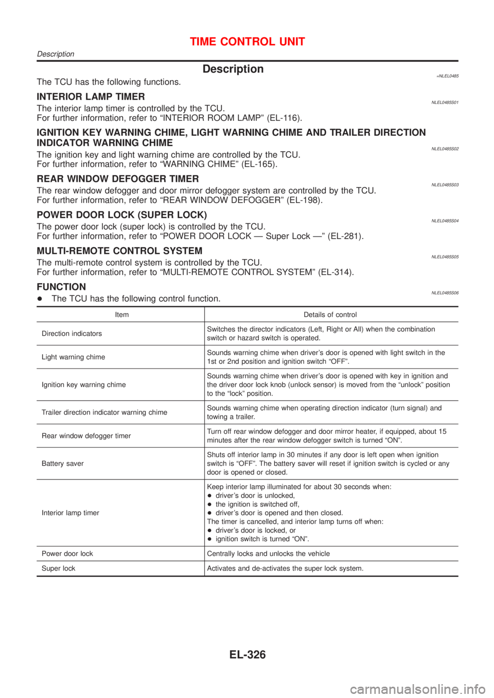
FUNCTIONNLEL0485S06+The TCU has the following control function.
Item Details of control
Direction indicatorsSwitches the director indicators (Left, Right or All) when the combination
switch or hazard switch is operated.
Light warning chimeSounds warning chime when driver's door is opened with light switch in the
1st or 2nd position and ignition switch ªOFFº.
Ignition key warning chimeSounds warning chime when driver's door is opened with key in ignition and
the driver door lock knob (unlock sensor) is moved from the ªunlockº position
to the ªlockº position.
Trailer direction indicator warning chimeSounds warning chime when operating direction indicator (turn signal) and
towing a trailer.
Rear window defogger timerTurn off rear window defogger and door mirror heater, if equipped, about 15
minutes after the rear window defogger switch is turned ªONº.
Battery saverShuts off interior lamp in 30 minutes if any door is left open when ignition
switch is ªOFFº. The battery saver will reset if ignition switch is cycled or any
door is opened or closed.
Interior lamp timerKeep interior lamp illuminated for about 30 seconds when:
+driver's door is unlocked,
+the ignition is switched off,
+driver's door is opened and then closed.
The timer is cancelled, and interior lamp turns off when:
+driver's door is locked, or
+ignition switch is turned ªONº.
Power door lock Centrally locks and unlocks the vehicle
Super lock Activates and de-activates the super lock system.
TIME CONTROL UNIT
Description
EL-326
Page 2168 of 3051
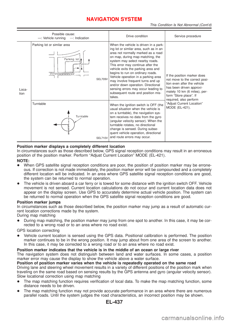
Possible cause:
Ð: Vehicle running ---: IndicationDrive condition Service procedure
Loca-
tionParking lot or similar area
SEL709V
When the vehicle is driven in a park-
ing lot or similar area, such as in an
area not normally marked as a road
on map, during map matching, the
system may select nearby roads.
This error may continue after the
vehicle exits the parking area and
begins to run on ordinary roads.
Vehicle operation in a parking area
may involve frequent turns and up
and/or down operation. Directional
sensing errors may occur leading to
subsequent route and position mis-
takes.If the position marker does
not move to the correct posi-
tion even after the vehicle
has been driven approxi-
mately 10 km (6 miles), per-
form ªStore placeº. If
required, also perform
ªAdjust Current Locationº
MODE (EL-421). Turntable
SEL710V
When the ignition switch is OFF (the
usual situation when the vehicle is
on a turntable), the navigation sys-
tem receives no data from the gyro
(angular velocity sensor). When the
turntable rotates, no directional
change is sensed. During subse-
quent vehicle operation, directional
and route errors may occur.
Position marker displays a completely different location
In circumstances such as those described below, GPS signal reception conditions may result in an erroneous
position of the position marker. Perform ªAdjust Current Locationº MODE (EL-421).
NOTE:
+When GPS satellite signal reception conditions are poor, the position of position marker may be errone-
ous. If correction is not made immediately, the position marker error will be compounded and a completely
different location will be indicated. In an area where GPS satellite signal reception conditions are good,
the system can be returned to normal operation.
+The vehicle is driven aboard a car ferry or is towed for some distance with the ignition switch OFF. Vehicle
movement is not sensed. Current location calculations do not occur and current location data does not
appear on the display screen. Use GPS to accurately determine actual vehicle position. The system can
be returned to normal operation when the GPS satellite signal reception conditions are good.
Position marker jumps
In circumstances such as those described below, the position marker may jump as a result of automatic cur-
rent location corrections made by the system.
During map matching
+During map matching, the position marker may jump from one spot to another. In this case, it may be cor-
rected to a wrong road or to an area where no road exist.
GPS location correcting
+Vehicle current location is sensed using the GPS data. Positional calibration is performed. The position
marker continues to be in the wrong position. It may jump about from one area of the screen to another.
In this case, it may be corrected to a wrong road or to an area where no road exist.
Position marker indicates that the vehicle is in the middle of an ocean or large river
The navigation system does not distinguish between land and water surfaces. In some cases, a position
marker error may cause the display to show the vehicle above a water surface.
Position of position marker varies when the vehicle is repeatedly operated on the same road
Driving lane and steering wheel movement results in a variety of different positions of the position mark when
traveling on the same road based on sensing results by the GPS antenna and gyro (angular velocity sensor).
Slow locational correction using map matching
+The map matching function requires verification of local data. To make the map matching function, some
distance needs to be driven.
+The map matching function may not provide accurate performance in an area where there are numerous
parallel roads. Until the system judges the road characteristics, an incorrect position may be shown.
NAVIGATION SYSTEM
This Condition Is Not Abnormal (Cont'd)
EL-437
Page 2300 of 3051
SEM139D
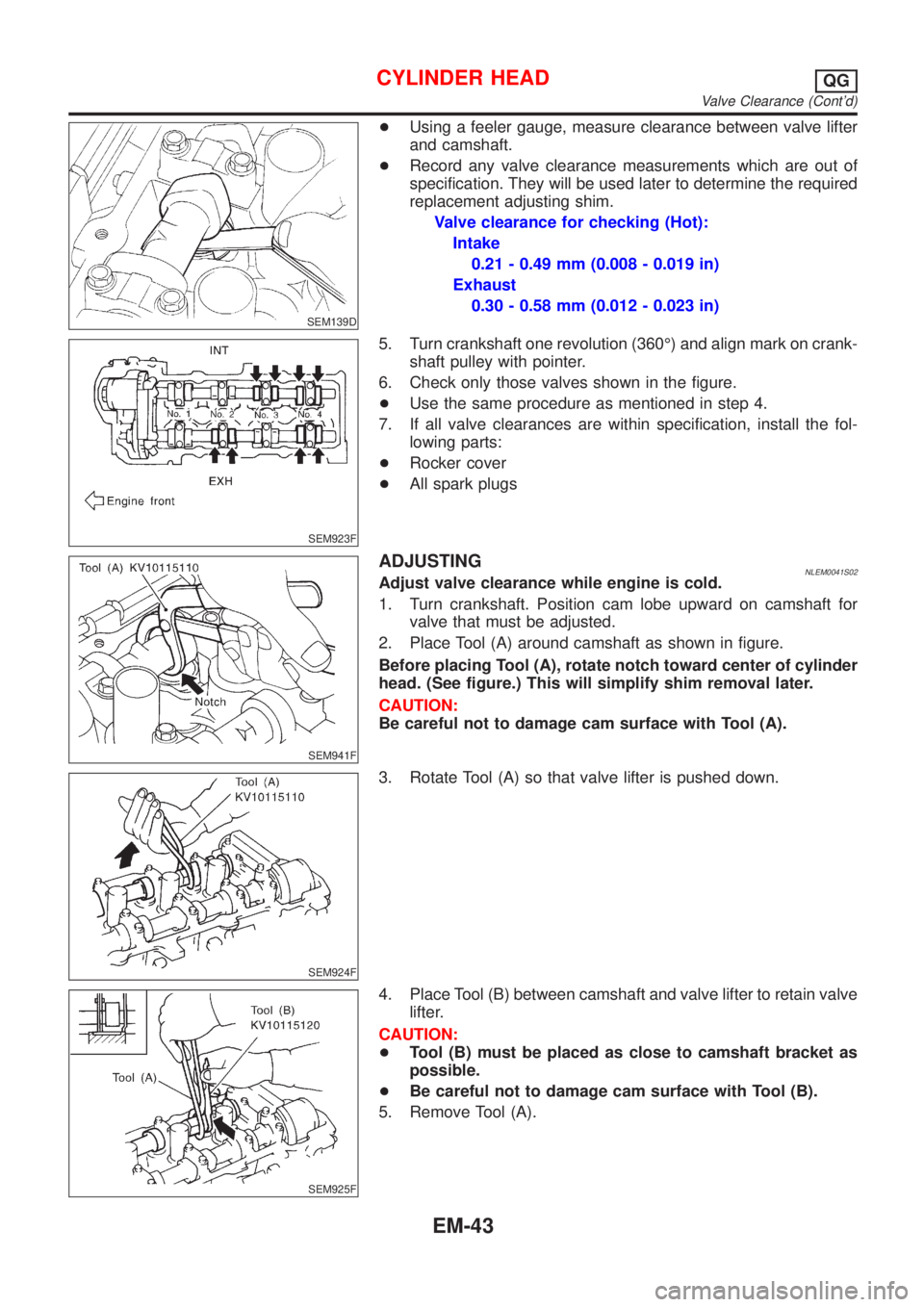
+Using a feeler gauge, measure clearance between valve lifter
and camshaft.
+Record any valve clearance measurements which are out of
specification. They will be used later to determine the required
replacement adjusting shim.
Valve clearance for checking (Hot):
Intake
0.21 - 0.49 mm (0.008 - 0.019 in)
Exhaust
0.30 - 0.58 mm (0.012 - 0.023 in)
SEM923F
5. Turn crankshaft one revolution (360É) and align mark on crank-
shaft pulley with pointer.
6. Check only those valves shown in the figure.
+Use the same procedure as mentioned in step 4.
7. If all valve clearances are within specification, install the fol-
lowing parts:
+Rocker cover
+All spark plugs
SEM941F
ADJUSTINGNLEM0041S02Adjust valve clearance while engine is cold.
1. Turn crankshaft. Position cam lobe upward on camshaft for
valve that must be adjusted.
2. Place Tool (A) around camshaft as shown in figure.
Before placing Tool (A), rotate notch toward center of cylinder
head. (See figure.) This will simplify shim removal later.
CAUTION:
Be careful not to damage cam surface with Tool (A).
SEM924F
3. Rotate Tool (A) so that valve lifter is pushed down.
SEM925F
4. Place Tool (B) between camshaft and valve lifter to retain valve
lifter.
CAUTION:
+Tool (B) must be placed as close to camshaft bracket as
possible.
+Be careful not to damage cam surface with Tool (B).
5. Remove Tool (A).
CYLINDER HEADQG
Valve Clearance (Cont'd)
EM-43
Page 2302 of 3051
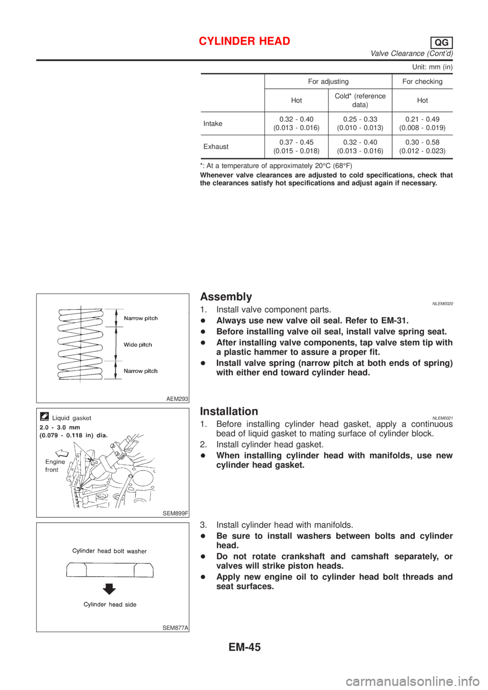
Unit: mm (in)
For adjusting For checking
HotCold* (reference
data)Hot
Intake0.32 - 0.40
(0.013 - 0.016)0.25 - 0.33
(0.010 - 0.013)0.21 - 0.49
(0.008 - 0.019)
Exhaust0.37 - 0.45
(0.015 - 0.018)0.32 - 0.40
(0.013 - 0.016)0.30 - 0.58
(0.012 - 0.023)
*: At a temperature of approximately 20ÉC (68ÉF)
Whenever valve clearances are adjusted to cold specifications, check that
the clearances satisfy hot specifications and adjust again if necessary.
AEM293
AssemblyNLEM00201. Install valve component parts.
+Always use new valve oil seal. Refer to EM-31.
+Before installing valve oil seal, install valve spring seat.
+After installing valve components, tap valve stem tip with
a plastic hammer to assure a proper fit.
+Install valve spring (narrow pitch at both ends of spring)
with either end toward cylinder head.
SEM899F
InstallationNLEM00211. Before installing cylinder head gasket, apply a continuous
bead of liquid gasket to mating surface of cylinder block.
2. Install cylinder head gasket.
+When installing cylinder head with manifolds, use new
cylinder head gasket.
SEM877A
3. Install cylinder head with manifolds.
+Be sure to install washers between bolts and cylinder
head.
+Do not rotate crankshaft and camshaft separately, or
valves will strike piston heads.
+Apply new engine oil to cylinder head bolt threads and
seat surfaces.
CYLINDER HEADQG
Valve Clearance (Cont'd)
EM-45
Page 2359 of 3051
SEM990C
SEM991C
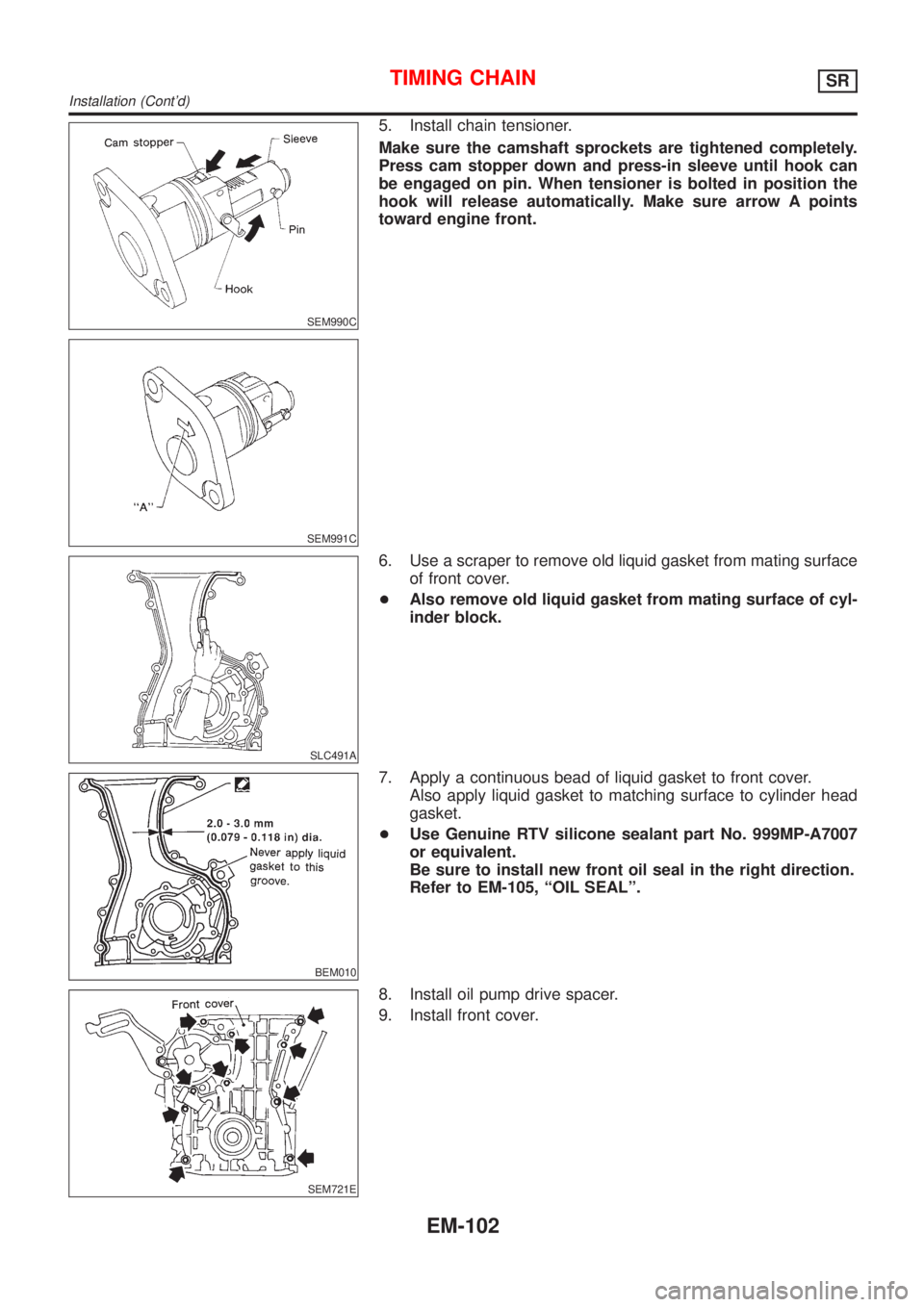
5. Install chain tensioner.
Make sure the camshaft sprockets are tightened completely.
Press cam stopper down and press-in sleeve until hook can
be engaged on pin. When tensioner is bolted in position the
hook will release automatically. Make sure arrow A points
toward engine front.
SLC491A
6. Use a scraper to remove old liquid gasket from mating surface
of front cover.
+Also remove old liquid gasket from mating surface of cyl-
inder block.
BEM010
7. Apply a continuous bead of liquid gasket to front cover.
Also apply liquid gasket to matching surface to cylinder head
gasket.
+Use Genuine RTV silicone sealant part No. 999MP-A7007
or equivalent.
Be sure to install new front oil seal in the right direction.
Refer to EM-105, ªOIL SEALº.
SEM721E
8. Install oil pump drive spacer.
9. Install front cover.
TIMING CHAINSR
Installation (Cont'd)
EM-102
Page 2378 of 3051
SEM085D
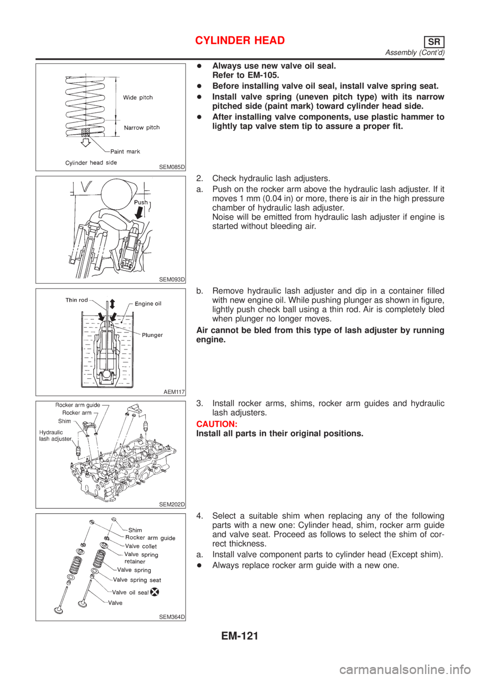
+Always use new valve oil seal.
Refer to EM-105.
+Before installing valve oil seal, install valve spring seat.
+Install valve spring (uneven pitch type) with its narrow
pitched side (paint mark) toward cylinder head side.
+After installing valve components, use plastic hammer to
lightly tap valve stem tip to assure a proper fit.
SEM093D
2. Check hydraulic lash adjusters.
a. Push on the rocker arm above the hydraulic lash adjuster. If it
moves 1 mm (0.04 in) or more, there is air in the high pressure
chamber of hydraulic lash adjuster.
Noise will be emitted from hydraulic lash adjuster if engine is
started without bleeding air.
AEM117
b. Remove hydraulic lash adjuster and dip in a container filled
with new engine oil. While pushing plunger as shown in figure,
lightly push check ball using a thin rod. Air is completely bled
when plunger no longer moves.
Air cannot be bled from this type of lash adjuster by running
engine.
SEM202D
3. Install rocker arms, shims, rocker arm guides and hydraulic
lash adjusters.
CAUTION:
Install all parts in their original positions.
SEM364D
4. Select a suitable shim when replacing any of the following
parts with a new one: Cylinder head, shim, rocker arm guide
and valve seat. Proceed as follows to select the shim of cor-
rect thickness.
a. Install valve component parts to cylinder head (Except shim).
+Always replace rocker arm guide with a new one.
CYLINDER HEADSR
Assembly (Cont'd)
EM-121
Page 2379 of 3051
SEM365DA
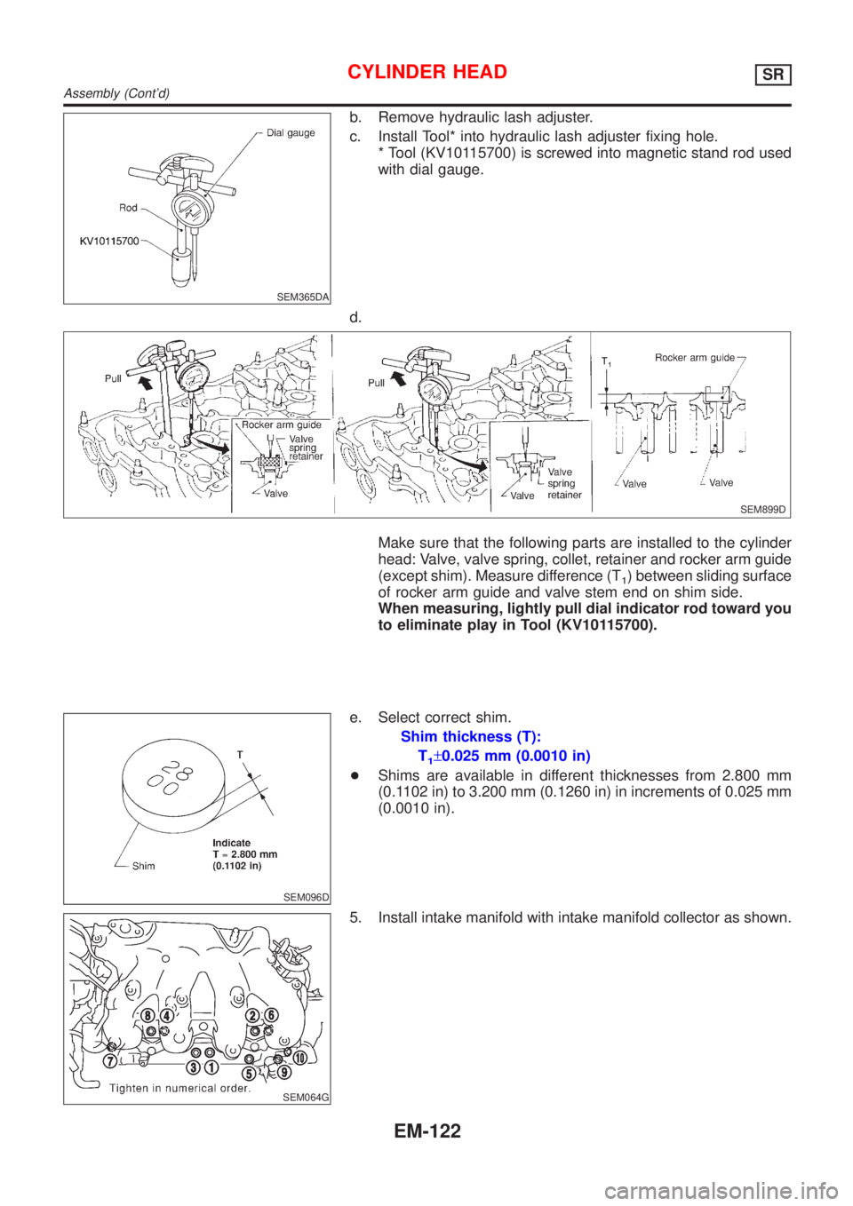
b. Remove hydraulic lash adjuster.
c. Install Tool* into hydraulic lash adjuster fixing hole.
* Tool (KV10115700) is screwed into magnetic stand rod used
with dial gauge.
d.
SEM899D
Make sure that the following parts are installed to the cylinder
head: Valve, valve spring, collet, retainer and rocker arm guide
(except shim). Measure difference (T
1) between sliding surface
of rocker arm guide and valve stem end on shim side.
When measuring, lightly pull dial indicator rod toward you
to eliminate play in Tool (KV10115700).
SEM096D
e. Select correct shim.
Shim thickness (T):
T
1±0.025 mm (0.0010 in)
+Shims are available in different thicknesses from 2.800 mm
(0.1102 in) to 3.200 mm (0.1260 in) in increments of 0.025 mm
(0.0010 in).
SEM064G
5. Install intake manifold with intake manifold collector as shown.
CYLINDER HEADSR
Assembly (Cont'd)
EM-122
Page 2384 of 3051
SEM049G
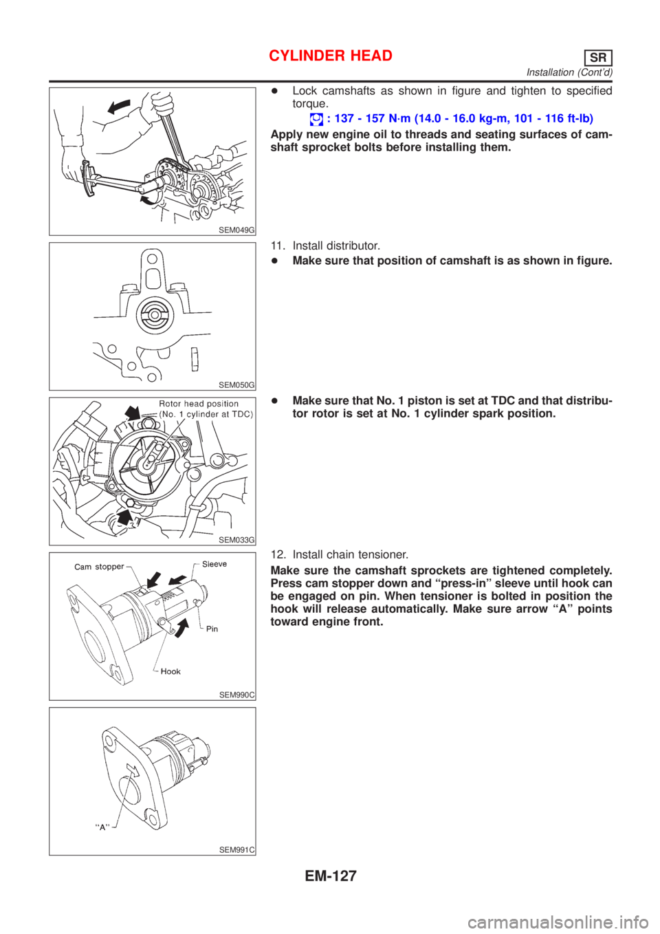
+Lock camshafts as shown in figure and tighten to specified
torque.
: 137 - 157 N´m (14.0 - 16.0 kg-m, 101 - 116 ft-lb)
Apply new engine oil to threads and seating surfaces of cam-
shaft sprocket bolts before installing them.
SEM050G
11. Install distributor.
+Make sure that position of camshaft is as shown in figure.
SEM033G
+Make sure that No. 1 piston is set at TDC and that distribu-
tor rotor is set at No. 1 cylinder spark position.
SEM990C
SEM991C
12. Install chain tensioner.
Make sure the camshaft sprockets are tightened completely.
Press cam stopper down and ªpress-inº sleeve until hook can
be engaged on pin. When tensioner is bolted in position the
hook will release automatically. Make sure arrow ªAº points
toward engine front.
CYLINDER HEADSR
Installation (Cont'd)
EM-127