2001 NISSAN ALMERA height
[x] Cancel search: heightPage 2280 of 2898
If out of specification, replace piston ring. If gap still exceeds the
limit even with a new ring, do the following. Rebore cylinder and
use oversized piston and piston rings.
Refer to SDS (EM-167).
+When replacing the piston, check the cylinder block surface for
scratches or seizure. If scratches or seizure is found, hone or
replace the cylinder block.
SEM038F
SEM003F
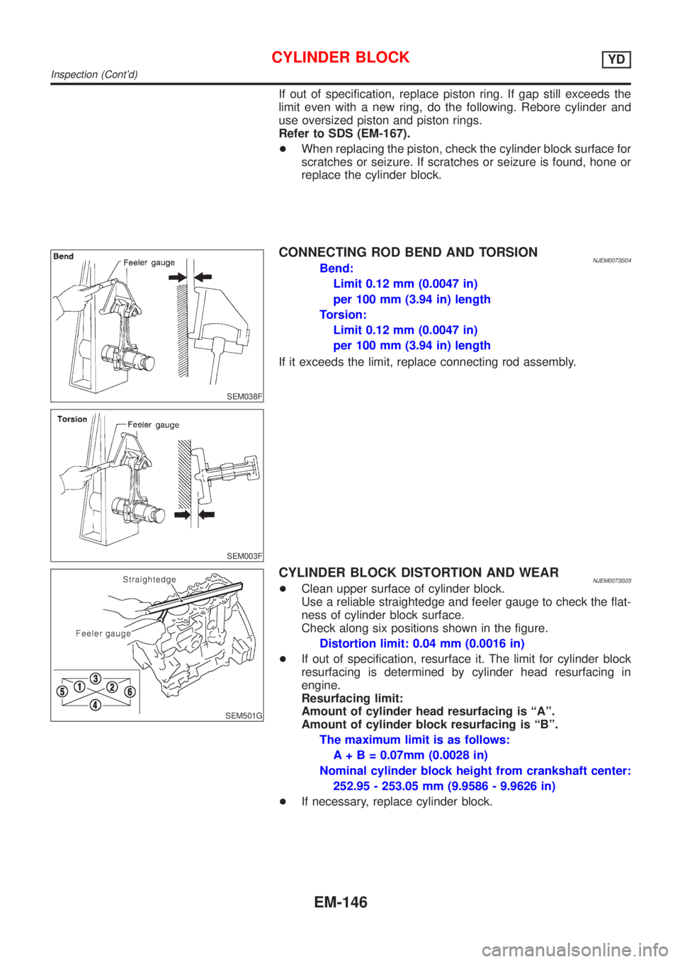
CONNECTING ROD BEND AND TORSIONNJEM0073S04Bend:
Limit 0.12 mm (0.0047 in)
per 100 mm (3.94 in) length
Torsion:
Limit 0.12 mm (0.0047 in)
per 100 mm (3.94 in) length
If it exceeds the limit, replace connecting rod assembly.
SEM501G
CYLINDER BLOCK DISTORTION AND WEARNJEM0073S05+Clean upper surface of cylinder block.
Use a reliable straightedge and feeler gauge to check the flat-
ness of cylinder block surface.
Check along six positions shown in the figure.
Distortion limit: 0.04 mm (0.0016 in)
+If out of specification, resurface it. The limit for cylinder block
resurfacing is determined by cylinder head resurfacing in
engine.
Resurfacing limit:
Amount of cylinder head resurfacing is ªAº.
Amount of cylinder block resurfacing is ªBº.
The maximum limit is as follows:
A + B = 0.07mm (0.0028 in)
Nominal cylinder block height from crankshaft center:
252.95 - 253.05 mm (9.9586 - 9.9626 in)
+If necessary, replace cylinder block.
CYLINDER BLOCKYD
Inspection (Cont'd)
EM-146
Page 2287 of 2898
EM142
Method B (Using plastigage)
CAUTION:
+Do not turn crankshaft or connecting rod while plastigage
is being inserted.
+When bearing clearance exceeds the specified limit,
ensure that the proper bearing has been installed. If incor-
rect bearing clearance exists, use a thicker or undersized
main bearing to ensure specified clearance.
SEM502G
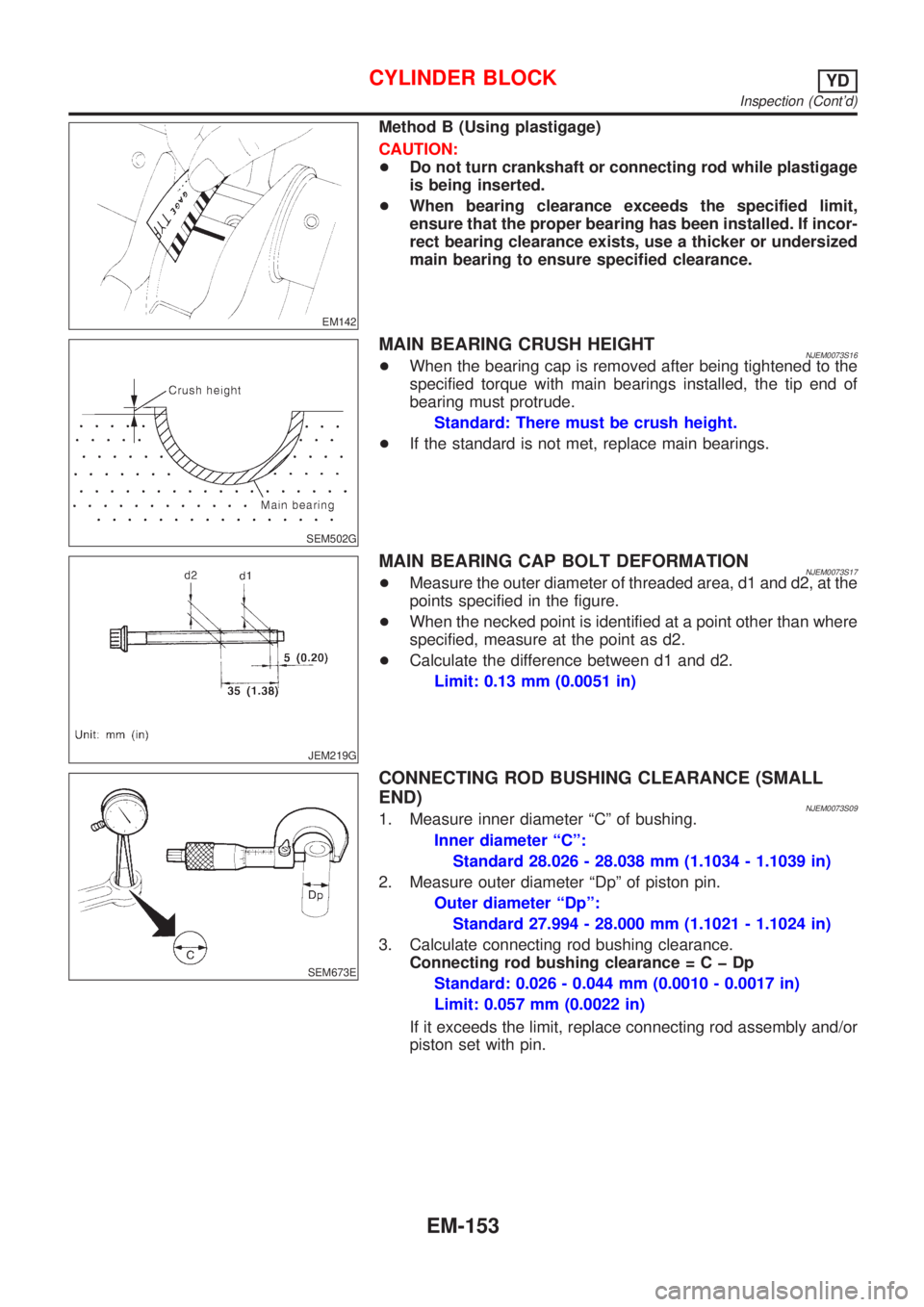
MAIN BEARING CRUSH HEIGHTNJEM0073S16+When the bearing cap is removed after being tightened to the
specified torque with main bearings installed, the tip end of
bearing must protrude.
Standard: There must be crush height.
+If the standard is not met, replace main bearings.
JEM219G
MAIN BEARING CAP BOLT DEFORMATIONNJEM0073S17+Measure the outer diameter of threaded area, d1 and d2, at the
points specified in the figure.
+When the necked point is identified at a point other than where
specified, measure at the point as d2.
+Calculate the difference between d1 and d2.
Limit: 0.13 mm (0.0051 in)
SEM673E
CONNECTING ROD BUSHING CLEARANCE (SMALL
END)
NJEM0073S091. Measure inner diameter ªCº of bushing.
Inner diameter ªCº:
Standard 28.026 - 28.038 mm (1.1034 - 1.1039 in)
2. Measure outer diameter ªDpº of piston pin.
Outer diameter ªDpº:
Standard 27.994 - 28.000 mm (1.1021 - 1.1024 in)
3. Calculate connecting rod bushing clearance.
Connecting rod bushing clearance=CþDp
Standard: 0.026 - 0.044 mm (0.0010 - 0.0017 in)
Limit: 0.057 mm (0.0022 in)
If it exceeds the limit, replace connecting rod assembly and/or
piston set with pin.
CYLINDER BLOCKYD
Inspection (Cont'd)
EM-153
Page 2296 of 2898
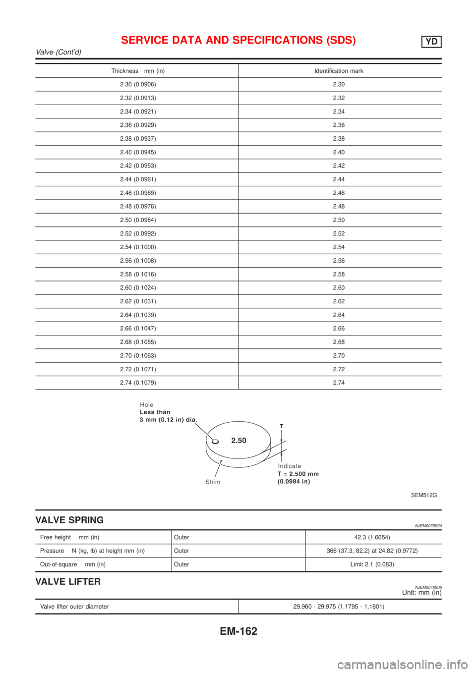
Thickness mm (in) Identification mark
2.30 (0.0906) 2.30
2.32 (0.0913) 2.32
2.34 (0.0921) 2.34
2.36 (0.0929) 2.36
2.38 (0.0937) 2.38
2.40 (0.0945) 2.40
2.42 (0.0953) 2.42
2.44 (0.0961) 2.44
2.46 (0.0969) 2.46
2.48 (0.0976) 2.48
2.50 (0.0984) 2.50
2.52 (0.0992) 2.52
2.54 (0.1000) 2.54
2.56 (0.1008) 2.56
2.58 (0.1016) 2.58
2.60 (0.1024) 2.60
2.62 (0.1031) 2.62
2.64 (0.1039) 2.64
2.66 (0.1047) 2.66
2.68 (0.1055) 2.68
2.70 (0.1063) 2.70
2.72 (0.1071) 2.72
2.74 (0.1079) 2.74
SEM512G
VALVE SPRINGNJEM0078S04
Free height mm (in) Outer 42.3 (1.6654)
Pressure N (kg, lb) at height mm (in) Outer 366 (37.3, 82.2) at 24.82 (0.9772)
Out-of-square mm (in) Outer Limit 2.1 (0.083)
VALVE LIFTERNJEM0078S05Unit: mm (in)
Valve lifter outer diameter 29.960 - 29.975 (1.1795 - 1.1801)
SERVICE DATA AND SPECIFICATIONS (SDS)YD
Valve (Cont'd)
EM-162
Page 2299 of 2898
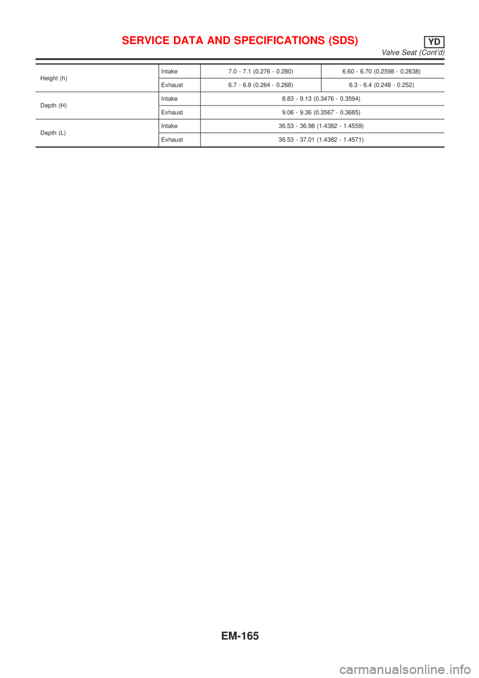
Height (h)Intake 7.0 - 7.1 (0.276 - 0.280) 6.60 - 6.70 (0.2598 - 0.2638)
Exhaust 6.7 - 6.8 (0.264 - 0.268) 6.3 - 6.4 (0.248 - 0.252)
Depth (H)Intake 8.83 - 9.13 (0.3476 - 0.3594)
Exhaust 9.06 - 9.36 (0.3567 - 0.3685)
Depth (L)Intake 36.53 - 36.98 (1.4382 - 1.4559)
Exhaust 36.53 - 37.01 (1.4382 - 1.4571)
SERVICE DATA AND SPECIFICATIONS (SDS)YD
Valve Seat (Cont'd)
EM-165
Page 2300 of 2898
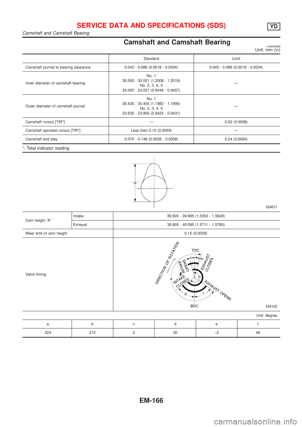
Camshaft and Camshaft Bearing=NJEM0080Unit: mm (in)
Standard Limit
Camshaft journal to bearing clearance 0.045 - 0.086 (0.0018 - 0.0034) 0.045 - 0.086 (0.0018 - 0.0034)
Inner diameter of camshaft bearingNo. 1
30.500 - 30.521 (1.2008 - 1.2016)
No. 2, 3, 4, 5
24.000 - 24.021 (0.9449 - 0.9457)Ð
Outer diameter of camshaft journalNo. 1
30.435 - 30.455 (1.1982 - 1.1990)
No. 2, 3, 4, 5
23.935 - 23.955 (0.9423 - 0.9431)Ð
Camshaft runout [TIR*] Ð 0.02 (0.0008)
Camshaft sprocket runout [TIR*] Less than 0.15 (0.0059) Ð
Camshaft end play 0.070 - 0.148 (0.0028 - 0.0058) 0.24 (0.0094)
*: Total indicator reading
EM671
Cam height ªAºIntake 39.505 - 39.695 (1.5553 - 1.5628)
Exhaust 39.905 - 40.095 (1.5711 - 1.5785)
Wear limit of cam height 0.15 (0.0059)
Valve timing
EM120
Unit: degree
a bcde f
224 212 2 30 ±2 46
SERVICE DATA AND SPECIFICATIONS (SDS)YD
Camshaft and Camshaft Bearing
EM-166
Page 2319 of 2898
SMA211A
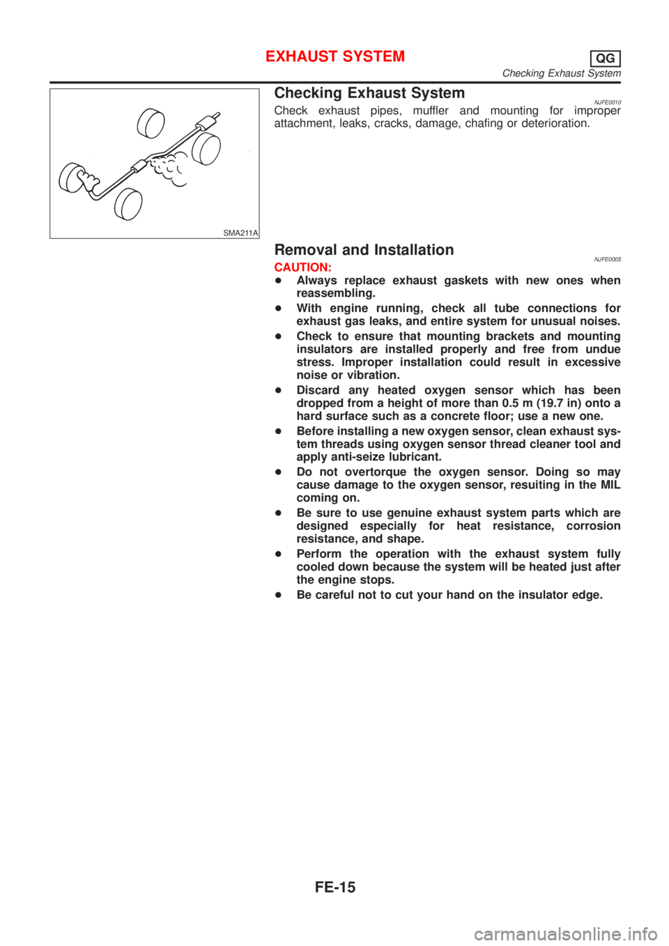
Checking Exhaust SystemNJFE0010Check exhaust pipes, muffler and mounting for improper
attachment, leaks, cracks, damage, chafing or deterioration.
Removal and InstallationNJFE0005CAUTION:
+Always replace exhaust gaskets with new ones when
reassembling.
+With engine running, check all tube connections for
exhaust gas leaks, and entire system for unusual noises.
+Check to ensure that mounting brackets and mounting
insulators are installed properly and free from undue
stress. Improper installation could result in excessive
noise or vibration.
+Discard any heated oxygen sensor which has been
dropped from a height of more than 0.5 m (19.7 in) onto a
hard surface such as a concrete floor; use a new one.
+Before installing a new oxygen sensor, clean exhaust sys-
tem threads using oxygen sensor thread cleaner tool and
apply anti-seize lubricant.
+Do not overtorque the oxygen sensor. Doing so may
cause damage to the oxygen sensor, resuiting in the MIL
coming on.
+Be sure to use genuine exhaust system parts which are
designed especially for heat resistance, corrosion
resistance, and shape.
+Perform the operation with the exhaust system fully
cooled down because the system will be heated just after
the engine stops.
+Be careful not to cut your hand on the insulator edge.
EXHAUST SYSTEMQG
Checking Exhaust System
FE-15
Page 2389 of 2898
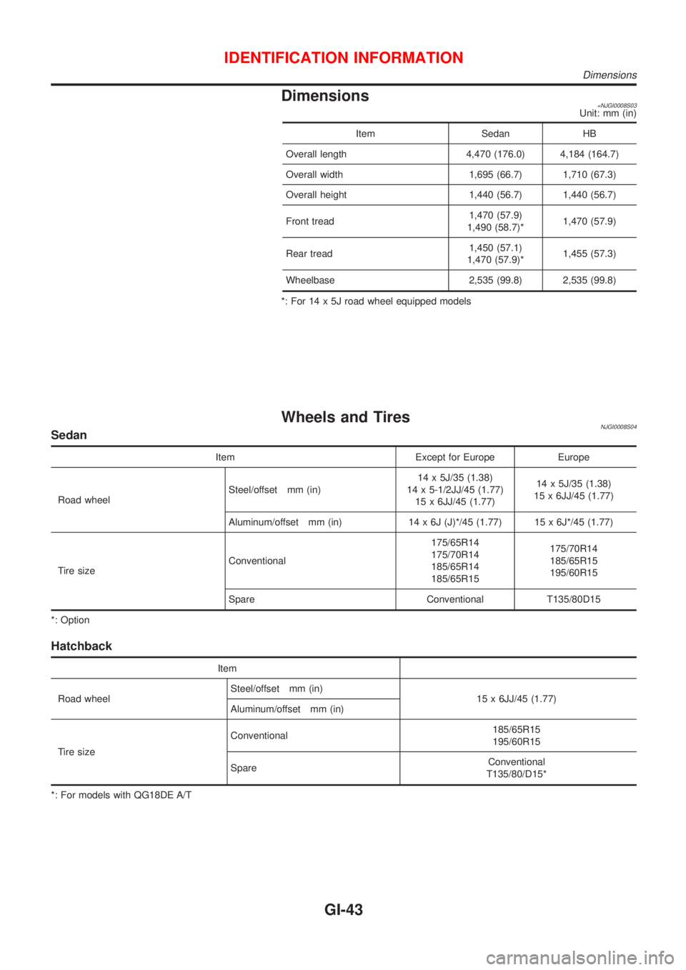
Dimensions=NJGI0008S03Unit: mm (in)
Item Sedan HB
Overall length 4,470 (176.0) 4,184 (164.7)
Overall width 1,695 (66.7) 1,710 (67.3)
Overall height 1,440 (56.7) 1,440 (56.7)
Front tread1,470 (57.9)
1,490 (58.7)*1,470 (57.9)
Rear tread1,450 (57.1)
1,470 (57.9)*1,455 (57.3)
Wheelbase 2,535 (99.8) 2,535 (99.8)
*: For 14 x 5J road wheel equipped models
Wheels and TiresNJGI0008S04Sedan
Item Except for Europe Europe
Road wheelSteel/offset mm (in)14 x 5J/35 (1.38)
14 x 5-1/2JJ/45 (1.77)
15 x 6JJ/45 (1.77)14 x 5J/35 (1.38)
15 x 6JJ/45 (1.77)
Aluminum/offset mm (in) 14 x 6J (J)*/45 (1.77) 15 x 6J*/45 (1.77)
Tire sizeConventional175/65R14
175/70R14
185/65R14
185/65R15175/70R14
185/65R15
195/60R15
Spare Conventional T135/80D15
*: Option
Hatchback
Item
Road wheelSteel/offset mm (in)
15 x 6JJ/45 (1.77)
Aluminum/offset mm (in)
Tire sizeConventional185/65R15
195/60R15
SpareConventional
T135/80/D15*
*: For models with QG18DE A/T
IDENTIFICATION INFORMATION
Dimensions
GI-43
Page 2503 of 2898
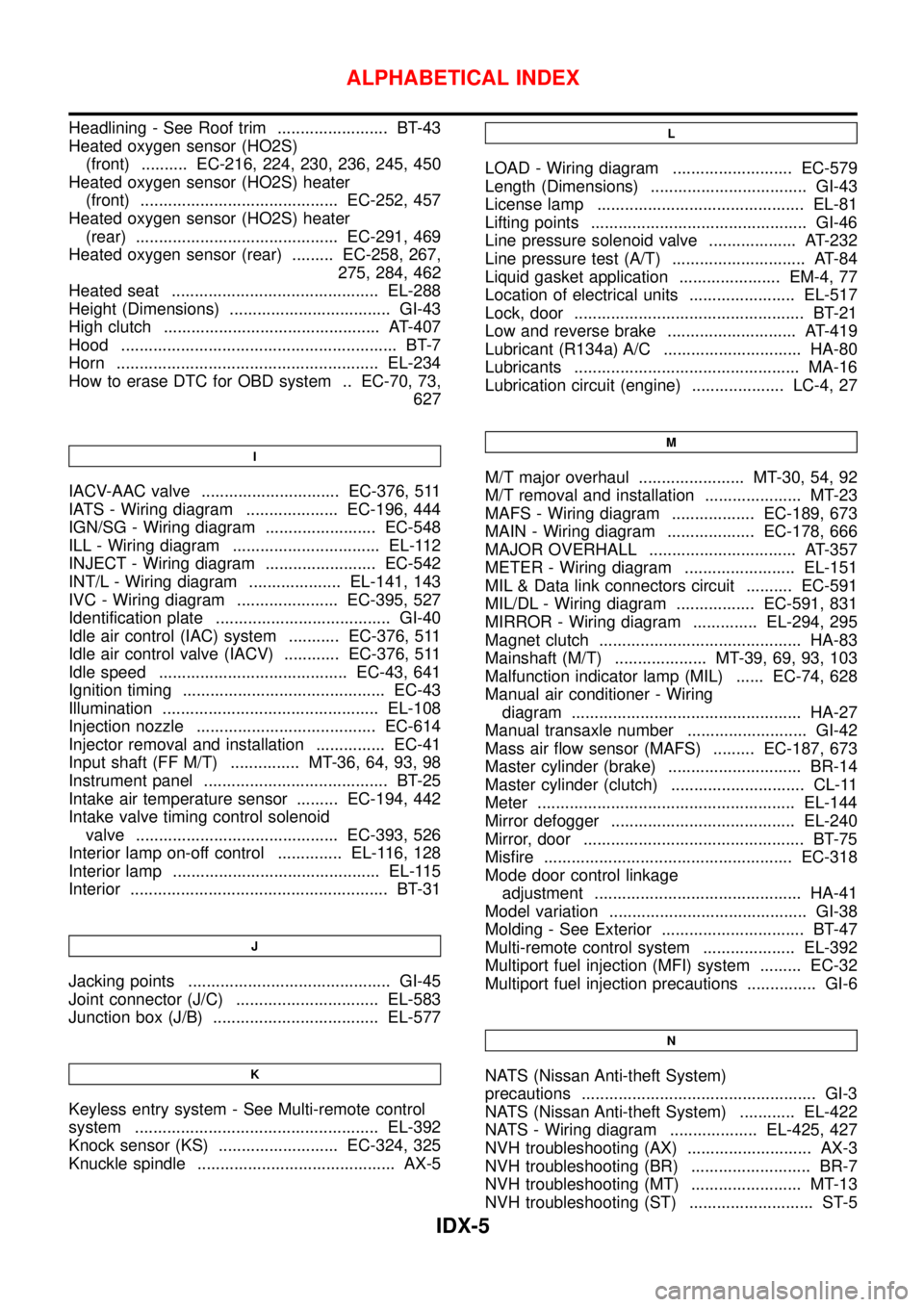
Headlining - See Roof trim ........................ BT-43
Heated oxygen sensor (HO2S)
(front) .......... EC-216, 224, 230, 236, 245, 450
Heated oxygen sensor (HO2S) heater
(front) ........................................... EC-252, 457
Heated oxygen sensor (HO2S) heater
(rear) ............................................ EC-291, 469
Heated oxygen sensor (rear) ......... EC-258, 267,
275, 284, 462
Heated seat ............................................. EL-288
Height (Dimensions) ................................... GI-43
High clutch ............................................... AT-407
Hood ............................................................ BT-7
Horn ......................................................... EL-234
How to erase DTC for OBD system .. EC-70, 73,
627
I
IACV-AAC valve .............................. EC-376, 511
IATS - Wiring diagram .................... EC-196, 444
IGN/SG - Wiring diagram ........................ EC-548
ILL - Wiring diagram ................................ EL-112
INJECT - Wiring diagram ........................ EC-542
INT/L - Wiring diagram .................... EL-141, 143
IVC - Wiring diagram ...................... EC-395, 527
Identification plate ...................................... GI-40
Idle air control (IAC) system ........... EC-376, 511
Idle air control valve (IACV) ............ EC-376, 511
Idle speed ......................................... EC-43, 641
Ignition timing ............................................ EC-43
Illumination ............................................... EL-108
Injection nozzle ....................................... EC-614
Injector removal and installation ............... EC-41
Input shaft (FF M/T) ............... MT-36, 64, 93, 98
Instrument panel ........................................ BT-25
Intake air temperature sensor ......... EC-194, 442
Intake valve timing control solenoid
valve ............................................ EC-393, 526
Interior lamp on-off control .............. EL-116, 128
Interior lamp ............................................. EL-115
Interior ........................................................ BT-31
J
Jacking points ............................................ GI-45
Joint connector (J/C) ............................... EL-583
Junction box (J/B) .................................... EL-577
K
Keyless entry system - See Multi-remote control
system ..................................................... EL-392
Knock sensor (KS) .......................... EC-324, 325
Knuckle spindle ........................................... AX-5
L
LOAD - Wiring diagram .......................... EC-579
Length (Dimensions) .................................. GI-43
License lamp ............................................. EL-81
Lifting points ............................................... GI-46
Line pressure solenoid valve ................... AT-232
Line pressure test (A/T) ............................. AT-84
Liquid gasket application ...................... EM-4, 77
Location of electrical units ....................... EL-517
Lock, door .................................................. BT-21
Low and reverse brake ............................ AT-419
Lubricant (R134a) A/C .............................. HA-80
Lubricants ................................................. MA-16
Lubrication circuit (engine) .................... LC-4, 27
M
M/T major overhaul ....................... MT-30, 54, 92
M/T removal and installation ..................... MT-23
MAFS - Wiring diagram .................. EC-189, 673
MAIN - Wiring diagram ................... EC-178, 666
MAJOR OVERHALL ................................ AT-357
METER - Wiring diagram ........................ EL-151
MIL & Data link connectors circuit .......... EC-591
MIL/DL - Wiring diagram ................. EC-591, 831
MIRROR - Wiring diagram .............. EL-294, 295
Magnet clutch ............................................ HA-83
Mainshaft (M/T) .................... MT-39, 69, 93, 103
Malfunction indicator lamp (MIL) ...... EC-74, 628
Manual air conditioner - Wiring
diagram .................................................. HA-27
Manual transaxle number .......................... GI-42
Mass air flow sensor (MAFS) ......... EC-187, 673
Master cylinder (brake) ............................. BR-14
Master cylinder (clutch) ............................. CL-11
Meter ........................................................ EL-144
Mirror defogger ........................................ EL-240
Mirror, door ................................................ BT-75
Misfire ...................................................... EC-318
Mode door control linkage
adjustment ............................................. HA-41
Model variation ........................................... GI-38
Molding - See Exterior ............................... BT-47
Multi-remote control system .................... EL-392
Multiport fuel injection (MFI) system ......... EC-32
Multiport fuel injection precautions ............... GI-6
N
NATS (Nissan Anti-theft System)
precautions ................................................... GI-3
NATS (Nissan Anti-theft System) ............ EL-422
NATS - Wiring diagram ................... EL-425, 427
NVH troubleshooting (AX) ........................... AX-3
NVH troubleshooting (BR) .......................... BR-7
NVH troubleshooting (MT) ........................ MT-13
NVH troubleshooting (ST) ........................... ST-5
ALPHABETICAL INDEX
IDX-5