Page 2191 of 2898
scratches or seizure. If scratches or seizure is found, hone or
replace the cylinder block.
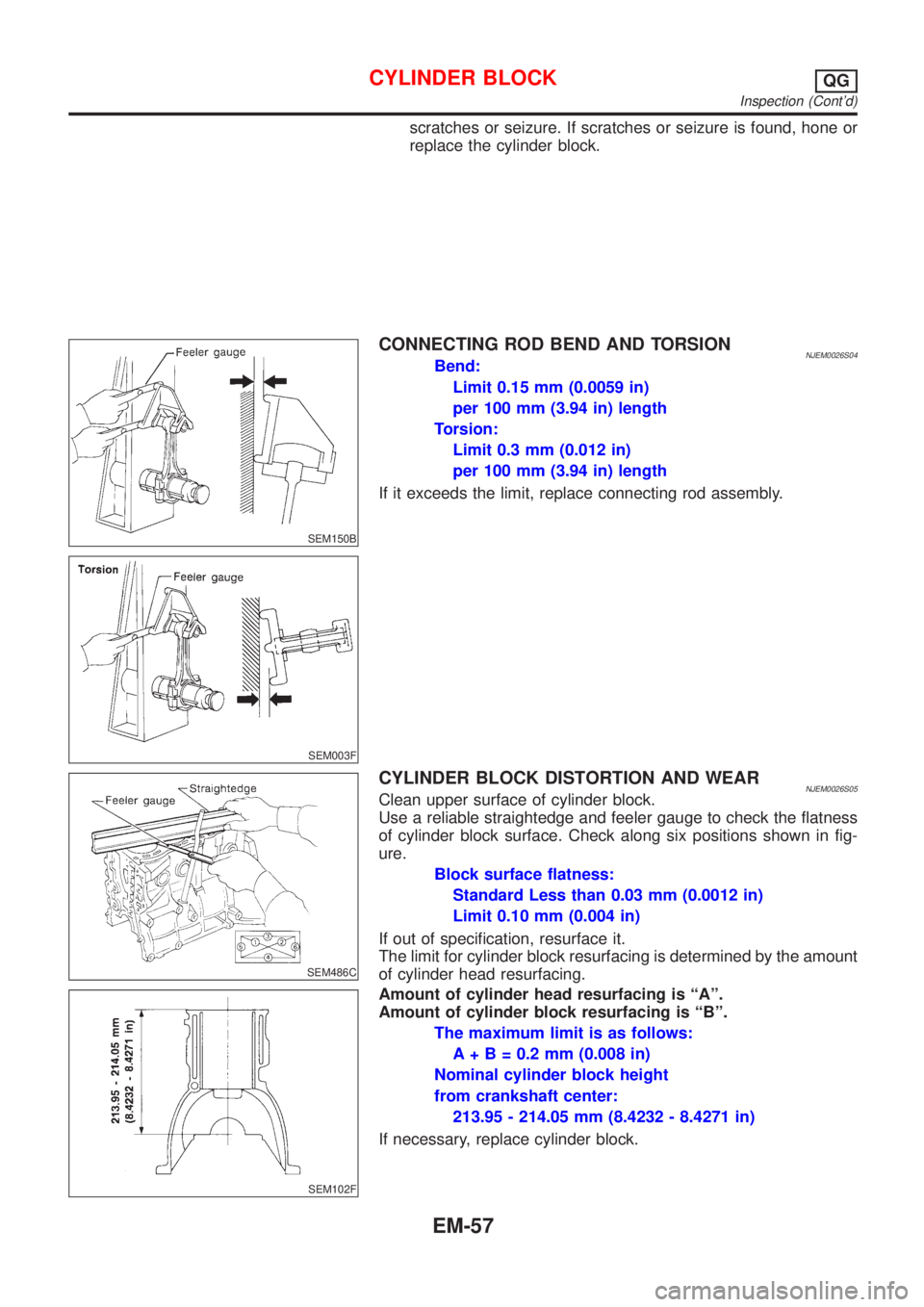
SEM150B
CONNECTING ROD BEND AND TORSIONNJEM0026S04Bend:
Limit 0.15 mm (0.0059 in)
per 100 mm (3.94 in) length
Torsion:
Limit 0.3 mm (0.012 in)
per 100 mm (3.94 in) length
If it exceeds the limit, replace connecting rod assembly.
SEM003F
SEM486C
CYLINDER BLOCK DISTORTION AND WEARNJEM0026S05Clean upper surface of cylinder block.
Use a reliable straightedge and feeler gauge to check the flatness
of cylinder block surface. Check along six positions shown in fig-
ure.
Block surface flatness:
Standard Less than 0.03 mm (0.0012 in)
Limit 0.10 mm (0.004 in)
If out of specification, resurface it.
The limit for cylinder block resurfacing is determined by the amount
of cylinder head resurfacing.
SEM102F
Amount of cylinder head resurfacing is ªAº.
Amount of cylinder block resurfacing is ªBº.
The maximum limit is as follows:
A + B = 0.2 mm (0.008 in)
Nominal cylinder block height
from crankshaft center:
213.95 - 214.05 mm (8.4232 - 8.4271 in)
If necessary, replace cylinder block.
CYLINDER BLOCKQG
Inspection (Cont'd)
EM-57
Page 2201 of 2898
Belt DeflectionNJEM0045Unit: mm (in)
Applied engineUsed belt deflection
Deflection of new belt
LimitDeflection after adjust-
ment
AlternatorWith air conditioner
compressorQG15´18DE 8.1 (0.319)5.3 - 5.7
(0.209 - 0.224)4.5 - 5.0
(0.177 - 0.197)
Without air conditioner
compressorQG15´18DE 10.2 (0.402)6.5 - 7.0
(0.256 - 0.276)5.5 - 6.1
(0.217 - 0.240)
Power steering oil pumpSedan with QG15DE 8.5 (0.335)5.2 - 5.8
(0.205 - 0.228)4.6 - 5.2
(0.181 - 0.205)
Except for Sedan with
QG15DE7.1 (0.280)4.4 - 4.9
(0.173 - 0.193)3.9 - 4.4
(0.154 - 0.173)
Applied pushing force 98 N (10 kg, 22 lb)
Spark PlugNJEM0046
NGK Champion
TypeStandard BKR5E-11 RC10YC4
Hot BKR4E-11 Ð
Cold BKR6E-11 Ð
Plug gap mm (in)1.0 - 1.1 (0.039 - 0.043)
Cylinder HeadNJEM0030Unit: mm (in)
Standard Limit
Head surface flatness Less than 0.03 (0.0012) 0.1 (0.004)
Height 117.8 - 118.0 (4.638 - 4.646) Ð
SERVICE DATA AND SPECIFICATIONS (SDS)QG
Belt Deflection
EM-67
Page 2202 of 2898
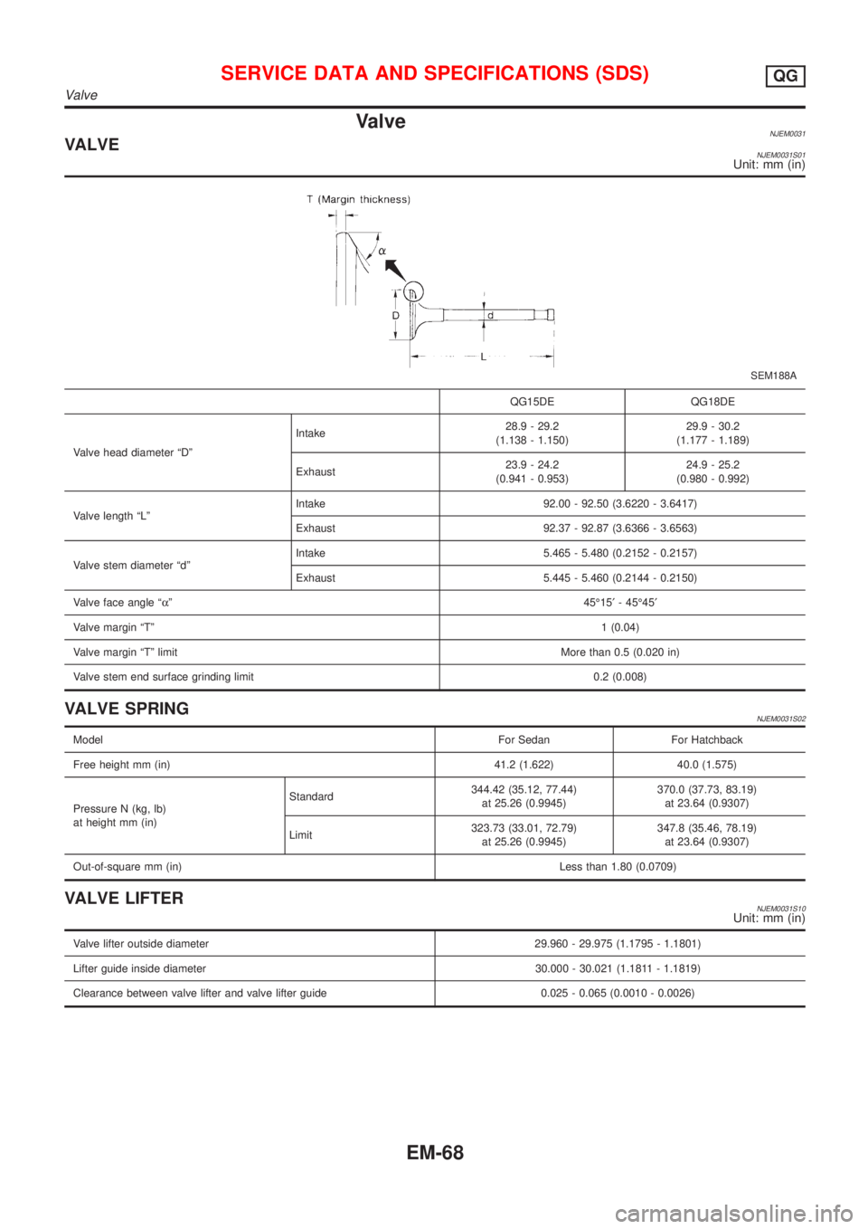
ValveNJEM0031VALVENJEM0031S01Unit: mm (in)
SEM188A
QG15DE QG18DE
Valve head diameter ªDºIntake28.9 - 29.2
(1.138 - 1.150)29.9 - 30.2
(1.177 - 1.189)
Exhaust23.9 - 24.2
(0.941 - 0.953)24.9 - 25.2
(0.980 - 0.992)
Valve length ªLºIntake 92.00 - 92.50 (3.6220 - 3.6417)
Exhaust 92.37 - 92.87 (3.6366 - 3.6563)
Valve stem diameter ªdºIntake 5.465 - 5.480 (0.2152 - 0.2157)
Exhaust 5.445 - 5.460 (0.2144 - 0.2150)
Valve face angle ªaº45É15¢- 45É45¢
Valve margin ªTº1 (0.04)
Valve margin ªTº limitMore than 0.5 (0.020 in)
Valve stem end surface grinding limit 0.2 (0.008)
VALVE SPRINGNJEM0031S02
ModelFor Sedan For Hatchback
Free height mm (in) 41.2 (1.622) 40.0 (1.575)
Pressure N (kg, lb)
at height mm (in)Standard344.42 (35.12, 77.44)
at 25.26 (0.9945)370.0 (37.73, 83.19)
at 23.64 (0.9307)
Limit323.73 (33.01, 72.79)
at 25.26 (0.9945)347.8 (35.46, 78.19)
at 23.64 (0.9307)
Out-of-square mm (in)Less than 1.80 (0.0709)
VALVE LIFTERNJEM0031S10Unit: mm (in)
Valve lifter outside diameter 29.960 - 29.975 (1.1795 - 1.1801)
Lifter guide inside diameter 30.000 - 30.021 (1.1811 - 1.1819)
Clearance between valve lifter and valve lifter guide 0.025 - 0.065 (0.0010 - 0.0026)
SERVICE DATA AND SPECIFICATIONS (SDS)QG
Valve
EM-68
Page 2206 of 2898
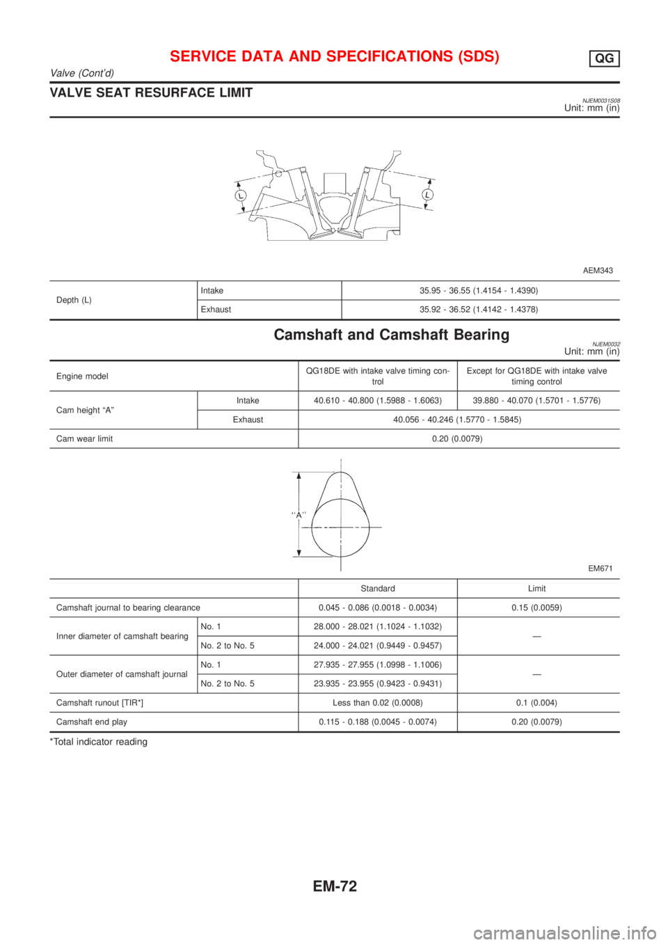
VALVE SEAT RESURFACE LIMITNJEM0031S08Unit: mm (in)
AEM343
Depth (L)Intake 35.95 - 36.55 (1.4154 - 1.4390)
Exhaust 35.92 - 36.52 (1.4142 - 1.4378)
Camshaft and Camshaft BearingNJEM0032Unit: mm (in)
Engine modelQG18DE with intake valve timing con-
trolExcept for QG18DE with intake valve
timing control
Cam height ªAºIntake 40.610 - 40.800 (1.5988 - 1.6063) 39.880 - 40.070 (1.5701 - 1.5776)
Exhaust 40.056 - 40.246 (1.5770 - 1.5845)
Cam wear limit0.20 (0.0079)
EM671
Standard Limit
Camshaft journal to bearing clearance 0.045 - 0.086 (0.0018 - 0.0034) 0.15 (0.0059)
Inner diameter of camshaft bearingNo. 1 28.000 - 28.021 (1.1024 - 1.1032)
Ð
No. 2 to No. 5 24.000 - 24.021 (0.9449 - 0.9457)
Outer diameter of camshaft journalNo. 1 27.935 - 27.955 (1.0998 - 1.1006)
Ð
No. 2 to No. 5 23.935 - 23.955 (0.9423 - 0.9431)
Camshaft runout [TIR*] Less than 0.02 (0.0008) 0.1 (0.004)
Camshaft end play 0.115 - 0.188 (0.0045 - 0.0074) 0.20 (0.0079)
*Total indicator reading
SERVICE DATA AND SPECIFICATIONS (SDS)QG
Valve (Cont'd)
EM-72
Page 2207 of 2898
Cylinder BlockNJEM0033Unit: mm (in)
SEM171D
QG15DE QG18DE
Limit
Standard
Surface flatness Less than 0.03 (0.0012) 0.1 (0.004)
Height ªHº (nominal) 213.95 - 214.05 (8.4232 - 8.4271) Ð
Cylinder bore
inner diameterStandardGrade No. 173.600 - 73.610 (2.8976 -
2.8976)80.000 - 80.010 (3.1496 -
3.1500)
0.2 (0.008) Grade No. 273.610 - 73.620 (2.8980 -
2.8984)80.010 - 80.020 (3.1500 -
3.1504)
Grade No. 373.620 - 73.630 (2.8984 -
2.8988)80.020 - 80.030 (3.1504 -
3.1508)
Out-of-round (X þ Y) Less than 0.015 (0.0006) Ð
Taper (A þ B) Less than 0.01 (0.0004) Ð
Difference in inner diameter between cylinders 0.05 (0.0020) 0.2 (0.008)
SERVICE DATA AND SPECIFICATIONS (SDS)QG
Cylinder Block
EM-73
Page 2256 of 2898
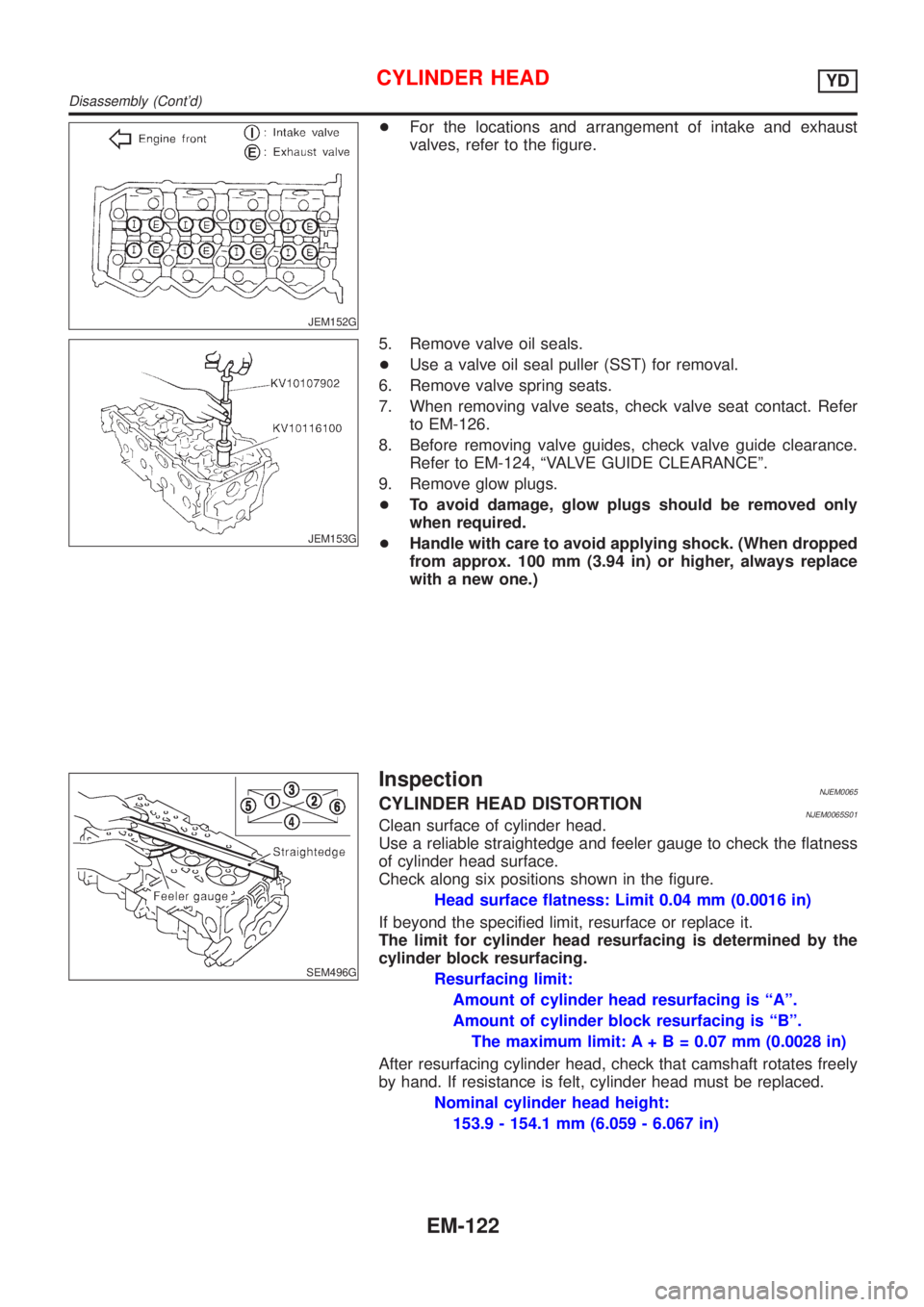
JEM152G
+For the locations and arrangement of intake and exhaust
valves, refer to the figure.
JEM153G
5. Remove valve oil seals.
+Use a valve oil seal puller (SST) for removal.
6. Remove valve spring seats.
7. When removing valve seats, check valve seat contact. Refer
to EM-126.
8. Before removing valve guides, check valve guide clearance.
Refer to EM-124, ªVALVE GUIDE CLEARANCEº.
9. Remove glow plugs.
+To avoid damage, glow plugs should be removed only
when required.
+Handle with care to avoid applying shock. (When dropped
from approx. 100 mm (3.94 in) or higher, always replace
with a new one.)
SEM496G
InspectionNJEM0065CYLINDER HEAD DISTORTIONNJEM0065S01Clean surface of cylinder head.
Use a reliable straightedge and feeler gauge to check the flatness
of cylinder head surface.
Check along six positions shown in the figure.
Head surface flatness: Limit 0.04 mm (0.0016 in)
If beyond the specified limit, resurface or replace it.
The limit for cylinder head resurfacing is determined by the
cylinder block resurfacing.
Resurfacing limit:
Amount of cylinder head resurfacing is ªAº.
Amount of cylinder block resurfacing is ªBº.
The maximum limit: A+ B = 0.07 mm (0.0028 in)
After resurfacing cylinder head, check that camshaft rotates freely
by hand. If resistance is felt, cylinder head must be replaced.
Nominal cylinder head height:
153.9 - 154.1 mm (6.059 - 6.067 in)
CYLINDER HEADYD
Disassembly (Cont'd)
EM-122
Page 2257 of 2898
CAMSHAFT VISUAL CHECKNJEM0065S02Check camshaft for scratches, seizure and wear.
JEM161G
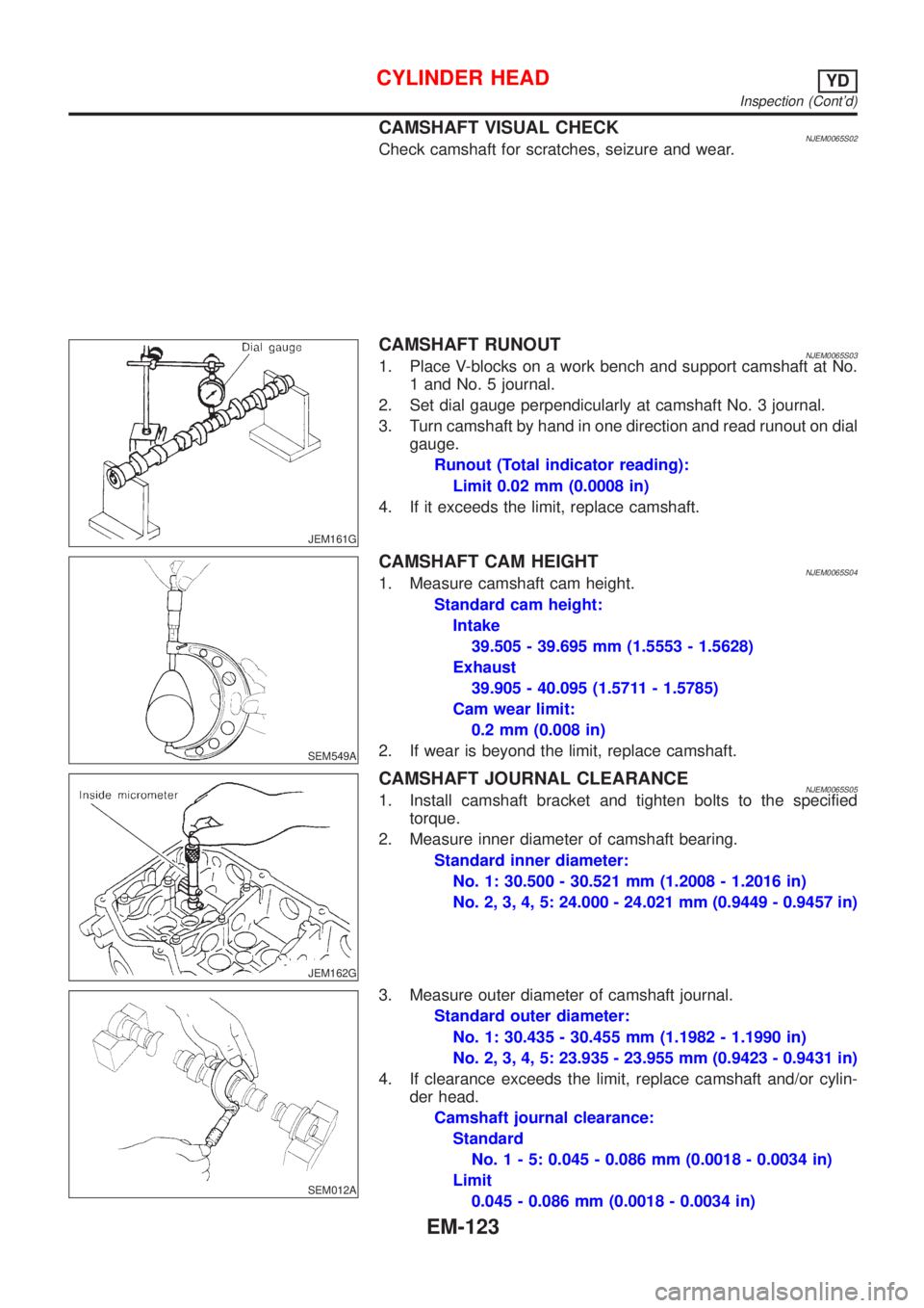
CAMSHAFT RUNOUTNJEM0065S031. Place V-blocks on a work bench and support camshaft at No.
1 and No. 5 journal.
2. Set dial gauge perpendicularly at camshaft No. 3 journal.
3. Turn camshaft by hand in one direction and read runout on dial
gauge.
Runout (Total indicator reading):
Limit 0.02 mm (0.0008 in)
4. If it exceeds the limit, replace camshaft.
SEM549A
CAMSHAFT CAM HEIGHTNJEM0065S041. Measure camshaft cam height.
Standard cam height:
Intake
39.505 - 39.695 mm (1.5553 - 1.5628)
Exhaust
39.905 - 40.095 (1.5711 - 1.5785)
Cam wear limit:
0.2 mm (0.008 in)
2. If wear is beyond the limit, replace camshaft.
JEM162G
CAMSHAFT JOURNAL CLEARANCENJEM0065S051. Install camshaft bracket and tighten bolts to the specified
torque.
2. Measure inner diameter of camshaft bearing.
Standard inner diameter:
No. 1: 30.500 - 30.521 mm (1.2008 - 1.2016 in)
No. 2, 3, 4, 5: 24.000 - 24.021 mm (0.9449 - 0.9457 in)
SEM012A
3. Measure outer diameter of camshaft journal.
Standard outer diameter:
No. 1: 30.435 - 30.455 mm (1.1982 - 1.1990 in)
No. 2, 3, 4, 5: 23.935 - 23.955 mm (0.9423 - 0.9431 in)
4. If clearance exceeds the limit, replace camshaft and/or cylin-
der head.
Camshaft journal clearance:
Standard
No.1-5:0.045 - 0.086 mm (0.0018 - 0.0034 in)
Limit
0.045 - 0.086 mm (0.0018 - 0.0034 in)
CYLINDER HEADYD
Inspection (Cont'd)
EM-123
Page 2262 of 2898
SEM188A
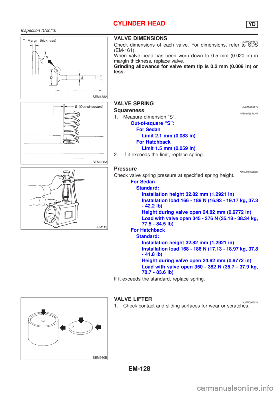
VALVE DIMENSIONSNJEM0065S12Check dimensions of each valve. For dimensions, refer to SDS
(EM-161).
When valve head has been worn down to 0.5 mm (0.020 in) in
margin thickness, replace valve.
Grinding allowance for valve stem tip is 0.2 mm (0.008 in) or
less.
SEM288A
VALVE SPRINGNJEM0065S13SquarenessNJEM0065S13011. Measure dimension ªSº.
Out-of-square ªSº:
For Sedan
Limit 2.1 mm (0.083 in)
For Hatchback
Limit 1.5 mm (0.059 in)
2. If it exceeds the limit, replace spring.
EM113
PressureNJEM0065S1302Check valve spring pressure at specified spring height.
For Sedan
Standard:
Installation height 32.82 mm (1.2921 in)
Installation load 166 - 188 N (16.93 - 19.17 kg, 37.3
- 42.2 lb)
Height during valve open 24.82 mm (0.9772 in)
Load with valve open 345 - 376 N (35.18 - 38.34 kg,
77.5 - 84.5 lb)
For Hatchback
Standard:
Installation height 32.82 mm (1.2921 in)
Installation load 168 - 186 N (17.13 - 18.97 kg, 37.8
- 41.8 lb)
Height during valve open 24.82 mm (0.9772 in)
Load with valve open 350 - 382 N (35.7 - 37.9 kg,
78.7 - 83.6 lb)
If it exceeds the standard, replace spring.
SEM960E
VALVE LIFTERNJEM0065S141. Check contact and sliding surfaces for wear or scratches.
CYLINDER HEADYD
Inspection (Cont'd)
EM-128