2001 NISSAN ALMERA height
[x] Cancel search: heightPage 2505 of 2898
Seat, rear ................................................... BT-60
Self-diagnostic results ....................... EC-74, 628
Shift control components (M/T) .... MT-32, 56, 94
Shift fork (M/T) .............................. MT-32, 56, 94
Shift lever .................................................. MT-29
Shift lock system ...................................... AT-343
Shift schedule .......................................... AT-470
Shift solenoid valve A (A/T) ..... AT-204, 209, 222
Shift solenoid valve B (A/T) ............. AT-204, 209
Shock absorber (front) .............................. SU-10
Shock absorber (rear) ............................... SU-21
Side air bag ........................................ RS-36, 38
Side trim .................................................... BT-31
Spare tire size ............................................ GI-43
Speedometer ........................................... EL-144
Spiral cable ............................................... RS-29
Spot lamp ................................................ EL-141
Spring (Wheelarch) height .......................... SU-6
Stabilizer bar (front) ................................... SU-11
Stall test (A/T) ............................................ AT-80
Standardized relay ....................................... EL-8
Start signal ...................................... EC-557, 823
Starter ....................................................... SC-18
Starting system ......................................... SC-13
Steering linkage ......................................... ST-16
Steering switch .......................................... EL-59
Steering wheel and column ....................... ST-11
Steering wheel play ..................................... ST-6
Steering wheel turning force ....................... ST-8
Stop lamp .................................................. EL-85
Striking rod (M/T) .......................... MT-32, 56, 94
Strut (front) .................................................. SU-9
Strut (rear) ................................................. SU-20
Sub-gear (M/T) ................................... MT-31, 55
Sunroof, electric ....................................... EL-292
Sunroof ...................................................... BT-63
Super lock ................................................ EL-349
Supplemental Restraint System ............... RS-20
Supplemental restraint system - Wiring
diagram .................................................. RS-53
Swirl control valve control solenoid
valve ............................................ EC-399, 475
Symbols and abbreviations ........................ GI-10
Symptom matrix chart ..................... EC-155, 646
Synchronizer (M/T) ....................... MT-31, 55, 93
System readiness test (SRT) code ........... EC-62
T
TCM circuit diagram ................................... AT-17
TCM inspection table ............................... AT-119
TFTS - Wiring diagram ........................... EC-315
TP/SW - Wiring diagram ................. EC-387, 521
TPS - Wiring diagram ............................. EC-210
TURN - Wiring diagram ........................... EL-103
Tachometer .............................................. EL-144
Tail lamp .................................................... EL-81
Tank fuel temperature sensor ................. EC-313
Thermostat .......................................... LC-15, 41Three way catalyst precautions ................... GI-6
Three way catalyst .................................. EC-359
Throttle position sensor (TPS) ................ EC-207
Throttle position sensor
adjustment ................................... EC-100, 128
Throttle position switch ........... AT-141, 267, 341,
EC-385, 520
Throwout bearing - See Clutch release
bearing ............................................. CL-17, 20
Tie-rod ball joints ....................................... ST-20
Tie-rod ........................................................ ST-16
Tightening torque of standard bolts ........... GI-49
Timing chain ....................................... EM-23, 94
Tire size ...................................................... GI-43
Torque converter installation .................... AT-355
Tow truck towing ........................................ GI-47
Transmission case (M/T) .............. MT-30, 54, 92
Tread-FR&RR (Dimensions) ...................... GI-43
Trim ............................................................ BT-31
Trouble diagnoses ...................................... GI-31
Trunk lid finisher ........................................ BT-45
Trunk lid opener - See Trunk lid ................ BT-10
Trunk lid trim .............................................. BT-45
Trunk lid ..................................................... BT-10
Trunk room lamp ..................................... EL-141
Trunk room trim ......................................... BT-45
Turn signal lamp ........................................ EL-96
Two trip detection logic ............................. EC-59
Two-pole lift ................................................ GI-46
U
Under body ................................................ BT-80
V
VSS - Wiring diagram ..................... EC-372, 701
Vacuum hose (brake system) ................... BR-22
Vacuum hose drawing (Engine control) .... EC-30
Vacuum pump ........................................... BR-23
Valve clearance ................................ EM-44, 133
Valve guide ....................................... EM-39, 124
Valve lifter ................................................. EM-43
Valve seat ......................................... EM-41, 126
Valve spring ...................................... EM-42, 128
Vehicle speed sensor (VSS) ........... EC-370, 701
Viscosity number (SAE) ............................ MA-17
Viscous coupling (FF M/T) ........................ MT-93
W
WARN - Wiring diagram .......................... EL-190
WIP/R - Wiring diagram .................. EL-225, 227
WIPER - Wiring diagram ................. EL-217, 220
Warning chime ......................................... EL-197
Warning lamps ......................................... EL-184
Washer, front ........................................... EL-215
ALPHABETICAL INDEX
IDX-7
Page 2506 of 2898

Water pump ......................................... LC-14, 39
Water temperature gauge ........................ EL-144
Weatherstrip - See Exterior ....................... BT-47
Wheel alignment (rear) ............................. SU-18
Wheel bearing (front) .................................. AX-3
Wheel bearing (rear) ................................. AX-23
Wheel hub (front) ........................................ AX-5
Wheel hub (rear) ....................................... AX-24
Wheel sensors (ABS) ............................... BR-97
Wheelarch height ........................................ SU-6
Wheelbase (Dimensions) ........................... GI-43
Wide open & closed throttle positionswitch ................................................... EC-207
Width (Dimensions) .................................... GI-43
Window, rear .............................................. BT-71
Windshield ................................................. BT-71
Wiper, front .............................................. EL-215
Wiring diagram (cell code) list ................. EL-575
Wiring diagrams .......................................... GI-11
Withdrawal lever (clutch) ..................... CL-17, 20
Wrist pin -
See Piston pin inspection ............. EM-56, 145
ALPHABETICAL INDEX
IDX-8
Page 2529 of 2898
SLC904
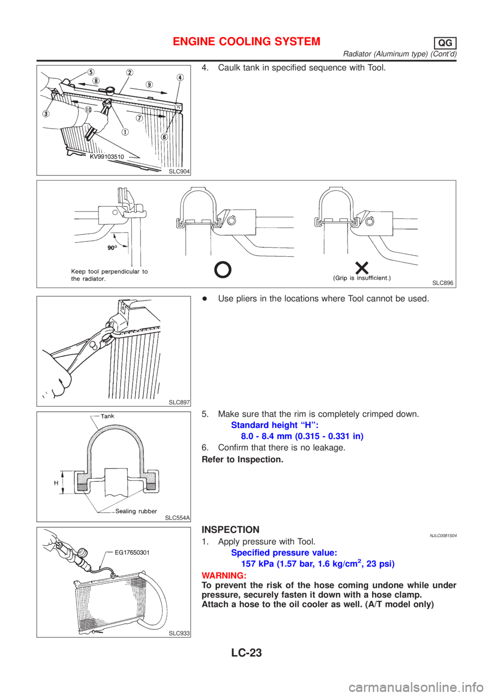
4. Caulk tank in specified sequence with Tool.
SLC896
SLC897
+Use pliers in the locations where Tool cannot be used.
SLC554A
5. Make sure that the rim is completely crimped down.
Standard height ªHº:
8.0 - 8.4 mm (0.315 - 0.331 in)
6. Confirm that there is no leakage.
Refer to Inspection.
SLC933
INSPECTIONNJLC0081S041. Apply pressure with Tool.
Specified pressure value:
157 kPa (1.57 bar, 1.6 kg/cm
2, 23 psi)
WARNING:
To prevent the risk of the hose coming undone while under
pressure, securely fasten it down with a hose clamp.
Attach a hose to the oil cooler as well. (A/T model only)
ENGINE COOLING SYSTEMQG
Radiator (Aluminum type) (Cont'd)
LC-23
Page 2576 of 2898
Special Service ToolsNJMT0030
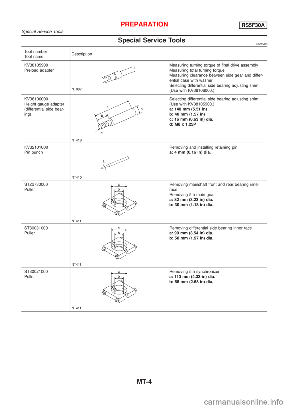
Tool number
Tool nameDescription
KV38105900
Preload adapter
NT087
Measuring turning torque of final drive assembly
Measuring total turning torque
Measuring clearance between side gear and differ-
ential case with washer
Selecting differential side bearing adjusting shim
(Use with KV38106000.)
KV38106000
Height gauge adapter
(differential side bear-
ing)
NT418
Selecting differential side bearing adjusting shim
(Use with KV38105900.)
a: 140 mm (5.51 in)
b: 40 mm (1.57 in)
c: 16 mm (0.63 in) dia.
d: M8 x 1.25P
KV32101000
Pin punch
NT410
Removing and installing retaining pin
a: 4 mm (0.16 in) dia.
ST22730000
Puller
NT411
Removing mainshaft front and rear bearing inner
race
Removing 5th main gear
a: 82 mm (3.23 in) dia.
b: 30 mm (1.18 in) dia.
ST30031000
Puller
NT411
Removing differential side bearing inner race
a: 90 mm (3.54 in) dia.
b: 50 mm (1.97 in) dia.
ST30021000
Puller
NT411
Removing 5th synchronizer
a: 110 mm (4.33 in) dia.
b: 68 mm (2.68 in) dia.
PREPARATIONRS5F30A
Special Service Tools
MT-4
Page 2579 of 2898
Special Service ToolsNJMT0032
Tool number
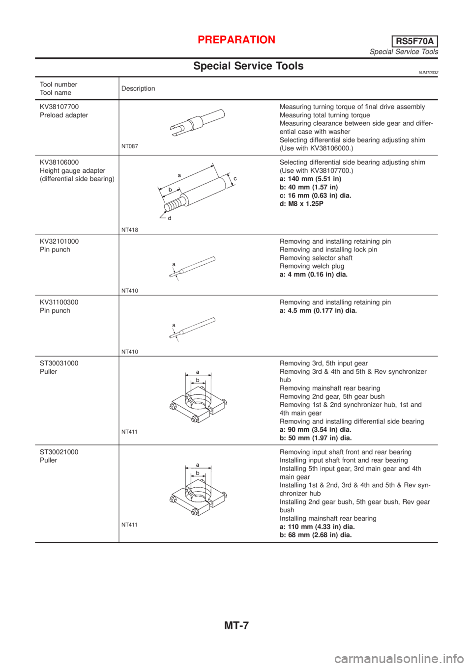
Tool nameDescription
KV38107700
Preload adapter
NT087
Measuring turning torque of final drive assembly
Measuring total turning torque
Measuring clearance between side gear and differ-
ential case with washer
Selecting differential side bearing adjusting shim
(Use with KV38106000.)
KV38106000
Height gauge adapter
(differential side bearing)
NT418
Selecting differential side bearing adjusting shim
(Use with KV38107700.)
a: 140 mm (5.51 in)
b: 40 mm (1.57 in)
c: 16 mm (0.63 in) dia.
d: M8 x 1.25P
KV32101000
Pin punch
NT410
Removing and installing retaining pin
Removing and installing lock pin
Removing selector shaft
Removing welch plug
a: 4 mm (0.16 in) dia.
KV31100300
Pin punch
NT410
Removing and installing retaining pin
a: 4.5 mm (0.177 in) dia.
ST30031000
Puller
NT411
Removing 3rd, 5th input gear
Removing 3rd & 4th and 5th & Rev synchronizer
hub
Removing mainshaft rear bearing
Removing 2nd gear, 5th gear bush
Removing 1st & 2nd synchronizer hub, 1st and
4th main gear
Removing and installing differential side bearing
a: 90 mm (3.54 in) dia.
b: 50 mm (1.97 in) dia.
ST30021000
Puller
NT411
Removing input shaft front and rear bearing
Installing input shaft front and rear bearing
Installing 5th input gear, 3rd main gear and 4th
main gear
Installing 1st & 2nd, 3rd & 4th and 5th & Rev syn-
chronizer hub
Installing 2nd gear bush, 5th gear bush, Rev gear
bush
Installing mainshaft rear bearing
a: 110 mm (4.33 in) dia.
b: 68 mm (2.68 in) dia.
PREPARATIONRS5F70A
Special Service Tools
MT-7
Page 2820 of 2898
SEL022Z
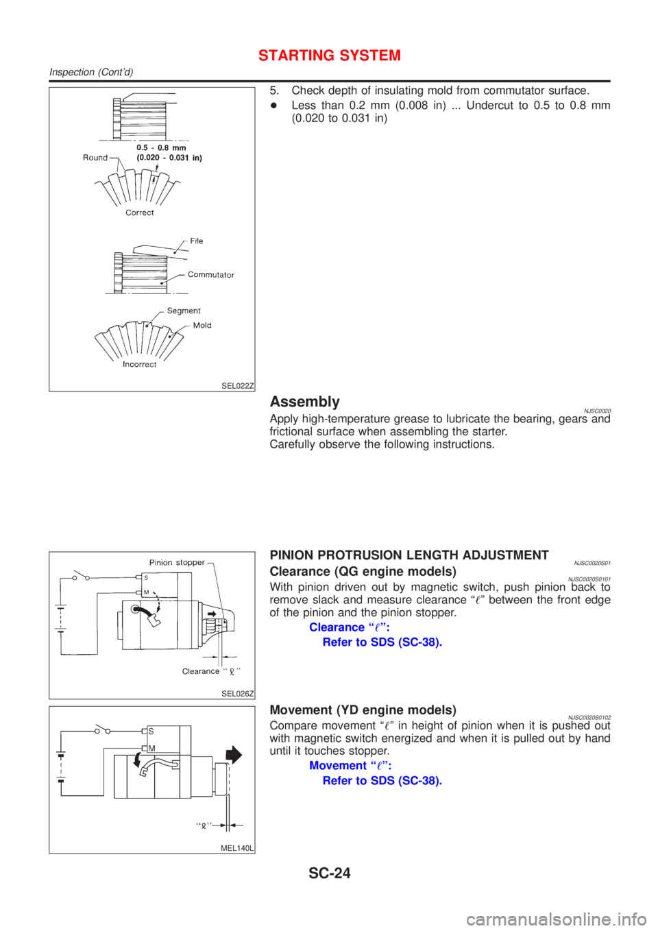
5. Check depth of insulating mold from commutator surface.
+Less than 0.2 mm (0.008 in) ... Undercut to 0.5 to 0.8 mm
(0.020 to 0.031 in)
AssemblyNJSC0020Apply high-temperature grease to lubricate the bearing, gears and
frictional surface when assembling the starter.
Carefully observe the following instructions.
SEL026Z
PINION PROTRUSION LENGTH ADJUSTMENTNJSC0020S01Clearance (QG engine models)NJSC0020S0101With pinion driven out by magnetic switch, push pinion back to
remove slack and measure clearance ª!º between the front edge
of the pinion and the pinion stopper.
Clearance ª!º:
Refer to SDS (SC-38).
MEL140L
Movement (YD engine models)NJSC0020S0102Compare movement ª!º in height of pinion when it is pushed out
with magnetic switch energized and when it is pulled out by hand
until it touches stopper.
Movement ª!º:
Refer to SDS (SC-38).
STARTING SYSTEM
Inspection (Cont'd)
SC-24
Page 2834 of 2898
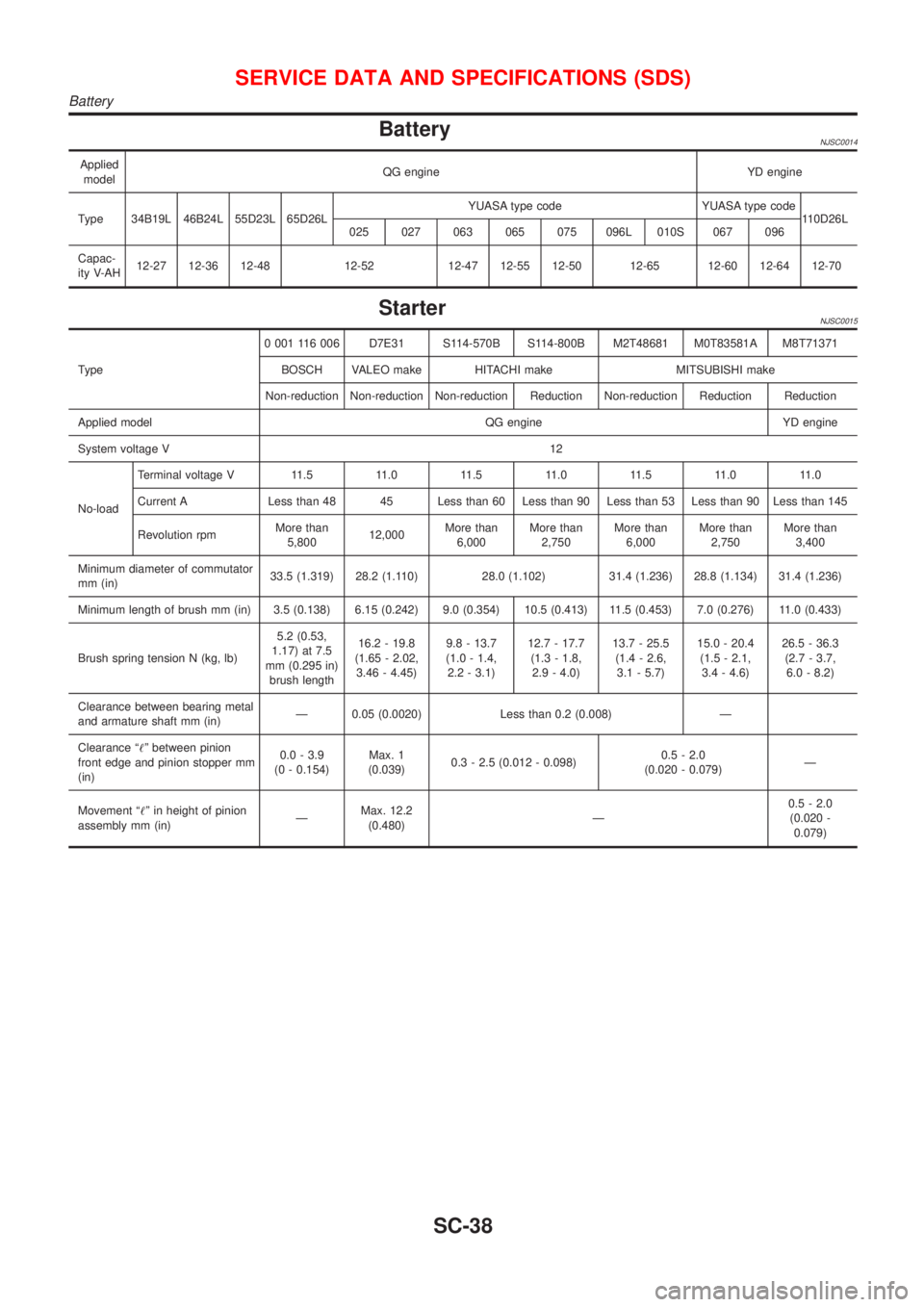
BatteryNJSC0014
Applied
modelQG engine YD engine
Type 34B19L 46B24L 55D23L 65D26LYUASA type code YUASA type code
110D26L
025 027 063 065 075 096L 010S 067 096
Capac-
ity V-AH12-27 12-36 12-48 12-52 12-47 12-55 12-50 12-65 12-60 12-64 12-70
StarterNJSC0015
Type0 001 116 006 D7E31 S114-570B S114-800B M2T48681 M0T83581A M8T71371
BOSCH VALEO make HITACHI make MITSUBISHI make
Non-reduction Non-reduction Non-reduction Reduction Non-reduction Reduction Reduction
Applied model QG engine YD engine
System voltage V12
No-loadTerminal voltage V 11.5 11.0 11.5 11.0 11.5 11.0 11.0
Current A Less than 48 45 Less than 60 Less than 90 Less than 53 Less than 90 Less than 145
Revolution rpmMore than
5,80012,000More than
6,000More than
2,750More than
6,000More than
2,750More than
3,400
Minimum diameter of commutator
mm (in)33.5 (1.319) 28.2 (1.110) 28.0 (1.102) 31.4 (1.236) 28.8 (1.134) 31.4 (1.236)
Minimum length of brush mm (in) 3.5 (0.138) 6.15 (0.242) 9.0 (0.354) 10.5 (0.413) 11.5 (0.453) 7.0 (0.276) 11.0 (0.433)
Brush spring tension N (kg, lb)5.2 (0.53,
1.17) at 7.5
mm (0.295 in)
brush length16.2 - 19.8
(1.65 - 2.02,
3.46 - 4.45)9.8 - 13.7
(1.0 - 1.4,
2.2 - 3.1)12.7 - 17.7
(1.3 - 1.8,
2.9 - 4.0)13.7 - 25.5
(1.4 - 2.6,
3.1 - 5.7)15.0 - 20.4
(1.5 - 2.1,
3.4 - 4.6)26.5 - 36.3
(2.7 - 3.7,
6.0 - 8.2)
Clearance between bearing metal
and armature shaft mm (in)Ð 0.05 (0.0020) Less than 0.2 (0.008) Ð
Clearance ª!º between pinion
front edge and pinion stopper mm
(in)0.0 - 3.9
(0 - 0.154)Max. 1
(0.039)0.3 - 2.5 (0.012 - 0.098)0.5 - 2.0
(0.020 - 0.079)Ð
Movement ª!º in height of pinion
assembly mm (in)ÐMax. 12.2
(0.480)Ð0.5 - 2.0
(0.020 -
0.079)
SERVICE DATA AND SPECIFICATIONS (SDS)
Battery
SC-38
Page 2873 of 2898
FRONT & REAR SUSPENSION
SECTION
SU
CONTENTS
FRONT SUSPENSION....................................................2
Precautions ..................................................................2
PRECAUTIONS.........................................................2
Preparation ..................................................................2
SPECIAL SERVICE TOOLS........................................2
COMMERCIAL SERVICE TOOLS................................2
Noise, Vibration and Harshness (NVH)
Troubleshooting ...........................................................4
NVH TROUBLESHOOTING CHART............................4
Components.................................................................5
On-vehicle Service.......................................................6
FRONT SUSPENSION PARTS...................................6
BALANCING WHEELS...............................................7
TIRE ROTATION.......................................................7
FRONT WHEEL ALIGNMENT.....................................7
Coil Spring and Shock Absorber .................................9
COMPONENTS.........................................................9
REMOVAL AND INSTALLATION...............................10
DISASSEMBLY........................................................10
INSPECTION...........................................................10
ASSEMBLY............................................................. 11
Stabilizer Bar ............................................................. 11
REMOVAL AND INSTALLATION............................... 11
Transverse Link and Lower Ball Joint .......................12
REMOVAL AND INSTALLATION...............................12
INSPECTION...........................................................13
Service Data and Specifications (SDS).....................14
GENERAL SPECIFICATIONS (FRONT).....................14
FRONT WHEEL ALIGNMENT (UNLADEN*1).............14
LOWER BALL JOINT...............................................14
WHEELARCH HEIGHT (UNLADEN*1).......................15
WHEEL RUNOUT....................................................15
WHEEL BALANCE...................................................15
REAR SUSPENSION.....................................................16
Precautions ................................................................16
PRECAUTIONS.......................................................16
Preparation ................................................................16
COMMERCIAL SERVICE TOOLS..............................16
Noise, Vibration and Harshness (NVH)
Troubleshooting .........................................................16
Components...............................................................17
On-vehicle Service.....................................................18
REAR SUSPENSION PARTS...................................18
REAR WHEEL ALIGNMENT.....................................18
Removal and Installation ...........................................20
REMOVAL...............................................................21
INSTALLATION........................................................21
Coil Spring and Shock Absorber ...............................21
REMOVAL AND INSTALLATION...............................21
DISASSEMBLY........................................................22
INSPECTION...........................................................22
ASSEMBLY.............................................................22
Torsion Beam, Lateral Link and Control Rod ............23
DISASSEMBLY........................................................23
INSPECTION...........................................................23
ASSEMBLY.............................................................23
Service Data and Specifications (SDS).....................25
GENERAL SPECIFICATIONS (REAR).......................25
REAR WHEEL ALIGNMENT (UNLADEN*).................25