Page 1155 of 2898

Diagnostic ProcedureNJEC0353
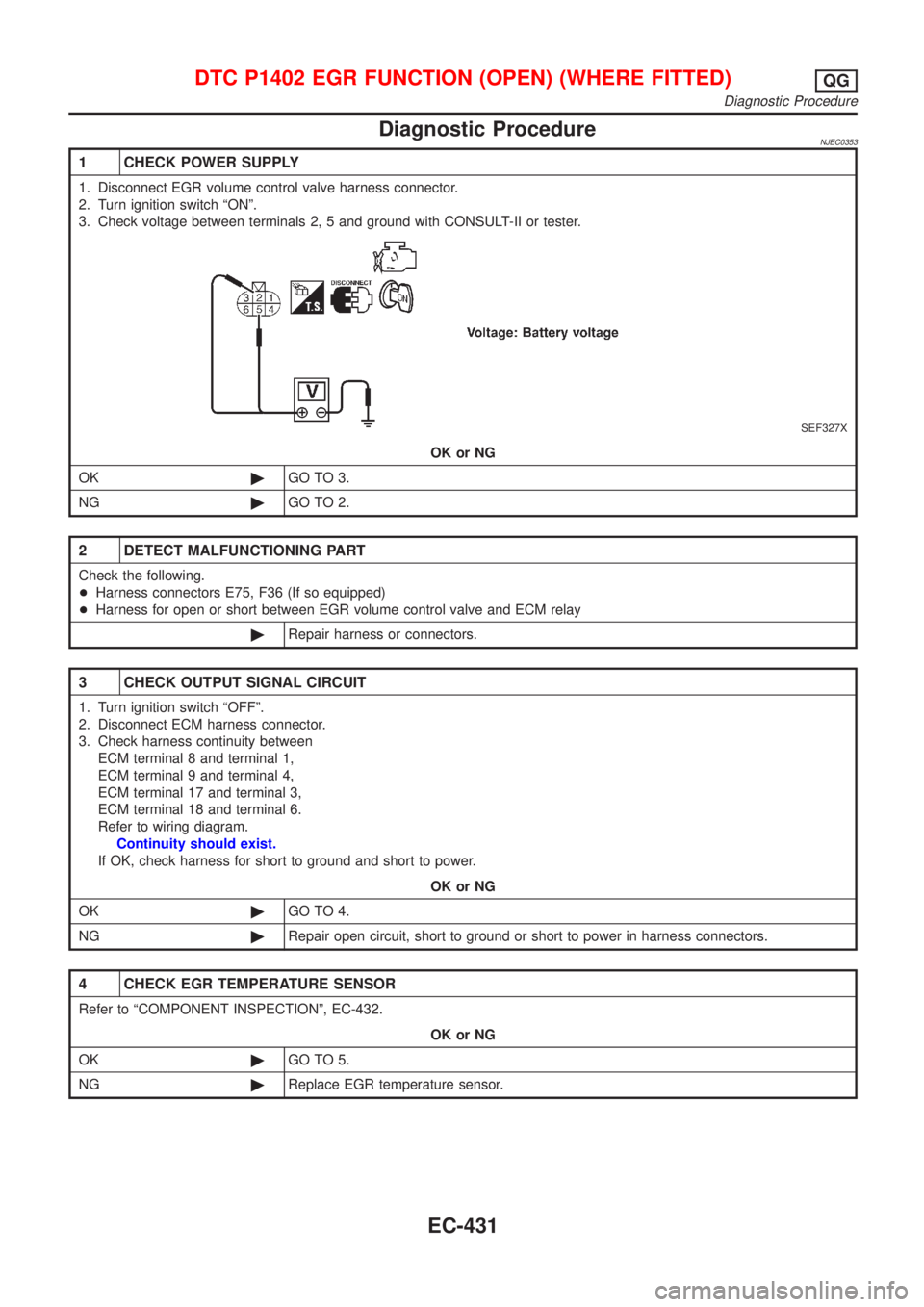
1 CHECK POWER SUPPLY
1. Disconnect EGR volume control valve harness connector.
2. Turn ignition switch ªONº.
3. Check voltage between terminals 2, 5 and ground with CONSULT-II or tester.
SEF327X
OK or NG
OK©GO TO 3.
NG©GO TO 2.
2 DETECT MALFUNCTIONING PART
Check the following.
+Harness connectors E75, F36 (If so equipped)
+Harness for open or short between EGR volume control valve and ECM relay
©Repair harness or connectors.
3 CHECK OUTPUT SIGNAL CIRCUIT
1. Turn ignition switch ªOFFº.
2. Disconnect ECM harness connector.
3. Check harness continuity between
ECM terminal 8 and terminal 1,
ECM terminal 9 and terminal 4,
ECM terminal 17 and terminal 3,
ECM terminal 18 and terminal 6.
Refer to wiring diagram.
Continuity should exist.
If OK, check harness for short to ground and short to power.
OK or NG
OK©GO TO 4.
NG©Repair open circuit, short to ground or short to power in harness connectors.
4 CHECK EGR TEMPERATURE SENSOR
Refer to ªCOMPONENT INSPECTIONº, EC-432.
OK or NG
OK©GO TO 5.
NG©Replace EGR temperature sensor.
DTC P1402 EGR FUNCTION (OPEN) (WHERE FITTED)QG
Diagnostic Procedure
EC-431
Page 1156 of 2898
5 CHECK EGR VOLUME CONTROL VALVE
Refer to ªCOMPONENT INSPECTIONº, EC-432.
OK or NG
OK©GO TO 6.
NG©Replace EGR volume control valve.
6 CHECK INTERMITTENT INCIDENT
Perform ªTROUBLE DIAGNOSIS FOR INTERMITTENT INCIDENTº, EC-177.
©INSPECTION END
SEF611Y
SEF068X
Component InspectionNJEC0354EGR TEMPERATURE SENSORNJEC0354S01Check resistance change and resistance value.
EGR temperature
ÉC (ÉF)Voltage
VResistance
MW
0 (32) 4.56 0.62 - 1.05
50 (122) 2.25 0.065 - 0.094
100 (212) 0.59 0.011 - 0.015
If NG, replace EGR temperature sensor.
DTC P1402 EGR FUNCTION (OPEN) (WHERE FITTED)QG
Diagnostic Procedure (Cont'd)
EC-432
Page 1166 of 2898

SEF206T
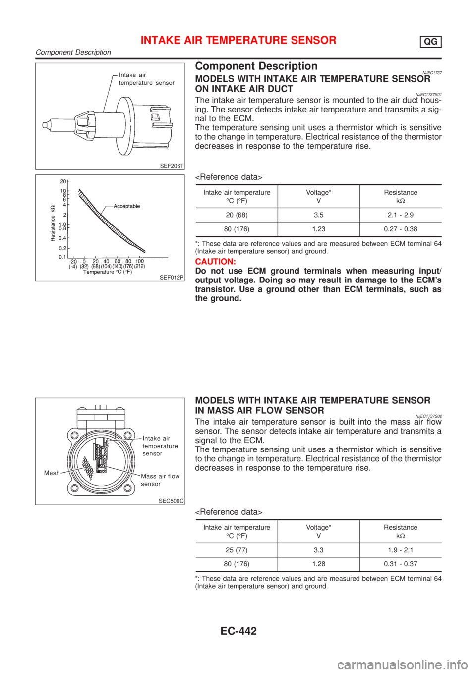
Component DescriptionNJEC1737MODELS WITH INTAKE AIR TEMPERATURE SENSOR
ON INTAKE AIR DUCT
NJEC1737S01The intake air temperature sensor is mounted to the air duct hous-
ing. The sensor detects intake air temperature and transmits a sig-
nal to the ECM.
The temperature sensing unit uses a thermistor which is sensitive
to the change in temperature. Electrical resistance of the thermistor
decreases in response to the temperature rise.
SEF012P
Intake air temperature
ÉC (ÉF)Voltage*
VResistance
kW
20 (68) 3.5 2.1 - 2.9
80 (176) 1.23 0.27 - 0.38
*: These data are reference values and are measured between ECM terminal 64
(Intake air temperature sensor) and ground.
CAUTION:
Do not use ECM ground terminals when measuring input/
output voltage. Doing so may result in damage to the ECM's
transistor. Use a ground other than ECM terminals, such as
the ground.
SEC500C
MODELS WITH INTAKE AIR TEMPERATURE SENSOR
IN MASS AIR FLOW SENSOR
NJEC1737S02The intake air temperature sensor is built into the mass air flow
sensor. The sensor detects intake air temperature and transmits a
signal to the ECM.
The temperature sensing unit uses a thermistor which is sensitive
to the change in temperature. Electrical resistance of the thermistor
decreases in response to the temperature rise.
Intake air temperature
ÉC (ÉF)Voltage*
VResistance
kW
25 (77) 3.3 1.9 - 2.1
80 (176) 1.28 0.31 - 0.37
*: These data are reference values and are measured between ECM terminal 64
(Intake air temperature sensor) and ground.
INTAKE AIR TEMPERATURE SENSORQG
Component Description
EC-442
Page 1167 of 2898
CAUTION:
Do not use ECM ground terminals when measuring input/
output voltage. Doing so may result in damage to the ECM's
transistor. Use a ground other than ECM terminals, such as
the ground.
INTAKE AIR TEMPERATURE SENSORQG
Component Description (Cont'd)
EC-443
Page 1168 of 2898
Wiring DiagramNJEC1738MODELS WITH INTAKE AIR TEMPERATURE SENSOR
IN MASS AIR FLOW SENSOR
NJEC1738S01
HEC948
INTAKE AIR TEMPERATURE SENSORQG
Wiring Diagram
EC-444
Page 1169 of 2898
MODELS WITH INTAKE AIR TEMPERATURE SENSOR
ON INTAKE AIR DUCT
NJEC1738S02
NEF330A
INTAKE AIR TEMPERATURE SENSORQG
Wiring Diagram (Cont'd)
EC-445
Page 1170 of 2898
Diagnostic ProcedureNJEC1739
1 CHECK OVERALL FUNCTION
1. Turn ignition switch ªONº.
2. Check voltage between ECM terminal 64 and ground with CONSULT-II or tester.
SEF004YA
OK or NG
OK©INSPECTION END
NG©GO TO 2.
2 CHECK POWER SUPPLY (Models with intake air temperature sensor on intake air duct)
1. Turn ignition switch ªOFFº.
2. Disconnect intake air temperature sensor harness connector.
SEF602Y
3. Turn ignition switch ªONº.
4. Check voltage between terminal 1 and ground with CONSULT-II or tester.
SEF301X
OK or NG
OK©GO TO 5.
NG©GO TO 4.
INTAKE AIR TEMPERATURE SENSORQG
Diagnostic Procedure
EC-446
Page 1171 of 2898

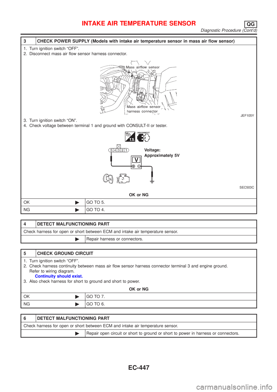
3 CHECK POWER SUPPLY (Models with intake air temperature sensor in mass air flow sensor)
1. Turn ignition switch ªOFFº.
2. Disconnect mass air flow sensor harness connector.
JEF105Y
3. Turn ignition switch ªONº.
4. Check voltage between terminal 1 and ground with CONSULT-II or tester.
SEC503C
OK or NG
OK©GO TO 5.
NG©GO TO 4.
4 DETECT MALFUNCTIONING PART
Check harness for open or short between ECM and intake air temperature sensor.
©Repair harness or connectors.
5 CHECK GROUND CIRCUIT
1. Turn ignition switch ªOFFº.
2. Check harness continuity between mass air flow sensor harness connector terminal 3 and engine ground.
Refer to wiring diagram.
Continuity should exist.
3. Also check harness for short to ground and short to power.
OK or NG
OK©GO TO 7.
NG©GO TO 6.
6 DETECT MALFUNCTIONING PART
Check harness for open or short between ECM and intake air temperature sensor.
©Repair open circuit or short to ground or short to power in harness or connectors.
INTAKE AIR TEMPERATURE SENSORQG
Diagnostic Procedure (Cont'd)
EC-447