Page 1180 of 2898
SEF648Y
SEF011X
Without CONSULT-II
1) Start engine and warm it up to normal operating temperature.
2) Set voltmeter probes between ECM terminal 62 (HO2S1 sig-
nal) and engine ground.
3) Check the following with engine speed held at 2,000 rpm con-
stant under no load.
+The voltage fluctuates between 0 to 0.3V and 0.6 to 1.0V more
than 5 times within 10 seconds.
+The maximum voltage is over 0.6V at least one time.
+The minimum voltage is below 0.3V at least one time.
+The voltage never exceeds 1.0V.
1 time: 0 - 0.3V®0.6 - 1.0V®0 - 0.3V
2 times: 0 - 0.3V®0.6 - 1.0V®0 - 0.3V®0.6 - 1.0V®0-
0.3V
CAUTION:
+Discard any heated oxygen sensor which has been
dropped from a height of more than 0.5 m (19.7 in) onto a
hard surface such as a concrete floor; use a new one.
+Before installing new oxygen sensor, clean exhaust sys-
tem threads using Oxygen Sensor Thread Cleaner tool
and approved anti-seize lubricant.
HEATED OXYGEN SENSOR 1 (FRONT)QG
Component Inspection (Cont'd)
EC-456
Page 1181 of 2898

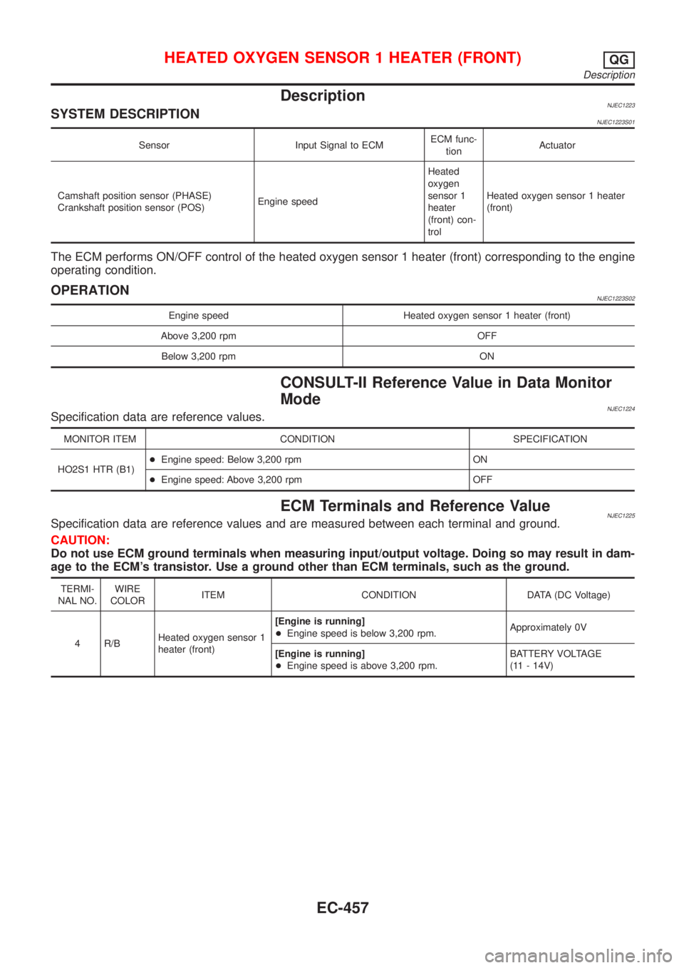
DescriptionNJEC1223SYSTEM DESCRIPTIONNJEC1223S01
Sensor Input Signal to ECMECM func-
tionActuator
Camshaft position sensor (PHASE)
Crankshaft position sensor (POS)Engine speedHeated
oxygen
sensor 1
heater
(front) con-
trolHeated oxygen sensor 1 heater
(front)
The ECM performs ON/OFF control of the heated oxygen sensor 1 heater (front) corresponding to the engine
operating condition.
OPERATIONNJEC1223S02
Engine speed Heated oxygen sensor 1 heater (front)
Above 3,200 rpm OFF
Below 3,200 rpm ON
CONSULT-II Reference Value in Data Monitor
Mode
NJEC1224Specification data are reference values.
MONITOR ITEM CONDITION SPECIFICATION
HO2S1 HTR (B1)+Engine speed: Below 3,200 rpm ON
+Engine speed: Above 3,200 rpm OFF
ECM Terminals and Reference ValueNJEC1225Specification data are reference values and are measured between each terminal and ground.
CAUTION:
Do not use ECM ground terminals when measuring input/output voltage. Doing so may result in dam-
age to the ECM's transistor. Use a ground other than ECM terminals, such as the ground.
TERMI-
NAL NO.WIRE
COLORITEM CONDITION DATA (DC Voltage)
4 R/BHeated oxygen sensor 1
heater (front)[Engine is running]
+Engine speed is below 3,200 rpm.Approximately 0V
[Engine is running]
+Engine speed is above 3,200 rpm.BATTERY VOLTAGE
(11 - 14V)
HEATED OXYGEN SENSOR 1 HEATER (FRONT)QG
Description
EC-457
Page 1182 of 2898
Wiring DiagramNJEC1228SEDAN MODELS AND HATCHBACK MODELS WITH
ECM IN ENGINE COMPARTMENT
NJEC1228S03
HEC852
HEATED OXYGEN SENSOR 1 HEATER (FRONT)QG
Wiring Diagram
EC-458
Page 1183 of 2898
HATCHBACK MODELS WITH ECM IN CABINNJEC1228S04
HEC939
HEATED OXYGEN SENSOR 1 HEATER (FRONT)QG
Wiring Diagram (Cont'd)
EC-459
Page 1184 of 2898
Diagnostic ProcedureNJEC1229
1 CHECK OVERALL FUNCTION
1. Turn ignition switch ªONº.
2. Set the tester probe between ECM terminals 4 [HO2S1 Heater (front) signal] and ground.
3. Start engine and let it idle.
4. Check the voltage under the following conditions.
SEF239Z
OK or NG
OK©INSPECTION END
NG©GO TO 2.
2 CHECK POWER SUPPLY
1. Turn ignition switch ªOFFº.
2. Disconnect heated oxygen sensor 1 (front) harness connector.
SEF012XA
3. Turn ignition switch ªONº.
4. Check voltage between terminal 1 and ground with CONSULT-II or tester.
SEF934X
OK or NG
OK©GO TO 4.
NG©GO TO 3.
HEATED OXYGEN SENSOR 1 HEATER (FRONT)QG
Diagnostic Procedure
EC-460
Page 1185 of 2898

3 DETECT MALFUNCTIONING PART
Check the following.
+Harness connectors F36, E75
+Harness connectors E106, M21 (Sedan), E175, M160 or F113, M169 (Hatchback)
+10A fuse
+Harness for open or short between heated oxygen sensor 1 (front) and fuse
©Repair harness or connectors.
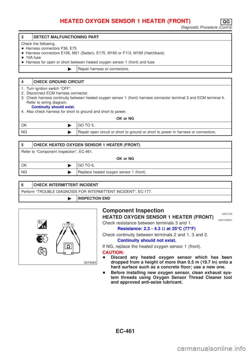
4 CHECK GROUND CIRCUIT
1. Turn ignition switch ªOFFº.
2. Disconnect ECM harness connector.
3. Check harness continuity between heated oxygen sensor 1 (front) harness connector terminal 3 and ECM terminal 4.
Refer to wiring diagram.
Continuity should exist.
4. Also check harness for short to ground and short to power.
OK or NG
OK©GO TO 5.
NG©Repair open circuit or short to ground or short to power in harness or connectors.
5 CHECK HEATED OXYGEN SENSOR 1 HEATER (FRONT)
Refer to ªComponent Inspectionº, EC-461.
OK or NG
OK©GO TO 6.
NG©Replace heated oxygen sensor 1 (front).
6 CHECK INTERMITTENT INCIDENT
Perform ªTROUBLE DIAGNOSIS FOR INTERMITTENT INCIDENTº, EC-177.
©INSPECTION END
SEF935X
Component InspectionNJEC1230HEATED OXYGEN SENSOR 1 HEATER (FRONT)NJEC1230S01Check resistance between terminals 3 and 1.
Resistance: 2.3 - 4.3Wat 25ÉC (77ÉF)
Check continuity between terminals 2 and 1, 3 and 2.
Continuity should not exist.
If NG, replace the heated oxygen sensor 1 (front).
CAUTION:
+Discard any heated oxygen sensor which has been
dropped from a height of more than 0.5 m (19.7 in) onto a
hard surface such as a concrete floor; use a new one.
+Before installing new oxygen sensor, clean exhaust sys-
tem threads using Oxygen Sensor Thread Cleaner tool
and approved anti-seize lubricant.
HEATED OXYGEN SENSOR 1 HEATER (FRONT)QG
Diagnostic Procedure (Cont'd)
EC-461
Page 1186 of 2898

SEF327R
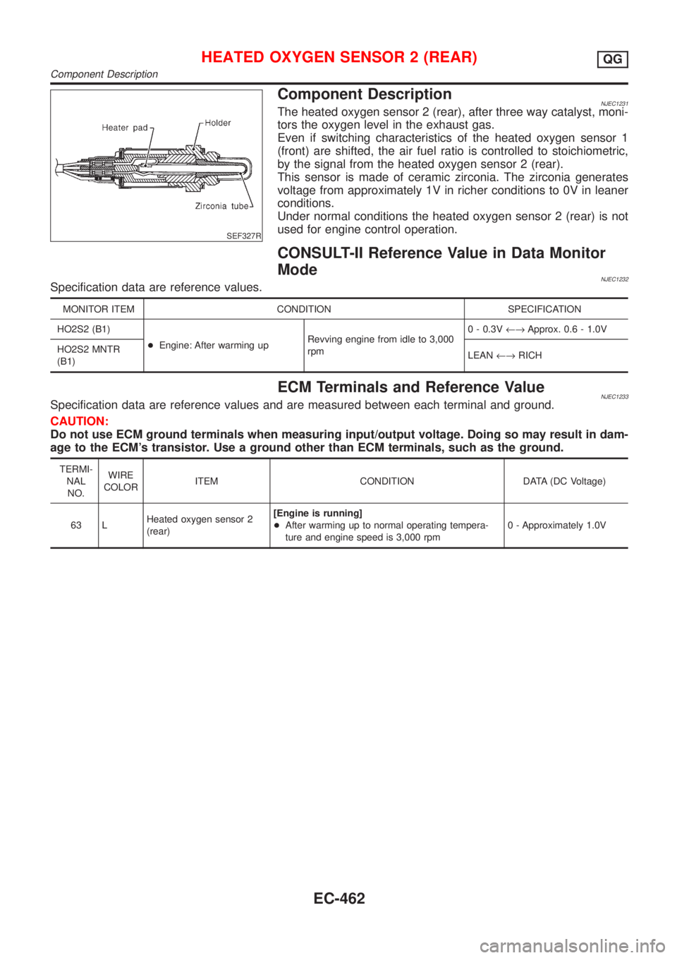
Component DescriptionNJEC1231The heated oxygen sensor 2 (rear), after three way catalyst, moni-
tors the oxygen level in the exhaust gas.
Even if switching characteristics of the heated oxygen sensor 1
(front) are shifted, the air fuel ratio is controlled to stoichiometric,
by the signal from the heated oxygen sensor 2 (rear).
This sensor is made of ceramic zirconia. The zirconia generates
voltage from approximately 1V in richer conditions to 0V in leaner
conditions.
Under normal conditions the heated oxygen sensor 2 (rear) is not
used for engine control operation.
CONSULT-II Reference Value in Data Monitor
Mode
NJEC1232Specification data are reference values.
MONITOR ITEM CONDITION SPECIFICATION
HO2S2 (B1)
+Engine: After warming upRevving engine from idle to 3,000
rpm0 - 0.3V¨Approx. 0.6 - 1.0V
HO2S2 MNTR
(B1)LEAN¨RICH
ECM Terminals and Reference ValueNJEC1233Specification data are reference values and are measured between each terminal and ground.
CAUTION:
Do not use ECM ground terminals when measuring input/output voltage. Doing so may result in dam-
age to the ECM's transistor. Use a ground other than ECM terminals, such as the ground.
TERMI-
NAL
NO.WIRE
COLORITEM CONDITION DATA (DC Voltage)
63 LHeated oxygen sensor 2
(rear)[Engine is running]
+After warming up to normal operating tempera-
ture and engine speed is 3,000 rpm0 - Approximately 1.0V
HEATED OXYGEN SENSOR 2 (REAR)QG
Component Description
EC-462
Page 1187 of 2898
Wiring DiagramNJEC1237SEDAN MODELS AND HATCHBACK MODELS WITH
ECM IN ENGINE COMPARTMENT
NJEC1237S03
HEC853
HEATED OXYGEN SENSOR 2 (REAR)QG
Wiring Diagram
EC-463