2001 NISSAN ALMERA Ignition system
[x] Cancel search: Ignition systemPage 584 of 2898
![NISSAN ALMERA 2001 Service Manual Diagnostic item Diagnostic item is detected when ...Reference
Page
RR RH OUT ABS SOL
[SHORT]+Circuit for rear right outlet solenoid valve is shorted.
(An abnormally high output voltage is entered.)BR- NISSAN ALMERA 2001 Service Manual Diagnostic item Diagnostic item is detected when ...Reference
Page
RR RH OUT ABS SOL
[SHORT]+Circuit for rear right outlet solenoid valve is shorted.
(An abnormally high output voltage is entered.)BR-](/manual-img/5/57348/w960_57348-583.png)
Diagnostic item Diagnostic item is detected when ...Reference
Page
RR RH OUT ABS SOL
[SHORT]+Circuit for rear right outlet solenoid valve is shorted.
(An abnormally high output voltage is entered.)BR-81
RR LH OUT ABS SOL
[SHORT]+Circuit for rear left outlet solenoid valve is shorted.
(An abnormally high output voltage is entered.)BR-81
ABS ACTUATOR RELAY
[ABNORMAL]+Actuator solenoid valve relay is ON, even control unit sends off signal.
+Actuator solenoid valve relay is OFF, even control unit sends on signal.BR-81
ABS MOTOR RELAY
[ABNORMAL]+Circuit for actuator motor is open or shorted.
+Actuator motor relay is stuck.BR-84
BATTERY VOLT
[ABNORMAL]+Power source voltage supplied to ABS control unit is abnormally low. BR-86
CONTROL UNIT+Function of calculation in ABS control unit has failed. BR-88
*1: Be sure to confirm the ABS warning lamp illuminates when the ignition switch is turned ON after repairing the shorted sensor circuit,
but the lamp goes out when driving the vehicle over 30 km/h (19 MPH) for one minute in accordance with SELF-DIAGNOSIS
PROCEDURE.
PBR455D
DATA MONITOR PROCEDURENJBR0093S031. Turn ignition switch OFF.
2. Connect CONSULT-II to data link connector.
3. Turn ignition switch ON.
4. Touch ªSTARTº on CONSULT-II screen.
PBR385C
5. Touch ªABSº.
PST412B
6. Touch ªDATA MONITORº.
7. Touch ªSETTINGº on ªSELECT MONITOR ITEMº screen.
8. Touch ªLONG TIMEº on ªSET RECORDING CONDº screen.
9. Touch ªSTARTº on ªSELECT MONITOR ITEMº.
ON BOARD DIAGNOSTIC SYSTEM DESCRIPTIONABS
CONSULT-II Inspection Procedure (Cont'd)
BR-68
Page 585 of 2898
PBR455D
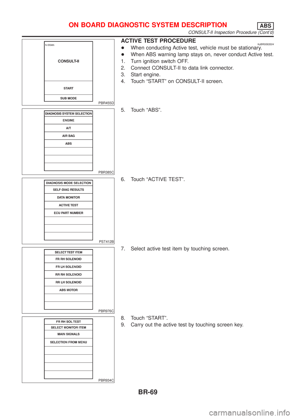
ACTIVE TEST PROCEDURENJBR0093S04+When conducting Active test, vehicle must be stationary.
+When ABS warning lamp stays on, never conduct Active test.
1. Turn ignition switch OFF.
2. Connect CONSULT-II to data link connector.
3. Start engine.
4. Touch ªSTARTº on CONSULT-II screen.
PBR385C
5. Touch ªABSº.
PST412B
6. Touch ªACTIVE TESTº.
PBR976C
7. Select active test item by touching screen.
PBR934C
8. Touch ªSTARTº.
9. Carry out the active test by touching screen key.
ON BOARD DIAGNOSTIC SYSTEM DESCRIPTIONABS
CONSULT-II Inspection Procedure (Cont'd)
BR-69
Page 586 of 2898
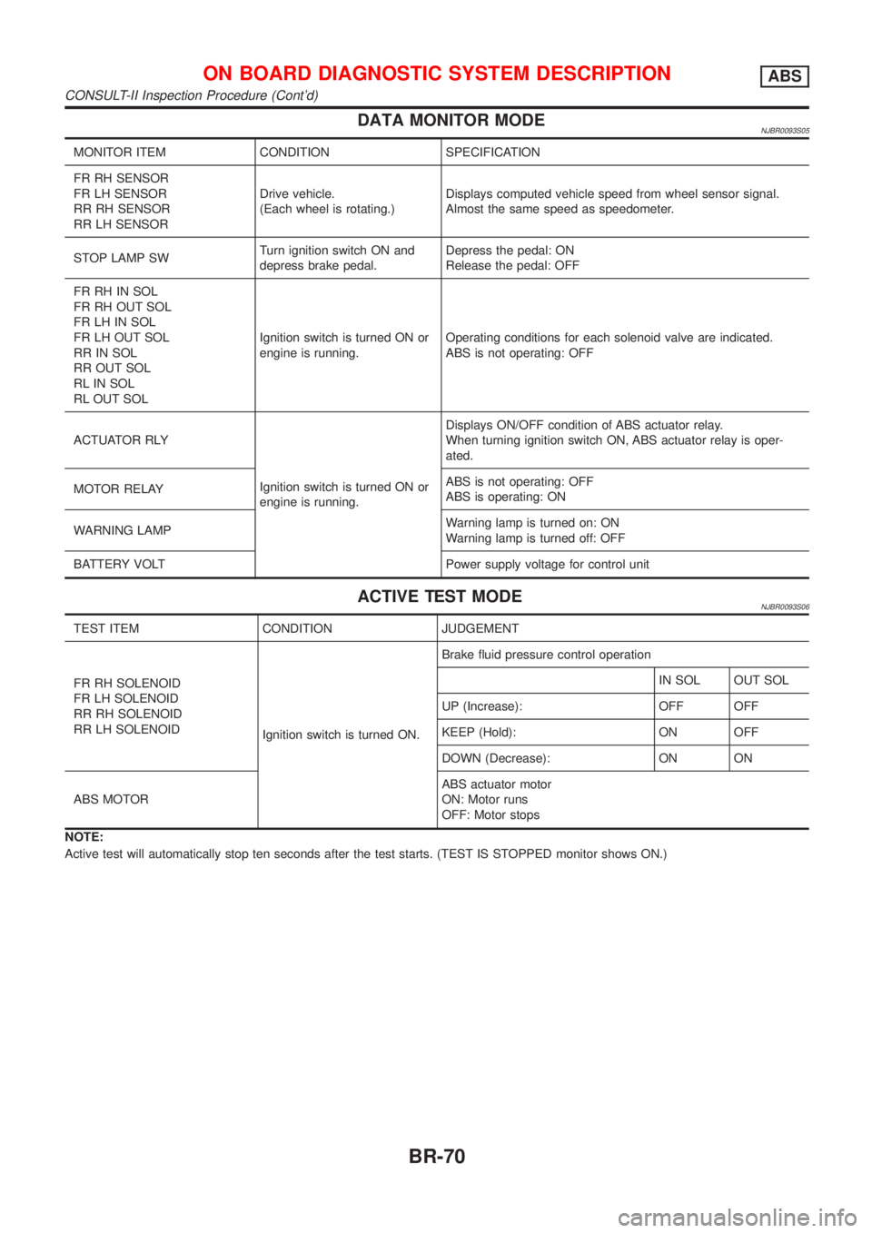
DATA MONITOR MODENJBR0093S05
MONITOR ITEM CONDITION SPECIFICATION
FR RH SENSOR
FR LH SENSOR
RR RH SENSOR
RR LH SENSORDrive vehicle.
(Each wheel is rotating.)Displays computed vehicle speed from wheel sensor signal.
Almost the same speed as speedometer.
STOP LAMP SWTurn ignition switch ON and
depress brake pedal.Depress the pedal: ON
Release the pedal: OFF
FR RH IN SOL
FR RH OUT SOL
FR LH IN SOL
FR LH OUT SOL
RR IN SOL
RR OUT SOL
RL IN SOL
RL OUT SOLIgnition switch is turned ON or
engine is running.Operating conditions for each solenoid valve are indicated.
ABS is not operating: OFF
ACTUATOR RLY
Ignition switch is turned ON or
engine is running.Displays ON/OFF condition of ABS actuator relay.
When turning ignition switch ON, ABS actuator relay is oper-
ated.
MOTOR RELAYABS is not operating: OFF
ABS is operating: ON
WARNING LAMPWarning lamp is turned on: ON
Warning lamp is turned off: OFF
BATTERY VOLT Power supply voltage for control unit
ACTIVE TEST MODENJBR0093S06
TEST ITEM CONDITION JUDGEMENT
FR RH SOLENOID
FR LH SOLENOID
RR RH SOLENOID
RR LH SOLENOID
Ignition switch is turned ON.Brake fluid pressure control operation
IN SOL OUT SOL
UP (Increase): OFF OFF
KEEP (Hold): ON OFF
DOWN (Decrease): ON ON
ABS MOTORABS actuator motor
ON: Motor runs
OFF: Motor stops
NOTE:
Active test will automatically stop ten seconds after the test starts. (TEST IS STOPPED monitor shows ON.)
ON BOARD DIAGNOSTIC SYSTEM DESCRIPTIONABS
CONSULT-II Inspection Procedure (Cont'd)
BR-70
Page 604 of 2898
6 CHECK ABS ACTUATOR AND ELECTRIC UNIT POWER SUPPLY CIRCUIT
Check continuity between battery and ABS actuator and electric unit connector terminal 15.
Does continuity exist?
Ye s©Check battery. Refer to BATTERY in EL section.
No©Check the following.
+Harness connector E1
+Harness for open or short between ABS actuator and electric unit and fuse
If NG, repair harness or connectors.
Control UnitNJBR0103DIAGNOSTIC PROCEDURENJBR0103S01(Malfunction code No. 71 for models with self-diagnosis func-
tion)
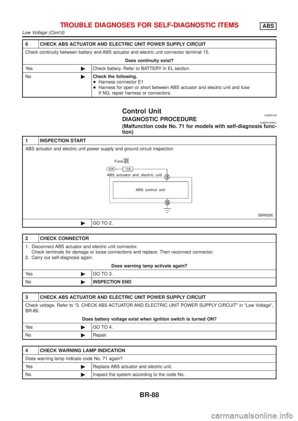
1 INSPECTION START
ABS actuator and electric unit power supply and ground circuit inspection
SBR626E
©GO TO 2.
2 CHECK CONNECTOR
1. Disconnect ABS actuator and electric unit connector.
Check terminals for damage or loose connections and replace. Then reconnect connector.
2. Carry out self-diagnosis again.
Does warning lamp activate again?
Ye s©GO TO 3.
No©INSPECTION END
3 CHECK ABS ACTUATOR AND ELECTRIC UNIT POWER SUPPLY CIRCUIT
Check voltage. Refer to ª3. CHECK ABS ACTUATOR AND ELECTRIC UNIT POWER SUPPLY CIRCUITº in ªLow Voltageº,
BR-86.
Does battery voltage exist when ignition switch is turned ON?
Ye s©GO TO 4.
No©Repair.
4 CHECK WARNING LAMP INDICATION
Does warning lamp indicate code No. 71 again?
Ye s©Replace ABS actuator and electric unit.
No©Inspect the system according to the code No.
TROUBLE DIAGNOSES FOR SELF-DIAGNOSTIC ITEMSABS
Low Voltage (Cont'd)
BR-88
Page 725 of 2898
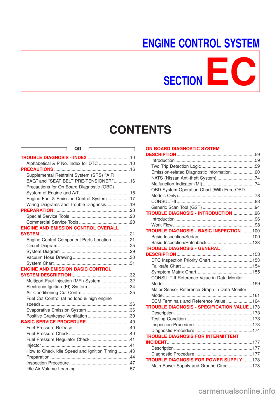
ENGINE CONTROL SYSTEM
SECTION
EC
CONTENTS
QG
TROUBLE DIAGNOSIS - INDEX..................................10
Alphabetical & P No. Index for DTC .........................10
PRECAUTIONS.............................................................16
Supplemental Restraint System (SRS)²AIR
BAG²and²SEAT BELT PRE-TENSIONER².............16
Precautions for On Board Diagnostic (OBD)
System of Engine and A/T.........................................16
Engine Fuel & Emission Control System ..................17
Wiring Diagrams and Trouble Diagnosis ...................19
PREPARATION.............................................................20
Special Service Tools ................................................20
Commercial Service Tools .........................................20
ENGINE AND EMISSION CONTROL OVERALL
SYSTEM.........................................................................21
Engine Control Component Parts Location ...............21
Circuit Diagram ..........................................................25
System Diagram ........................................................29
Vacuum Hose Drawing ..............................................30
System Chart .............................................................31
ENGINE AND EMISSION BASIC CONTROL
SYSTEM DESCRIPTION...............................................32
Multiport Fuel Injection (MFI) System .......................32
Electronic Ignition (EI) System ..................................34
Air Conditioning Cut Control ......................................35
Fuel Cut Control (at no load & high engine
speed) ........................................................................36
Evaporative Emission System ...................................36
Positive Crankcase Ventilation ..................................39
BASIC SERVICE PROCEDURE...................................40
Fuel Pressure Release ..............................................40
Fuel Pressure Check .................................................40
Fuel Pressure Regulator Check ................................41
Injector .......................................................................41
How to Check Idle Speed and Ignition Timing ..........43
Preparation ................................................................44
Inspection Procedure .................................................47
Idle Air Volume Learning ...........................................57ON BOARD DIAGNOSTIC SYSTEM
DESCRIPTION...............................................................59
Introduction ................................................................59
Two Trip Detection Logic ...........................................59
Emission-related Diagnostic Information ...................60
NATS (Nissan Anti-theft System) ..............................74
Malfunction Indicator (MI) ..........................................74
OBD System Operation Chart (With Euro-OBD
Models Only)..............................................................78
CONSULT-II ...............................................................83
Generic Scan Tool (GST) ..........................................94
TROUBLE DIAGNOSIS - INTRODUCTION..................96
Introduction ................................................................96
Work Flow ..................................................................98
TROUBLE DIAGNOSIS - BASIC INSPECTION.........100
Basic Inspection/Sedan ...........................................100
Basic Inspection/Hatchback.....................................128
TROUBLE DIAGNOSIS - GENERAL
DESCRIPTION.............................................................153
DTC Inspection Priority Chart..................................153
Fail-safe Chart .........................................................154
Symptom Matrix Chart .............................................155
CONSULT-II Reference Value in Data Monitor
Mode ........................................................................159
Major Sensor Reference Graph in Data Monitor
Mode ........................................................................161
ECM Terminals and Reference Value .....................164
TROUBLE DIAGNOSIS - SPECIFICATION VALUE..173
Description ...............................................................173
Testing Condition .....................................................173
Inspection Procedure ...............................................173
Diagnostic Procedure ..............................................174
TROUBLE DIAGNOSIS FOR INTERMITTENT
INCIDENT.....................................................................177
Description ...............................................................177
Diagnostic Procedure ..............................................177
TROUBLE DIAGNOSIS FOR POWER SUPPLY........178
Main Power Supply and Ground Circuit ..................178
Page 730 of 2898
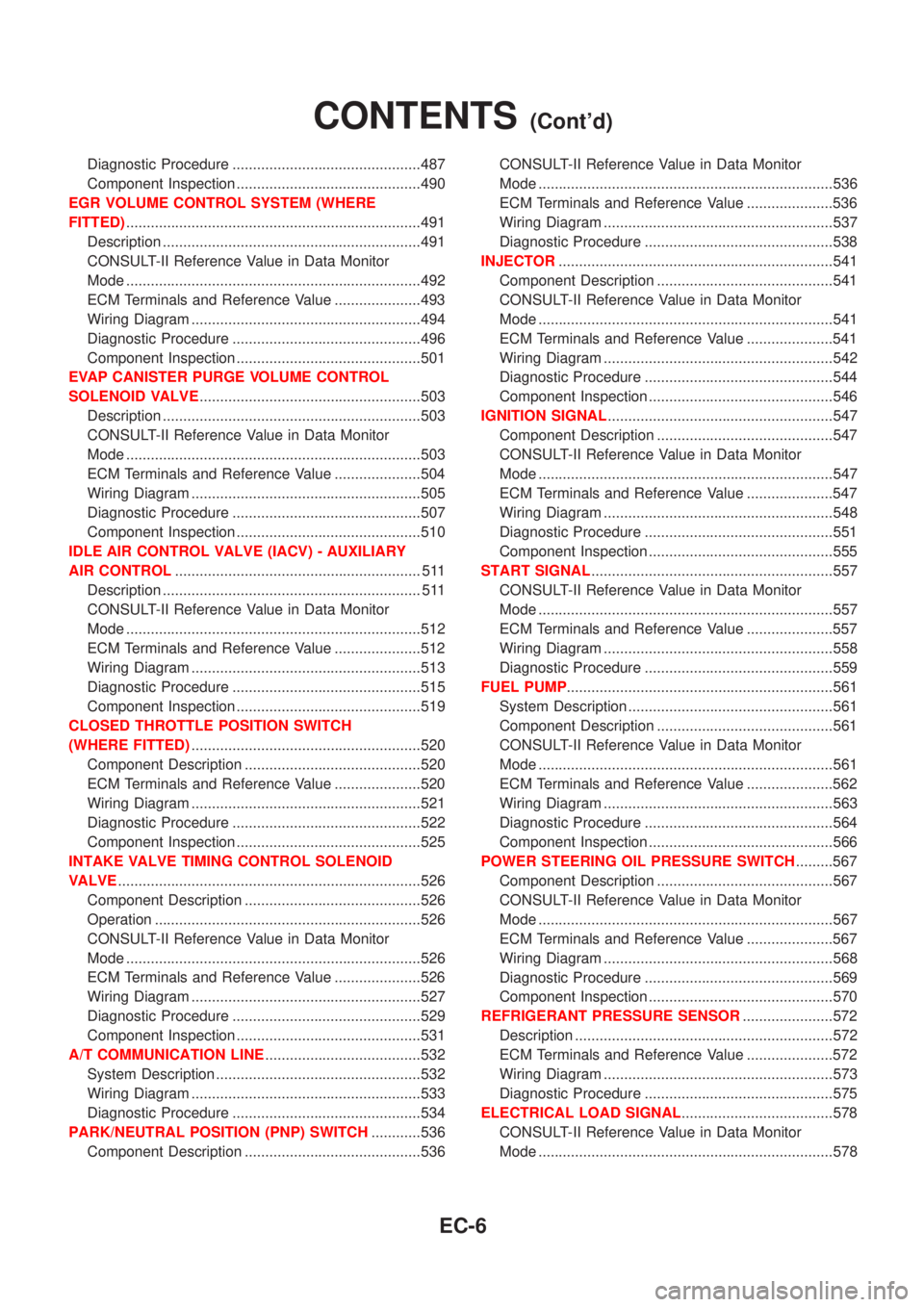
Diagnostic Procedure ..............................................487
Component Inspection .............................................490
EGR VOLUME CONTROL SYSTEM (WHERE
FITTED)........................................................................491
Description ...............................................................491
CONSULT-II Reference Value in Data Monitor
Mode ........................................................................492
ECM Terminals and Reference Value .....................493
Wiring Diagram ........................................................494
Diagnostic Procedure ..............................................496
Component Inspection .............................................501
EVAP CANISTER PURGE VOLUME CONTROL
SOLENOID VALVE......................................................503
Description ...............................................................503
CONSULT-II Reference Value in Data Monitor
Mode ........................................................................503
ECM Terminals and Reference Value .....................504
Wiring Diagram ........................................................505
Diagnostic Procedure ..............................................507
Component Inspection .............................................510
IDLE AIR CONTROL VALVE (IACV) - AUXILIARY
AIR CONTROL............................................................ 511
Description ............................................................... 511
CONSULT-II Reference Value in Data Monitor
Mode ........................................................................512
ECM Terminals and Reference Value .....................512
Wiring Diagram ........................................................513
Diagnostic Procedure ..............................................515
Component Inspection .............................................519
CLOSED THROTTLE POSITION SWITCH
(WHERE FITTED)........................................................520
Component Description ...........................................520
ECM Terminals and Reference Value .....................520
Wiring Diagram ........................................................521
Diagnostic Procedure ..............................................522
Component Inspection .............................................525
INTAKE VALVE TIMING CONTROL SOLENOID
VALVE..........................................................................526
Component Description ...........................................526
Operation .................................................................526
CONSULT-II Reference Value in Data Monitor
Mode ........................................................................526
ECM Terminals and Reference Value .....................526
Wiring Diagram ........................................................527
Diagnostic Procedure ..............................................529
Component Inspection .............................................531
A/T COMMUNICATION LINE......................................532
System Description ..................................................532
Wiring Diagram ........................................................533
Diagnostic Procedure ..............................................534
PARK/NEUTRAL POSITION (PNP) SWITCH............536
Component Description ...........................................536CONSULT-II Reference Value in Data Monitor
Mode ........................................................................536
ECM Terminals and Reference Value .....................536
Wiring Diagram ........................................................537
Diagnostic Procedure ..............................................538
INJECTOR...................................................................541
Component Description ...........................................541
CONSULT-II Reference Value in Data Monitor
Mode ........................................................................541
ECM Terminals and Reference Value .....................541
Wiring Diagram ........................................................542
Diagnostic Procedure ..............................................544
Component Inspection .............................................546
IGNITION SIGNAL.......................................................547
Component Description ...........................................547
CONSULT-II Reference Value in Data Monitor
Mode ........................................................................547
ECM Terminals and Reference Value .....................547
Wiring Diagram ........................................................548
Diagnostic Procedure ..............................................551
Component Inspection .............................................555
START SIGNAL...........................................................557
CONSULT-II Reference Value in Data Monitor
Mode ........................................................................557
ECM Terminals and Reference Value .....................557
Wiring Diagram ........................................................558
Diagnostic Procedure ..............................................559
FUEL PUMP.................................................................561
System Description ..................................................561
Component Description ...........................................561
CONSULT-II Reference Value in Data Monitor
Mode ........................................................................561
ECM Terminals and Reference Value .....................562
Wiring Diagram ........................................................563
Diagnostic Procedure ..............................................564
Component Inspection .............................................566
POWER STEERING OIL PRESSURE SWITCH.........567
Component Description ...........................................567
CONSULT-II Reference Value in Data Monitor
Mode ........................................................................567
ECM Terminals and Reference Value .....................567
Wiring Diagram ........................................................568
Diagnostic Procedure ..............................................569
Component Inspection .............................................570
REFRIGERANT PRESSURE SENSOR......................572
Description ...............................................................572
ECM Terminals and Reference Value .....................572
Wiring Diagram ........................................................573
Diagnostic Procedure ..............................................575
ELECTRICAL LOAD SIGNAL.....................................578
CONSULT-II Reference Value in Data Monitor
Mode ........................................................................578
CONTENTS(Cont'd)
EC-6
Page 731 of 2898

ECM Terminals and Reference Value .....................578
Wiring Diagram ........................................................579
Diagnostic Procedure - Load Signal - .....................583
Diagnostic Procedure - Heater Control Panel
(Fan Switch) - ..........................................................589
Component Inspection .............................................590
MI & DATA LINK CONNECTORS..............................591
Wiring Diagram ........................................................591
SERVICE DATA AND SPECIFICATIONS (SDS).......593
Fuel Pressure Regulator..........................................593
Idle Speed and Ignition Timing ................................593
Mass Air Flow Sensor..............................................593
Intake Air Temperature Sensor ................................593
Engine Coolant Temperature Sensor ......................593
Throttle Position Sensor ..........................................593
Heated Oxygen Sensor 1 Heater (Front) ................593
Heated Oxygen Sensor 2 Heater (Rear).................593
Fuel Tank Temperature Sensor (Where Fitted) .......594
EGR Volume Control Valve (Where Fitted) .............594
EGR Temperature Sensor (Where Fitted) ...............594
EVAP Canister Purge Volume Control Valve ..........594
IACV-AAC Valve ......................................................594
Injector .....................................................................594
Ignition Coil with Power Transistor ..........................594
Condenser ...............................................................594
Fuel Pump ...............................................................594
Crankshaft Position Sensor (POS) ..........................595
Camshaft Position Sensor (PHASE) .......................595
YD
TROUBLE DIAGNOSIS - INDEX................................596
Alphabetical & P No. Index for DTC .......................596
PRECAUTIONS...........................................................598
Supplemental Restraint System (SRS)²AIR
BAG²and²SEAT BELT PRE-TENSIONER²...........598
Engine Fuel & Emission Control System ................599
Precautions ..............................................................600
Wiring Diagrams and Trouble Diagnosis .................601
PREPARATION...........................................................602
Special Service Tools ..............................................602
ENGINE AND EMISSION CONTROL OVERALL
SYSTEM.......................................................................603
Engine Control Component Parts Location .............603
Circuit Diagram ........................................................606
System Diagram ......................................................608
System Chart ...........................................................609
ENGINE AND EMISSION BASIC CONTROL
SYSTEM DESCRIPTION.............................................610
Fuel Injection Control System .................................610
Fuel Injection Timing Control System...................... 611
Air Conditioning Cut Control ....................................612Fuel Cut Control (at no load & high engine
speed) ......................................................................612
Crankcase Ventilation System .................................613
BASIC SERVICE PROCEDURE.................................614
Injection Tube and Injection Nozzle ........................614
Electronic Control Fuel Injection Pump ...................618
Fuel Filter .................................................................625
ON BOARD DIAGNOSTIC SYSTEM
DESCRIPTION.............................................................627
DTC and MI Detection Logic ...................................627
Diagnostic Trouble Code (DTC) ..............................627
Malfunction Indicator (MI) ........................................628
CONSULT-II .............................................................632
TROUBLE DIAGNOSIS - INTRODUCTION................637
Introduction ..............................................................637
Work Flow ................................................................639
TROUBLE DIAGNOSIS - BASIC INSPECTION.........641
Basic Inspection.......................................................641
TROUBLE DIAGNOSIS - GENERAL
DESCRIPTION.............................................................646
Symptom Matrix Chart .............................................646
CONSULT-II Reference Value in Data Monitor
Mode ........................................................................656
Major Sensor Reference Graph in Data Monitor
Mode ........................................................................658
ECM Terminals and Reference Value .....................659
TROUBLE DIAGNOSIS FOR INTERMITTENT
INCIDENT.....................................................................665
Description ...............................................................665
Diagnostic Procedure ..............................................665
TROUBLE DIAGNOSIS FOR POWER SUPPLY........666
Main Power Supply and Ground Circuit ..................666
DTC P0100 MASS AIR FLOW SEN...........................673
Component Description ...........................................673
CONSULT-II Reference Value in Data Monitor
Mode ........................................................................673
ECM Terminals and Reference Value .....................673
On Board Diagnosis Logic.......................................673
DTC Confirmation Procedure ..................................673
Wiring Diagram ........................................................675
Diagnostic Procedure ..............................................677
DTC P0115 COOLANT TEMP SEN............................680
Description ...............................................................680
On Board Diagnosis Logic.......................................680
DTC Confirmation Procedure ..................................680
Wiring Diagram ........................................................682
Diagnostic Procedure ..............................................683
DTC P0120 ACCEL POS SENSOR............................685
Description ...............................................................685
CONSULT-II Reference Value in Data Monitor
Mode ........................................................................685
ECM Terminals and Reference Value .....................685
CONTENTS(Cont'd)
EC-7
Page 740 of 2898

Supplemental Restraint System (SRS) ªAIR
BAGº and ªSEAT BELT PRE-TENSIONERº
NJEC0002The Supplemental Restraint System such as ªAIR BAGº and ªSEAT BELT PRE-TENSIONERº used along with
a seat belt, helps to reduce the risk or severity of injury to the driver and front passenger for certain types of
collision. The SRS system composition which is available to NISSAN MODEL N16 is as follows (The compo-
sition varies according to the destination and optional equipment.):
+For a frontal collision
The Supplemental Restraint System consists of driver air bag module (located in the center of the steer-
ing wheel), front passenger air bag module (located on the instrument panel on passenger side), front seat
belt pre-tensioners, a diagnoses sensor unit, warning lamp, wiring harness and spiral cable.
+For a side collision
The Supplemental Restraint System consists of front side air bag module (located in the outer side of front
seat), side air bag (satellite) sensor, diagnoses sensor unit (one of components of air bags for a frontal
collision), wiring harness, warning lamp (one of components of air bags for a frontal collision).
Information necessary to service the system safely is included in theRS sectionof this Service Manual.
WARNING:
+To avoid rendering the SRS inoperative, which could increase the risk of personal injury or death
in the event of a collision which would result in air bag inflation, all maintenance should be per-
formed by an authorized NISSAN dealer.
+Improper maintenance, including incorrect removal and installation of the SRS, can lead to per-
sonal injury caused by unintentional activation of the system. For removal of Spiral Cable and Air
Bag Module, see the RS section.
+Do not use electrical test equipment on any circuit related to the SRS unless instructed to in this
Service Manual. SRS wiring harness can be identified by yellow harness connector.
Precautions for On Board Diagnostic (OBD)
System of Engine and A/T
NJEC0003The ECM has an on board diagnostic system. It will light up the malfunction indicator (MI) to warn the driver
of a malfunction causing emission deterioration.
CAUTION:
+Be sure to turn the ignition switch ªOFFº and disconnect the negative battery terminal before any
repair or inspection work. The open/short circuit of related switches, sensors, solenoid valves, etc.
will cause the MI to light up.
+Be sure to connect and lock the connectors securely after work. A loose (unlocked) connector will
cause the MI to light up due to the open circuit. (Be sure the connector is free from water, grease,
dirt, bent terminals, etc.)
+Certain systems and components, especially those related to OBD, may use a new style slide-
locking type harness connector.
For description and how to disconnect, refer to EL section, ªDescriptionº, ªHARNESS CONNEC-
TORº.
+Be sure to route and secure the harnesses properly after work. The interference of the harness with
a bracket, etc. may cause the MI to light up due to the short circuit.
+Be sure to connect rubber tubes properly after work. A misconnected or disconnected rubber tube
may cause the MI to light up due to the malfunction of fuel injection system, etc.
+Be sure to erase the unnecessary malfunction information (repairs completed) from the ECM and
TCM (Transmission Control Module) before returning the vehicle to the customer.
PRECAUTIONSQG
Supplemental Restraint System (SRS) ªAIR BAGº and ªSEAT BELT PRE-TENSIONERº
EC-16