2001 NISSAN ALMERA Ignition system
[x] Cancel search: Ignition systemPage 773 of 2898
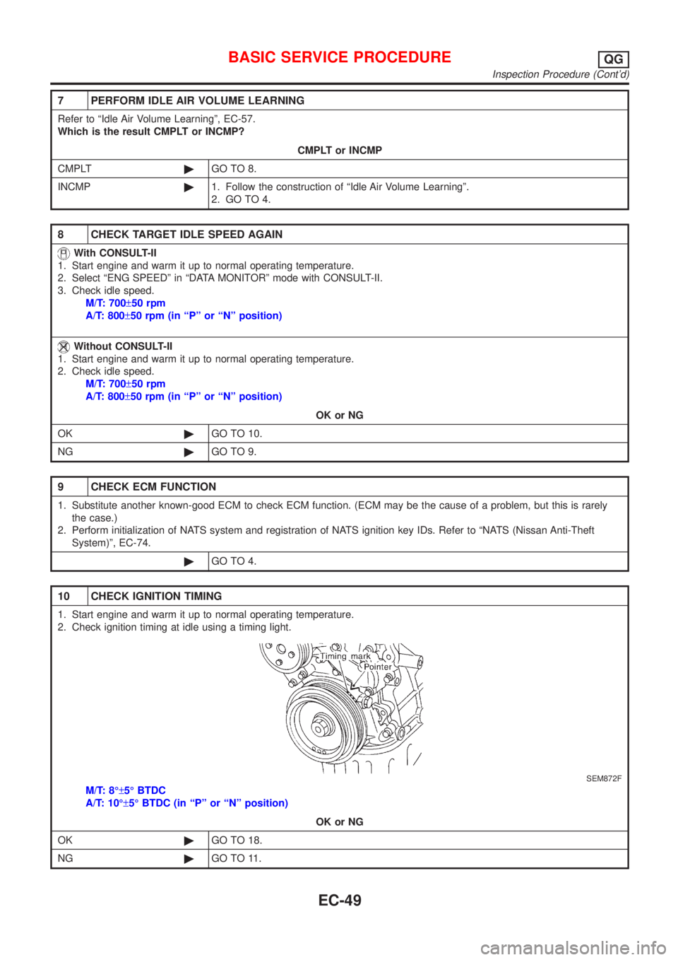
7 PERFORM IDLE AIR VOLUME LEARNING
Refer to ªIdle Air Volume Learningº, EC-57.
Which is the result CMPLT or INCMP?
CMPLT or INCMP
CMPLT©GO TO 8.
INCMP©1. Follow the construction of ªIdle Air Volume Learningº.
2. GO TO 4.
8 CHECK TARGET IDLE SPEED AGAIN
With CONSULT-II
1. Start engine and warm it up to normal operating temperature.
2. Select ªENG SPEEDº in ªDATA MONITORº mode with CONSULT-II.
3. Check idle speed.
M/T: 700±50 rpm
A/T: 800±50 rpm (in ªPº or ªNº position)
Without CONSULT-II
1. Start engine and warm it up to normal operating temperature.
2. Check idle speed.
M/T: 700±50 rpm
A/T: 800±50 rpm (in ªPº or ªNº position)
OK or NG
OK©GO TO 10.
NG©GO TO 9.
9 CHECK ECM FUNCTION
1. Substitute another known-good ECM to check ECM function. (ECM may be the cause of a problem, but this is rarely
the case.)
2. Perform initialization of NATS system and registration of NATS ignition key IDs. Refer to ªNATS (Nissan Anti-Theft
System)º, EC-74.
©GO TO 4.
10 CHECK IGNITION TIMING
1. Start engine and warm it up to normal operating temperature.
2. Check ignition timing at idle using a timing light.
SEM872F
M/T: 8ɱ5É BTDC
A/T: 10ɱ5É BTDC (in ªPº or ªNº position)
OK or NG
OK©GO TO 18.
NG©GO TO 11.
BASIC SERVICE PROCEDUREQG
Inspection Procedure (Cont'd)
EC-49
Page 775 of 2898
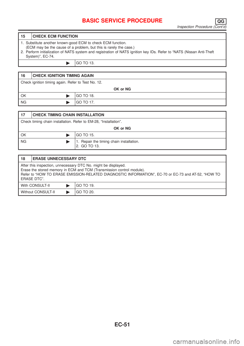
15 CHECK ECM FUNCTION
1. Substitute another known-good ECM to check ECM function.
(ECM may be the cause of a problem, but this is rarely the case.)
2. Perform initialization of NATS system and registration of NATS ignition key IDs. Refer to ªNATS (Nissan Anti-Theft
System)º, EC-74.
©GO TO 13.
16 CHECK IGNITION TIMING AGAIN
Check ignition timing again. Refer to Test No. 12.
OK or NG
OK©GO TO 18.
NG©GO TO 17.
17 CHECK TIMING CHAIN INSTALLATION
Check timing chain installation. Refer to EM-28, ªInstallationº.
OK or NG
OK©GO TO 15.
NG©1. Repair the timing chain installation.
2. GO TO 13.
18 ERASE UNNECESSARY DTC
After this inspection, unnecessary DTC No. might be displayed.
Erase the stored memory in ECM and TCM (Transmission control module).
Refer to ªHOW TO ERASE EMISSION-RELATED DIAGNOSTIC INFORMATIONº, EC-70 or EC-73 and AT-52, ªHOW TO
ERASE DTCº.
With CONSULT-II©GO TO 19.
Without CONSULT-II©GO TO 20.
BASIC SERVICE PROCEDUREQG
Inspection Procedure (Cont'd)
EC-51
Page 781 of 2898

SEF217Z
SEF454Y
SEF455Y
Idle Air Volume LearningNJEC0562DESCRIPTIONNJEC0562S01ªIdle Air Volume Learningº is an operation to learn the idle air vol-
ume that keeps each engine within the specific range. It must be
performed under any of the following conditions:
+Each time IACV-AAC valve, throttle body or ECM is replaced.
+Idle speed or ignition timing is out of specification.
PRE-CONDITIONINGNJEC0562S02Before performing ªIdle Air Volume Learningº, make sure that all of
the following conditions are satisfied.
Learning will be cancelled if any of the following conditions are
missed for even a moment.
+Battery voltage: More than 12.9V (At idle)
+Engine coolant temperature: 70 - 99ÉC (158 - 210ÉF)
+PNP switch: ON
+Electric load switch: OFF
(Air conditioner, headlamp, rear window defogger)
On vehicles equipped with daytime light systems, set lighting
switch to the 1st position to light only small lamps.
+Cooling fan motor: Not operating
+Steering wheel: Neutral (Straight-ahead position)
+Vehicle speed: Stopped
+Transmission: Warmed-up
For A/T models with CONSULT-II, drive vehicle until ªFLUID
TEMP SEº in ªDATA MONITORº mode of ªA/Tº system indi-
cates less than 0.9V.
For A/T models without CONSULT-II and M/T models, drive
vehicle for 10 minutes.
OPERATION PROCEDURENJEC0562S03With CONSULT-IINJEC0562S03011. Turn ignition switch ªONº and wait at least 1 second.
2. Turn ignition switch ªOFFº and wait at least 10 seconds.
3. Start engine and warm it up to normal operating temperature.
4. Check that all items listed under the topic ªPRE-CONDITION-
INGº (previously mentioned) are in good order.
5. Turn ignition switch ªOFFº and wait at least 9 seconds.
6. Start the engine and let it idle for at least 28 seconds.
7. Select ªIDLE AIR VOL LEARNº in ªWORK SUPPORTº mode.
8. Touch ªSTARTº and wait 20 seconds.
9. Make sure that ªCMPLTº is displayed on CONSULT-II screen.
If ªINCMPº is displayed, ªIdle Air Volume Learningº will not be
carried out successfully. In this case, find the cause of the
problem by referring to the NOTE below.
10. Rev up the engine two or three times. Make sure that idle
speed and ignition timing are within specifications.
ITEM SPECIFICATION
Idle speed M/T: 700±50 rpm
A/T: 800±50 rpm (in ªPº or ªNº position)
Ignition timing M/T: 8±5É BTDC
A/T: 10±5É BTDC (in ªPº or ªNº position)
Without CONSULT-IINJEC0562S03021. Turn ignition switch ªONº and wait at least 1 second.
BASIC SERVICE PROCEDUREQG
Inspection Procedure (Cont'd)
EC-57
Page 782 of 2898

JEF091Y
2. Turn ignition switch ªOFFº and wait at least 10 seconds.
3. Start engine and warm it up to normal operating temperature.
4. Check that all items listed under the topic ªPRE-CONDITION-
INGº (previously mentioned) are in good order.
5. Turn ignition switch ªOFFº and wait at least 9 seconds.
6. Start the engine and let it idle for at least 28 seconds.
7. Disconnect throttle position sensor harness connector (brown),
then reconnect it within 5 seconds.
8. Wait 20 seconds.
9. Make sure that idle speed is within specifications. If not, the
result will be incomplete. In this case, find the cause of the
problem by referring to the NOTE below.
10. Rev up the engine two or three times. Make sure that idle
speed and ignition timing are within specifications.
ITEM SPECIFICATION
Idle speed M/T: 700±50 rpm
A/T: 800±50 rpm (in ªPº or ªNº position)
Ignition timing M/T: 8±5É BTDC
A/T: 10±5É BTDC (in ªPº or ªNº position)
NOTE:
If idle air volume learning cannot be performed successfully,
proceed as follows:
1)Check that throttle valve is fully closed.
2)Check PCV valve operation.
3)Check that downstream of throttle valve is free from air
leakage.
4)Adjust closed throttle position switch and reset memory.
(Refer to Basic Inspection, EC-100.)
5)When the above three items check out OK, engine com-
ponent parts and their installation condition are question-
able. Check and eliminate the cause of the problem.
It is useful to perform ªTROUBLE DIAGNOSIS Ð SPECIFI-
CATION VALVEº, EC-173.
6)If any of the following conditions occur after the engine
has started, eliminate the cause of the problem and per-
form ªIdle air volume learningº all over again:
+Engine stalls.
+Erroneous idle.
+Blown fuses related to the IACV-AAC valve system.
BASIC SERVICE PROCEDUREQG
Idle Air Volume Learning (Cont'd)
EC-58
Page 787 of 2898
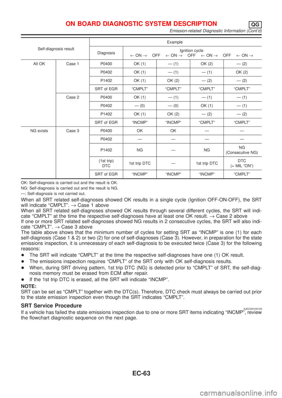
Self-diagnosis resultExample
DiagnosisIgnition cycle
¬ON®OFF¬ON®OFF¬ON®OFF¬ON®
All OK Case 1 P0400 OK (1) Ð (1) OK (2) Ð (2)
P0402 OK (1) Ð (1) Ð (1) OK (2)
P1402 OK (1) OK (2) Ð (2) Ð (2)
SRT of EGR ªCMPLTº ªCMPLTº ªCMPLTº ªCMPLTº
Case 2 P0400 OK (1) Ð (1) Ð (1) Ð (1)
P0402 Ð (0) Ð (0) OK (1) Ð (1)
P1402 OK (1) OK (2) Ð (2) Ð (2)
SRT of EGR ªINCMPº ªINCMPº ªCMPLTº ªCMPLTº
NG exists Case 3 P0400 OK OK Ð Ð
P0402 Ð Ð Ð Ð
P1402 NG Ð NGNG
(Consecutive NG)
(1st trip)
DTC1st trip DTC Ð 1st trip DTCDTC
(= MIL ªONº)
SRT of EGR ªINCMPº ªINCMPº ªINCMPº ªCMPLTº
OK: Self-diagnosis is carried out and the result is OK.
NG: Self-diagnosis is carried out and the result is NG.
Ð: Self-diagnosis is not carried out.
When all SRT related self-diagnoses showed OK results in a single cycle (Ignition OFF-ON-OFF), the SRT
will indicate ªCMPLTº.®Case 1 above
When all SRT related self-diagnoses showed OK results through several different cycles, the SRT will indi-
cate ªCMPLTº at the time the respective self-diagnoses have at least one OK result.®Case 2 above
If one or more SRT related self-diagnoses showed NG results in 2 consecutive cycles, the SRT will also indi-
cate ªCMPLTº.®Case 3 above
The table above shows that the minimum number of cycles for setting SRT as ªINCMPº is one (1) for each
self-diagnosis (Case1&2)ortwo(2)foroneofself-diagnoses (Case 3). However, in preparation for the state
emissions inspection, it is unnecessary of each self-diagnosis to be executed twice (Case 3) for the following
reasons:
+The SRT will indicate ªCMPLTº at the time the respective self-diagnoses have one (1) OK result.
+The emissions inspection requires ªCMPLTº of the SRT only with OK self-diagnosis results.
+When, during SRT driving pattern, 1st trip DTC (NG) is detected prior to ªCMPLTº of SRT, the self-diag-
nosis memory must be erased from ECM after repair.
+If the 1st trip DTC is erased, all the SRT will indicate ªINCMPº.
NOTE:
SRT can be set as ªCMPLTº together with the DTC(s). Therefore, DTC check must always be carried out prior
to the state emission inspection even though the SRT indicates ªCMPLTº.
SRT Service ProcedureNJEC0031S0109If a vehicle has failed the state emissions inspection due to one or more SRT items indicating ªINCMPº, review
the flowchart diagnostic sequence on the next page.
ON BOARD DIAGNOSTIC SYSTEM DESCRIPTIONQG
Emission-related Diagnostic Information (Cont'd)
EC-63
Page 794 of 2898
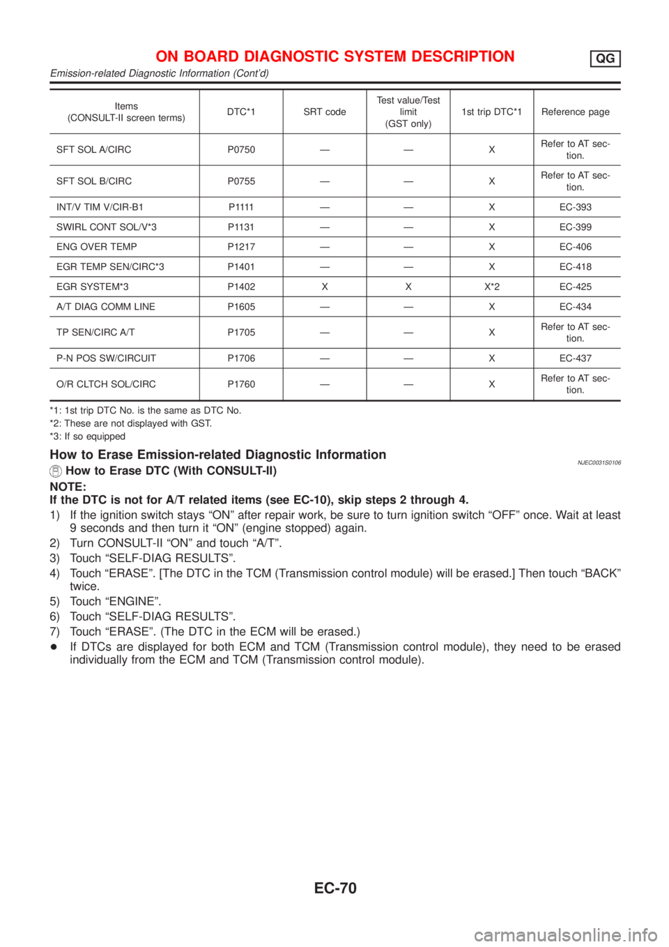
Items
(CONSULT-II screen terms)DTC*1 SRT codeTest value/Test
limit
(GST only)1st trip DTC*1 Reference page
SFT SOL A/CIRC P0750 Ð Ð XRefer to AT sec-
tion.
SFT SOL B/CIRC P0755 Ð Ð XRefer to AT sec-
tion.
INT/V TIM V/CIR-B1 P1111 Ð Ð XEC-393
SWIRL CONT SOL/V*3 P1131 Ð Ð X EC-399
ENG OVER TEMP P1217 Ð Ð X EC-406
EGR TEMP SEN/CIRC*3 P1401 Ð Ð X EC-418
EGR SYSTEM*3 P1402 X X X*2 EC-425
A/T DIAG COMM LINE P1605 Ð Ð X EC-434
TP SEN/CIRC A/T P1705 Ð Ð XRefer to AT sec-
tion.
P-N POS SW/CIRCUIT P1706 Ð Ð X EC-437
O/R CLTCH SOL/CIRC P1760 Ð Ð XRefer to AT sec-
tion.
*1: 1st trip DTC No. is the same as DTC No.
*2: These are not displayed with GST.
*3: If so equipped
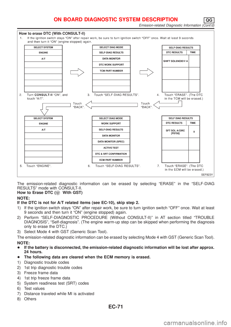
How to Erase Emission-related Diagnostic InformationNJEC0031S0106How to Erase DTC (With CONSULT-II)
NOTE:
If the DTC is not for A/T related items (see EC-10), skip steps 2 through 4.
1) If the ignition switch stays ªONº after repair work, be sure to turn ignition switch ªOFFº once. Wait at least
9 seconds and then turn it ªONº (engine stopped) again.
2) Turn CONSULT-II ªONº and touch ªA/Tº.
3) Touch ªSELF-DIAG RESULTSº.
4) Touch ªERASEº. [The DTC in the TCM (Transmission control module) will be erased.] Then touch ªBACKº
twice.
5) Touch ªENGINEº.
6) Touch ªSELF-DIAG RESULTSº.
7) Touch ªERASEº. (The DTC in the ECM will be erased.)
+If DTCs are displayed for both ECM and TCM (Transmission control module), they need to be erased
individually from the ECM and TCM (Transmission control module).
ON BOARD DIAGNOSTIC SYSTEM DESCRIPTIONQG
Emission-related Diagnostic Information (Cont'd)
EC-70
Page 795 of 2898
SEF823Y
The emission-related diagnostic information can be erased by selecting ªERASEº in the ªSELF-DIAG
RESULTSº mode with CONSULT-II.
How to Erase DTC (
With GST)
NOTE:
If the DTC is not for A/T related items (see EC-10), skip step 2.
1) If the ignition switch stays ªONº after repair work, be sure to turn ignition switch ªOFFº once. Wait at least
9 seconds and then turn it ªONº (engine stopped) again.
2) Perform ªSELF-DIAGNOSTIC PROCEDURE (Without CONSULT-II)º in AT section titled ªTROUBLE
DIAGNOSISº, ªSelf-diagnosisº. (The engine warm-up step can be skipped when performing the diagnosis
only to erase the DTC.)
3) Select Mode 4 with GST (Generic Scan Tool).
The emission-related diagnostic information can be erased by selecting Mode 4 with GST (Generic Scan Tool).
NOTE:
+If the battery is disconnected, the emission-related diagnostic information will be lost after approx.
24 hours.
+The following data are cleared when the ECM memory is erased.
1) Diagnostic trouble codes
2) 1st trip diagnostic trouble codes
3) Freeze frame data
4) 1st trip freeze frame data
5) System readiness test (SRT) codes
6) Test values
7) Distance traveled while MI is activated
8) Others
ON BOARD DIAGNOSTIC SYSTEM DESCRIPTIONQG
Emission-related Diagnostic Information (Cont'd)
EC-71
Page 797 of 2898
Only one set of freeze frame data (either 1st trip freeze frame data or freeze frame data) can be stored in the
ECM. 1st trip freeze frame data is stored in the ECM memory along with the 1st trip DTC. There is no prior-
ity for 1st trip freeze frame data and it is updated each time a different 1st trip DTC is detected. However, once
freeze frame data is stored in the ECM memory, 1st trip freeze frame data is no longer stored. Remember,
only one set of freeze frame data can be stored in the ECM.
If freeze frame data is stored in the ECM memory and another freeze frame data occurs later, the first (origi-
nal) freeze frame data remains unchanged in the ECM memory.
Both 1st trip freeze frame data and freeze frame data (along with the DTCs) are cleared when the ECM
memory is erased. Procedures for clearing the ECM memory are described in ªHow to Erase Emission-related
Diagnostic Informationº, EC-73.
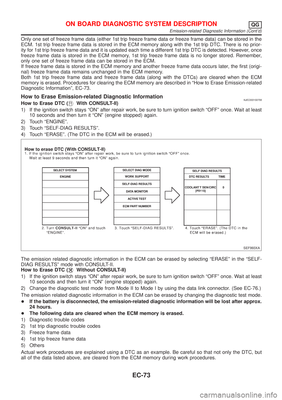
How to Erase Emission-related Diagnostic InformationNJEC0031S0706How to Erase DTC (With CONSULT-II)
1) If the ignition switch stays ªONº after repair work, be sure to turn ignition switch ªOFFº once. Wait at least
10 seconds and then turn it ªONº (engine stopped) again.
2) Touch ªENGINEº.
3) Touch ªSELF-DIAG RESULTSº.
4) Touch ªERASEº. (The DTC in the ECM will be erased.)
SEF993XA
The emission related diagnostic information in the ECM can be erased by selecting ªERASEº in the ªSELF-
DIAG RESULTSº mode with CONSULT-II.
How to Erase DTC (
Without CONSULT-II)
1) If the ignition switch stays ªONº after repair work, be sure to turn ignition switch ªOFFº once. Wait at least
10 seconds and then turn it ªONº (engine stopped) again.
2) Change the diagnostic test mode from Mode II to Mode I by using the data link connector. (See EC-76.)
The emission related diagnostic information in the ECM can be erased by changing the diagnostic test mode.
+If the battery is disconnected, the emission-related diagnostic information will be lost after approx.
24 hours.
+The following data are cleared when the ECM memory is erased.
1) Diagnostic trouble codes
2) 1st trip diagnostic trouble codes
3) Freeze frame data
4) 1st trip freeze frame data
5) Others
Actual work procedures are explained using a DTC as an example. Be careful so that not only the DTC, but
all of the data listed above, are cleared from the ECM memory during work procedures.
ON BOARD DIAGNOSTIC SYSTEM DESCRIPTIONQG
Emission-related Diagnostic Information (Cont'd)
EC-73