2001 NISSAN ALMERA turn signal
[x] Cancel search: turn signalPage 1536 of 2898
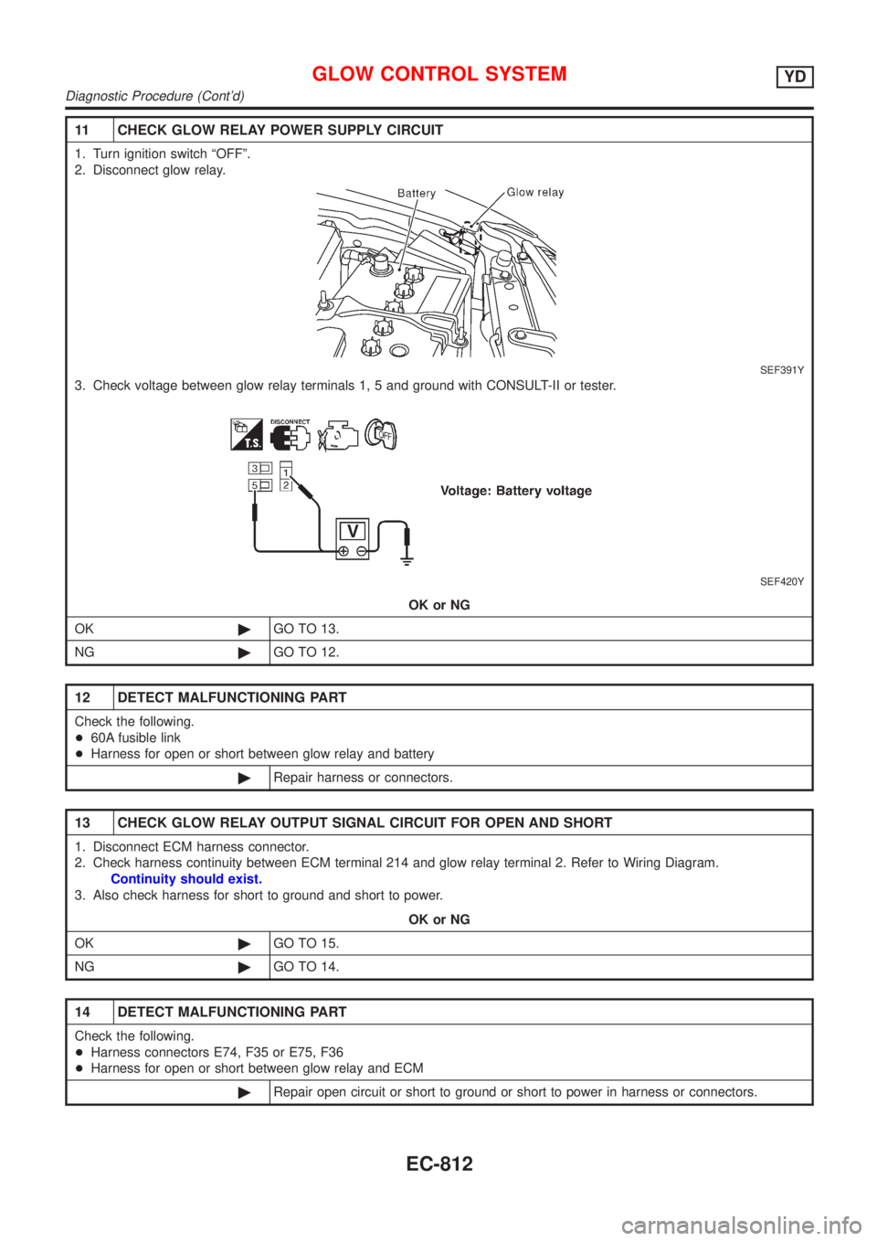
11 CHECK GLOW RELAY POWER SUPPLY CIRCUIT
1. Turn ignition switch ªOFFº.
2. Disconnect glow relay.
SEF391Y
3. Check voltage between glow relay terminals 1, 5 and ground with CONSULT-II or tester.
SEF420Y
OK or NG
OK©GO TO 13.
NG©GO TO 12.
12 DETECT MALFUNCTIONING PART
Check the following.
+60A fusible link
+Harness for open or short between glow relay and battery
©Repair harness or connectors.
13 CHECK GLOW RELAY OUTPUT SIGNAL CIRCUIT FOR OPEN AND SHORT
1. Disconnect ECM harness connector.
2. Check harness continuity between ECM terminal 214 and glow relay terminal 2. Refer to Wiring Diagram.
Continuity should exist.
3. Also check harness for short to ground and short to power.
OK or NG
OK©GO TO 15.
NG©GO TO 14.
14 DETECT MALFUNCTIONING PART
Check the following.
+Harness connectors E74, F35 or E75, F36
+Harness for open or short between glow relay and ECM
©Repair open circuit or short to ground or short to power in harness or connectors.
GLOW CONTROL SYSTEMYD
Diagnostic Procedure (Cont'd)
EC-812
Page 1539 of 2898
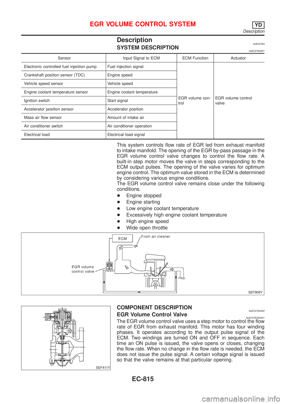
DescriptionNJEC0764SYSTEM DESCRIPTIONNJEC0764S01
Sensor Input Signal to ECM ECM Function Actuator
Electronic controlled fuel injection pump Fuel injection signal
EGR volume con-
trolEGR volume control
valve Crankshaft position sensor (TDC) Engine speed
Vehicle speed sensor Vehicle speed
Engine coolant temperature sensor Engine coolant temperature
Ignition switch Start signal
Accelerator position sensor Accelerator position
Mass air flow sensor Amount of intake air
Air conditioner switch Air conditioner operation
Electrical load Electrical load signal
This system controls flow rate of EGR led from exhaust manifold
to intake manifold. The opening of the EGR by-pass passage in the
EGR volume control valve changes to control the flow rate. A
built-in step motor moves the valve in steps corresponding to the
ECM output pulses. The opening of the valve varies for optimum
engine control. The optimum value stored in the ECM is determined
by considering various engine conditions.
The EGR volume control valve remains close under the following
conditions.
+Engine stopped
+Engine starting
+Low engine coolant temperature
+Excessively high engine coolant temperature
+High engine speed
+Wide open throttle
SEF908Y
SEF411Y
COMPONENT DESCRIPTIONNJEC0764S02EGR Volume Control ValveNJEC0764S0201The EGR volume control valve uses a step motor to control the flow
rate of EGR from exhaust manifold. This motor has four winding
phases. It operates according to the output pulse signal of the
ECM. Two windings are turned ON and OFF in sequence. Each
time an ON pulse is issued, the valve opens or closes, changing
the flow rate. When no change in the flow rate is needed, the ECM
does not issue the pulse signal. A certain voltage signal is issued
so that the valve remains at that particular opening.
EGR VOLUME CONTROL SYSTEMYD
Description
EC-815
Page 1545 of 2898
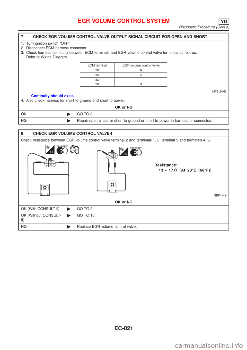
7 CHECK EGR VOLUME CONTROL VALVE OUTPUT SIGNAL CIRCUIT FOR OPEN AND SHORT
1. Turn ignition switch ªOFFº.
2. Disconnect ECM harness connector.
3. Check harness continuity between ECM terminals and EGR volume control valve terminals as follows.
Refer to Wiring Diagram.
MTBL0463
Continuity should exist.
4. Also check harness for short to ground and short to power.
OK or NG
OK©GO TO 8.
NG©Repair open circuit or short to ground or short to power in harness or connectors.
8 CHECK EGR VOLUME CONTROL VALVE-I
Check resistance between EGR volume control valve terminal 2 and terminals 1, 3, terminal 5 and terminals 4, 6.
SEF414Y
OK or NG
OK (With CONSULT-II)©GO TO 9.
OK (Without CONSULT-
II)©GO TO 10.
NG©Replace EGR volume control valve.
EGR VOLUME CONTROL SYSTEMYD
Diagnostic Procedure (Cont'd)
EC-821
Page 1548 of 2898
Diagnostic ProcedureNJEC0770
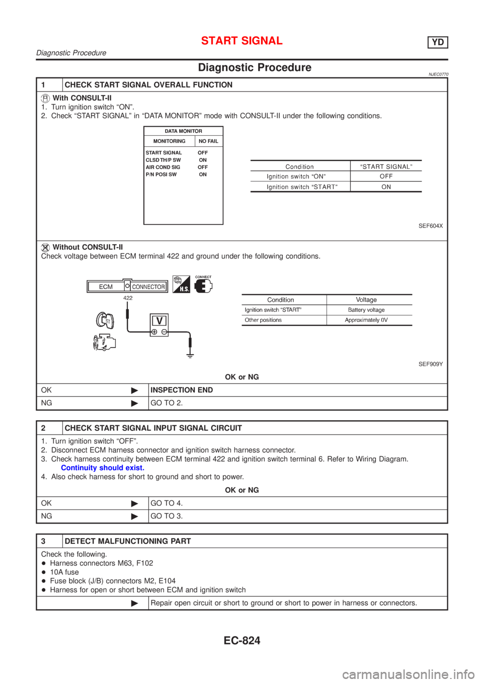
1 CHECK START SIGNAL OVERALL FUNCTION
With CONSULT-II
1. Turn ignition switch ªONº.
2. Check ªSTART SIGNALº in ªDATA MONITORº mode with CONSULT-II under the following conditions.
SEF604X
Without CONSULT-II
Check voltage between ECM terminal 422 and ground under the following conditions.
SEF909Y
OK or NG
OK©INSPECTION END
NG©GO TO 2.
2 CHECK START SIGNAL INPUT SIGNAL CIRCUIT
1. Turn ignition switch ªOFFº.
2. Disconnect ECM harness connector and ignition switch harness connector.
3. Check harness continuity between ECM terminal 422 and ignition switch terminal 6. Refer to Wiring Diagram.
Continuity should exist.
4. Also check harness for short to ground and short to power.
OK or NG
OK©GO TO 4.
NG©GO TO 3.
3 DETECT MALFUNCTIONING PART
Check the following.
+Harness connectors M63, F102
+10A fuse
+Fuse block (J/B) connectors M2, E104
+Harness for open or short between ECM and ignition switch
©Repair open circuit or short to ground or short to power in harness or connectors.
START SIGNALYD
Diagnostic Procedure
EC-824
Page 1552 of 2898

Diagnostic ProcedureNJEC0785
1 CHECK OVERALL FUNCTION
With CONSULT-II
1. Turn ignition switch ªONº.
2. Select ªP/N POSI SWº in ªDATA MONITORº mode with CONSULT-II.
3. Check ªP/N POSI SWº signal under the following conditions.
SEF049Y
Without CONSULT-II
1. Turn ignition switch ªONº.
2. Check voltage between ECM terminal 418 and ground under the following conditions.
SEF914Y
OK or NG
OK©INSPECTION END
NG©GO TO 2.
PARK/NEUTRAL POSITION (PNP) SWITCH (WHERE FITTED)YD
Diagnostic Procedure
EC-828
Page 1553 of 2898
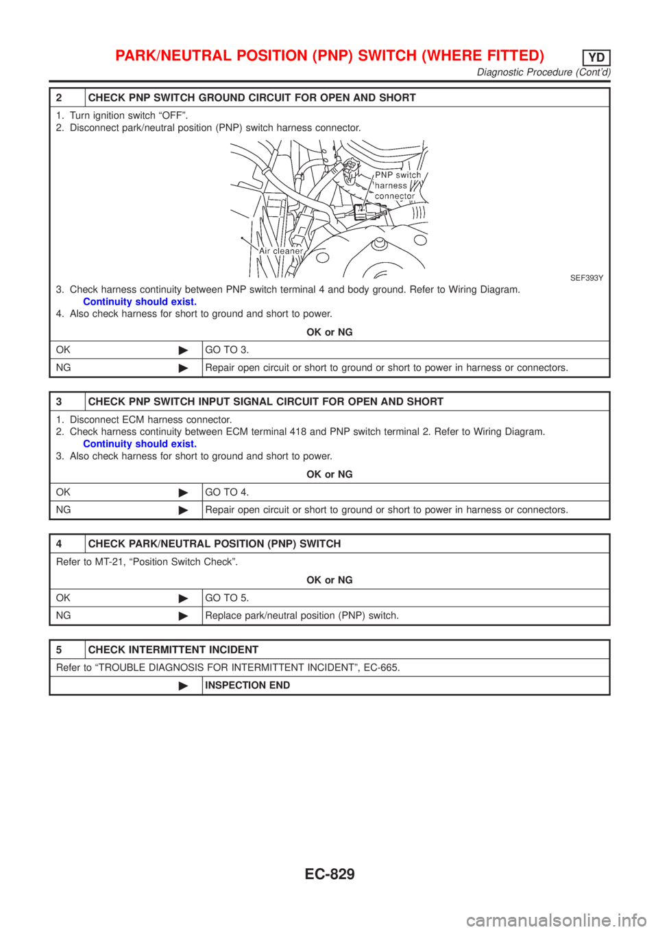
2 CHECK PNP SWITCH GROUND CIRCUIT FOR OPEN AND SHORT
1. Turn ignition switch ªOFFº.
2. Disconnect park/neutral position (PNP) switch harness connector.
SEF393Y
3. Check harness continuity between PNP switch terminal 4 and body ground. Refer to Wiring Diagram.
Continuity should exist.
4. Also check harness for short to ground and short to power.
OK or NG
OK©GO TO 3.
NG©Repair open circuit or short to ground or short to power in harness or connectors.
3 CHECK PNP SWITCH INPUT SIGNAL CIRCUIT FOR OPEN AND SHORT
1. Disconnect ECM harness connector.
2. Check harness continuity between ECM terminal 418 and PNP switch terminal 2. Refer to Wiring Diagram.
Continuity should exist.
3. Also check harness for short to ground and short to power.
OK or NG
OK©GO TO 4.
NG©Repair open circuit or short to ground or short to power in harness or connectors.
4 CHECK PARK/NEUTRAL POSITION (PNP) SWITCH
Refer to MT-21, ªPosition Switch Checkº.
OK or NG
OK©GO TO 5.
NG©Replace park/neutral position (PNP) switch.
5 CHECK INTERMITTENT INCIDENT
Refer to ªTROUBLE DIAGNOSIS FOR INTERMITTENT INCIDENTº, EC-665.
©INSPECTION END
PARK/NEUTRAL POSITION (PNP) SWITCH (WHERE FITTED)YD
Diagnostic Procedure (Cont'd)
EC-829
Page 1559 of 2898
ELECTRICAL SYSTEM
SECTION
EL
CONTENTS
PRECAUTIONS...............................................................5
Supplemental Restraint System (SRS)²AIR
BAG²and²SEAT BELT PRE-TENSIONER²...............5
Wiring Diagrams and Trouble Diagnosis .....................5
HARNESS CONNECTOR................................................6
Description ...................................................................6
STANDARDIZED RELAY................................................8
Description ...................................................................8
POWER SUPPLY ROUTING.........................................10
Schematic/Sedan .......................................................10
Wiring Diagram - POWER -/Sedan With
Gasoline Engine ........................................................ 11
Wiring Diagram - POWER -/Sedan With Diesel
Engine ........................................................................19
Schematic/Hatchback ................................................26
Wiring Diagram - POWER -/Hatchback ....................28
Inspection...................................................................38
GROUND........................................................................39
Ground Distribution ....................................................39
COMBINATION SWITCH..............................................56
Check/Sedan .............................................................56
Check/Hatchback .......................................................57
Replacement ..............................................................58
STEERING SWITCH......................................................59
Check .........................................................................59
HEADLAMP...................................................................60
Wiring Diagram - H/LAMP -/Hatchback.....................60
Wiring Diagram - H/LAMP -/Sedan ...........................61
Trouble Diagnoses.....................................................63
Bulb Replacement .....................................................64
Aiming Adjustment .....................................................65
HEADLAMP - DAYTIME LIGHT SYSTEM -.................67
System Description ....................................................67
Schematic/Sedan .......................................................68
Wiring Diagram - DTRL -/Sedan ...............................69
Schematic/Hatchback ................................................72
Wiring Diagram - DTRL -/Hatchback .........................73
Trouble Diagnoses.....................................................76
Bulb Replacement .....................................................76Aiming Adjustment .....................................................77
HEADLAMP - HEADLAMP AIMING CONTROL -........78
Wiring Diagram - H/AIM -/Sedan...............................78
Wiring Diagram - H/AIM -/Hatchback ........................79
PARKING, LICENSE AND TAIL LAMPS.....................81
Wiring Diagram - TAIL/L -/Sedan ..............................81
Wiring Diagram - TAIL/L -/Hatchback ........................83
STOP LAMP..................................................................85
Wiring Diagram - STOP/L -/Sedan ............................85
Wiring Diagram - STOP/L -/Hatchback .....................86
BACK-UP LAMP............................................................87
Wiring Diagram - BACK/L -/Sedan ............................87
Wiring Diagram - BACK/L -/Hatchback .....................88
FRONT FOG LAMP.......................................................89
Wiring Diagram - F/FOG -/Sedan..............................89
Wiring Diagram - F/FOG -/Hatchback .......................90
Bulb Replacement .....................................................91
Aiming Adjustment .....................................................92
REAR FOG LAMP.........................................................93
Wiring Diagram - R/FOG -/Sedan .............................93
Wiring Diagram - R/FOG -/Hatchback.......................95
TURN SIGNAL AND HAZARD WARNING LAMPS.....96
System Description/Sedan ........................................96
Schematic/Sedan .......................................................98
Wiring Diagram - TURN -/Sedan...............................99
Trouble Diagnoses/Sedan .......................................101
Electrical Components Inspection ...........................101
System Description/Hatchback ................................102
Wiring Diagram - TURN -/Hatchback ......................103
Trouble Diagnoses/Hatchback.................................107
ILLUMINATION............................................................108
Schematic/Sedan .....................................................108
Wiring Diagram - ILL -/Sedan ..................................109
Schematic/Hatchback .............................................. 111
Wiring Diagram - ILL -/Hatchback ........................... 112
INTERIOR ROOM LAMP............................................. 115
System Description/Sedan With Interior Room
Lamp Timer .............................................................. 115
Page 1654 of 2898
System Description/SedanNJEL0030TURN SIGNAL OPERATIONNJEL0030S01With the hazard switch in the OFF position and the ignition switch in the ON or START position, power is sup-
plied
+through 10A fuse [No. 26, located in the fuse block (J/B)]
+to hazard switch terminal 2
+through terminal 1 of the hazard switch
+to combination flasher unit terminal 1
+through terminal 3 of the combination flasher unit
+to turn signal lamp switch terminal 1.
Ground is supplied to combination flasher unit terminal 2 through body grounds M28 and M67.
LH TurnNJEL0030S0101When the turn signal lamp switch is moved to the L position, power is supplied from turn signal lamp switch
terminal 3 to
+front turn signal lamp LH terminal 1 and side turn signal lamp LH terminal 1
+combination meter terminal 11 (with tachometer) or 6 (without tachometer).
+rear combination lamp LH (turn signal) terminal 2.
Ground is supplied to the front turn signal lamp LH terminal 2 and side turn signal lamp LH terminal 2 through
body grounds E30 and E73.
Ground is supplied to the rear combination lamp LH (turn signal) terminal 1 through body grounds B9, B21
and B308.
Ground is supplied to combination meter terminal 56 (with tachometer) or 60 (without tachometer) through
body grounds M28 and M67.
With power and ground supplied, the combination flasher unit controls the flashing of the LH turn signal lamps.
RH TurnNJEL0030S0102When the turn signal lamp switch is moved to the R position, power is supplied from turn signal lamp switch
terminal 2 to
+front turn signal lamp RH terminal 1 and side turn signal lamp RH terminal 1
+combination meter terminal 48 (with tachometer) or 64 (without tachometer)
+rear combination lamp RH (turn signal) terminal 2.
Ground is supplied to the front turn signal lamp RH terminal 2 and side turn signal lamp RH terminal 2 through
body grounds E30 and E73.
Ground is supplied to the rear combination lamp RH (turn signal) terminal 1 through body grounds B9, B21
and B308.
Ground is supplied to combination meter terminal 56 (with tachometer) or 60 (without tachometer) through
body grounds M28 and M67.
With power and ground supplied, the combination flasher unit controls the flashing of the RH turn signal lamps.
HAZARD LAMP OPERATIONNJEL0030S02Power is supplied at all times to hazard switch terminal 3 through:
+15A fuse [No. 5, located in the fuse block (J/B)].
With the hazard switch in the ON position, power is supplied
+through terminal 1 of the hazard switch
+to combination flasher unit terminal 1
+through terminal 3 of the combination flasher unit
+to hazard switch terminal 4.
Ground is supplied to combination flasher unit terminal 2 through body grounds M28 and M67.
Power is supplied through terminal 5 of the hazard switch to
+front turn signal lamp LH terminal 1 and side turn signal lamp LH terminal 1
+combination meter terminal 11 (with tachometer) or 6 (without tachometer)
+rear combination lamp LH (turn signal) terminal 2.
Power is supplied through terminal 6 of the hazard switch to
+front turn signal lamp RH terminal 1 and side turn signal lamp RH terminal 1
TURN SIGNAL AND HAZARD WARNING LAMPS
System Description/Sedan
EL-96