Page 1404 of 2898
SEF594K
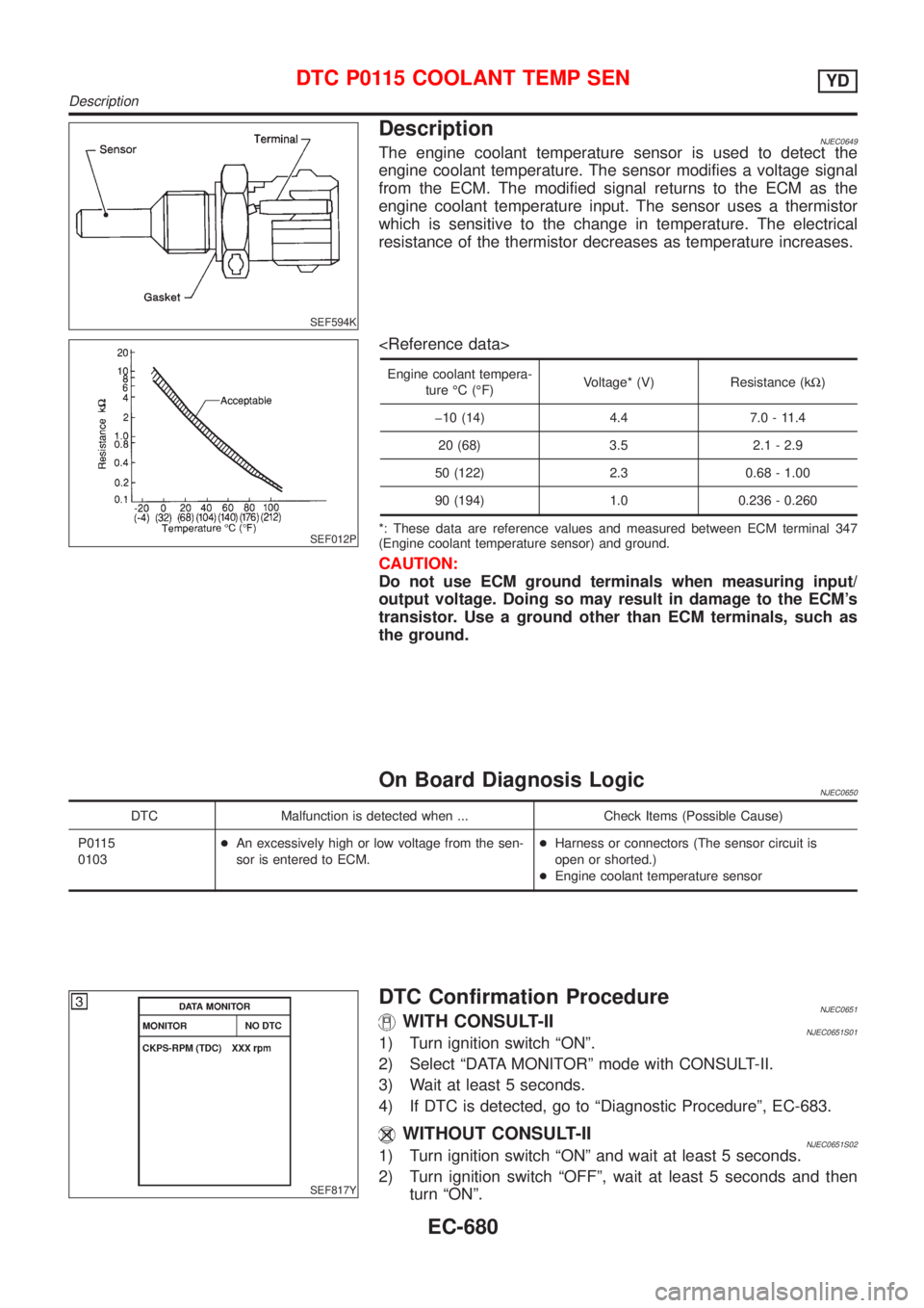
DescriptionNJEC0649The engine coolant temperature sensor is used to detect the
engine coolant temperature. The sensor modifies a voltage signal
from the ECM. The modified signal returns to the ECM as the
engine coolant temperature input. The sensor uses a thermistor
which is sensitive to the change in temperature. The electrical
resistance of the thermistor decreases as temperature increases.
SEF012P
Engine coolant tempera-
ture ÉC (ÉF)Voltage* (V) Resistance (kW)
þ10 (14) 4.4 7.0 - 11.4
20 (68) 3.5 2.1 - 2.9
50 (122) 2.3 0.68 - 1.00
90 (194) 1.0 0.236 - 0.260
*: These data are reference values and measured between ECM terminal 347
(Engine coolant temperature sensor) and ground.
CAUTION:
Do not use ECM ground terminals when measuring input/
output voltage. Doing so may result in damage to the ECM's
transistor. Use a ground other than ECM terminals, such as
the ground.
On Board Diagnosis LogicNJEC0650
DTC Malfunction is detected when ... Check Items (Possible Cause)
P0115
0103+An excessively high or low voltage from the sen-
sor is entered to ECM.+Harness or connectors (The sensor circuit is
open or shorted.)
+Engine coolant temperature sensor
SEF817Y
DTC Confirmation ProcedureNJEC0651WITH CONSULT-IINJEC0651S011) Turn ignition switch ªONº.
2) Select ªDATA MONITORº mode with CONSULT-II.
3) Wait at least 5 seconds.
4) If DTC is detected, go to ªDiagnostic Procedureº, EC-683.
WITHOUT CONSULT-IINJEC0651S021) Turn ignition switch ªONº and wait at least 5 seconds.
2) Turn ignition switch ªOFFº, wait at least 5 seconds and then
turn ªONº.
DTC P0115 COOLANT TEMP SENYD
Description
EC-680
Page 1410 of 2898
![NISSAN ALMERA 2001 Service Manual TERMI-
NAL
NO.WIRE
COLORITEM CONDITION DATA(DC Voltage)
434 W Accelerator position sensor[Ignition switch ªONº]
+Accelerator pedal fully released0.30 - 0.50V
[Ignition switch ªONº]
+Accelerator pe NISSAN ALMERA 2001 Service Manual TERMI-
NAL
NO.WIRE
COLORITEM CONDITION DATA(DC Voltage)
434 W Accelerator position sensor[Ignition switch ªONº]
+Accelerator pedal fully released0.30 - 0.50V
[Ignition switch ªONº]
+Accelerator pe](/manual-img/5/57348/w960_57348-1409.png)
TERMI-
NAL
NO.WIRE
COLORITEM CONDITION DATA(DC Voltage)
434 W Accelerator position sensor[Ignition switch ªONº]
+Accelerator pedal fully released0.30 - 0.50V
[Ignition switch ªONº]
+Accelerator pedal fully depressed3.0 - 4.3V
435 W/GAccelerator position switch
(Idle)[Ignition switch ªONº]
+Accelerator pedal fully releasedApproximately 0V
[Ignition switch ªONº]
+Accelerator pedal depressedBATTERY VOLTAGE
(11 - 14V)
On Board Diagnosis LogicNJEC0682
DTC Malfunction is detected when ... Check Items (Possible Cause)
P0120
0403+The relation between sensor and switch signals
is not in the nomal range during the specified
accelerator positions.+Harness or connectors
(The sensor circuit is open or shorted.)
+Accelerator position sensor
+Accelerator position switch
SEF817Y
DTC Confirmation ProcedureNJEC0683WITH CONSULT-IINJEC0683S011) Turn ignition switch ªONº.
2) Select ªDATA MONITORº mode with CONSULT-II.
3) Depress and release fully accelerator pedal slowly.
4) If DTC is detected, go to ªDiagnostic Procedureº, EC-688.
WITHOUT CONSULT-IINJEC0683S021) Turn ignition switch ªONº.
2) Depress and release fully accelerator pedal slowly.
3) Turn ignition switch ªOFFº, wait at least 5 seconds and then
turn ªONº.
4) Perform ªDiagnostic Test Mode II (Self-diagnostic results)º with
ECM.
5) If DTC is detected, go to ªDiagnostic Procedureº, EC-688.
DTC P0120 ACCEL POS SENSORYD
ECM Terminals and Reference Value (Cont'd)
EC-686
Page 1412 of 2898
Diagnostic ProcedureNJEC0685
1 CHECK ACCELERATOR POSITION SENSOR FUNCTION
With CONSULT-II
1. Turn ignition switch ªONº.
2. Select ªACCEL POS SENº in ªDATA MONITORº mode with CONSULT-II.
3. Check ªACCEL POS SENº signal under the following conditions.
SEF436Z
Without CONSULT-II
1. Turn ignition switch ªONº.
2. Check voltage between ECM terminal 434 and ground under the following conditions.
SEF437Z
OK or NG
OK©GO TO 2.
NG©GO TO 3.
DTC P0120 ACCEL POS SENSORYD
Diagnostic Procedure
EC-688
Page 1415 of 2898
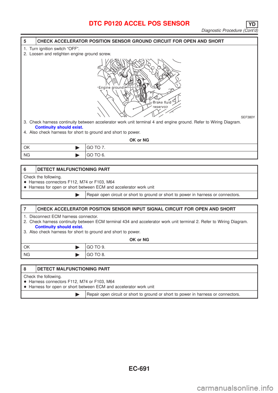
5 CHECK ACCELERATOR POSITION SENSOR GROUND CIRCUIT FOR OPEN AND SHORT
1. Turn ignition switch ªOFFº.
2. Loosen and retighten engine ground screw.
SEF380Y
3. Check harness continuity between accelerator work unit terminal 4 and engine ground. Refer to Wiring Diagram.
Continuity should exist.
4. Also check harness for short to ground and short to power.
OK or NG
OK©GO TO 7.
NG©GO TO 6.
6 DETECT MALFUNCTIONING PART
Check the following.
+Harness connectors F112, M74 or F103, M64
+Harness for open or short between ECM and accelerator work unit
©Repair open circuit or short to ground or short to power in harness or connectors.
7 CHECK ACCELERATOR POSITION SENSOR INPUT SIGNAL CIRCUIT FOR OPEN AND SHORT
1. Disconnect ECM harness connector.
2. Check harness continuity between ECM terminal 434 and accelerator work unit terminal 2. Refer to Wiring Diagram.
Continuity should exist.
3. Also check harness for short to ground and short to power.
OK or NG
OK©GO TO 9.
NG©GO TO 8.
8 DETECT MALFUNCTIONING PART
Check the following.
+Harness connectors F112, M74 or F103, M64
+Harness for open or short between ECM and accelerator work unit
©Repair open circuit or short to ground or short to power in harness or connectors.
DTC P0120 ACCEL POS SENSORYD
Diagnostic Procedure (Cont'd)
EC-691
Page 1422 of 2898
Diagnostic ProcedureNJEC0692
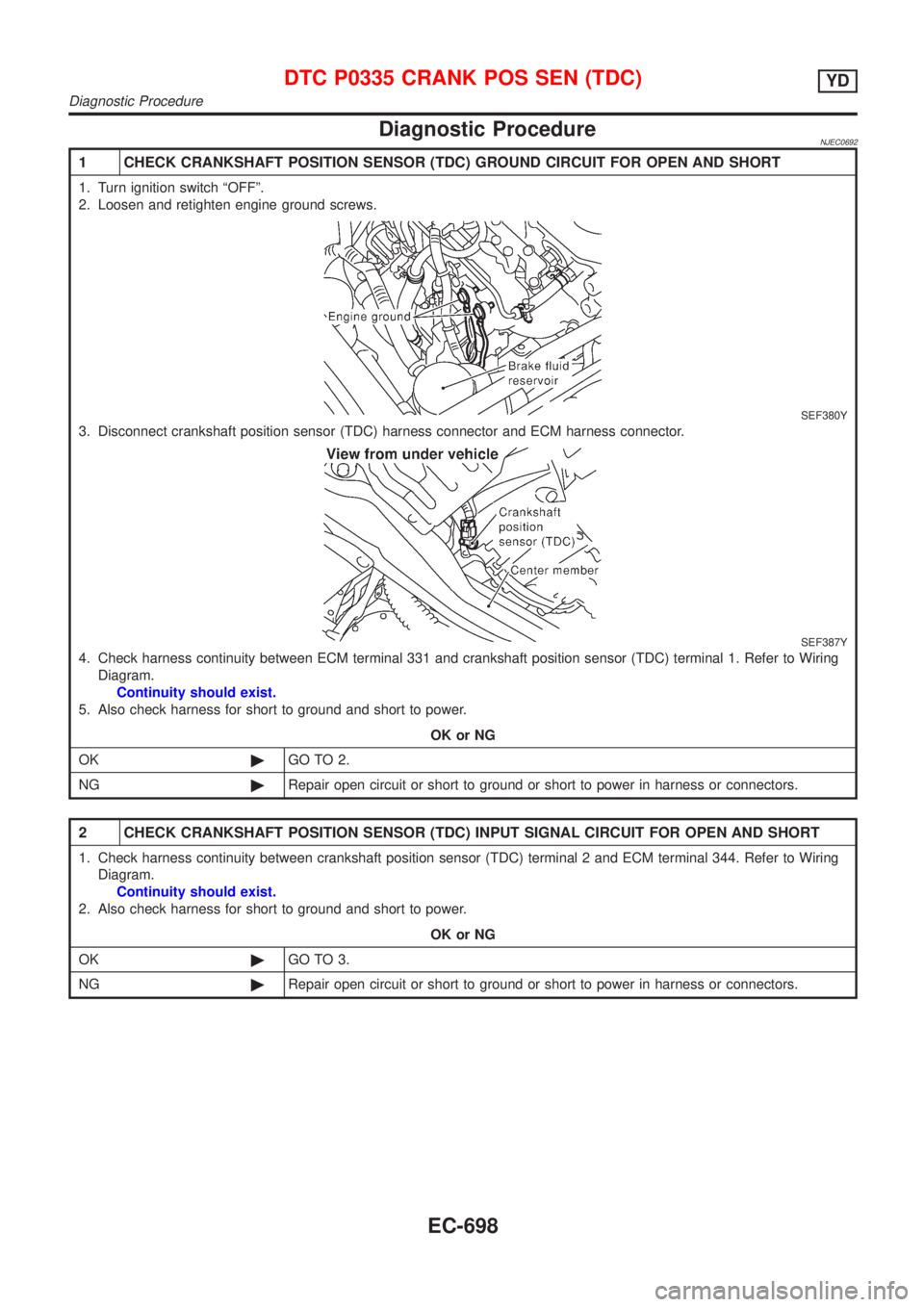
1 CHECK CRANKSHAFT POSITION SENSOR (TDC) GROUND CIRCUIT FOR OPEN AND SHORT
1. Turn ignition switch ªOFFº.
2. Loosen and retighten engine ground screws.
SEF380Y
3. Disconnect crankshaft position sensor (TDC) harness connector and ECM harness connector.
SEF387Y
4. Check harness continuity between ECM terminal 331 and crankshaft position sensor (TDC) terminal 1. Refer to Wiring
Diagram.
Continuity should exist.
5. Also check harness for short to ground and short to power.
OK or NG
OK©GO TO 2.
NG©Repair open circuit or short to ground or short to power in harness or connectors.
2 CHECK CRANKSHAFT POSITION SENSOR (TDC) INPUT SIGNAL CIRCUIT FOR OPEN AND SHORT
1. Check harness continuity between crankshaft position sensor (TDC) terminal 2 and ECM terminal 344. Refer to Wiring
Diagram.
Continuity should exist.
2. Also check harness for short to ground and short to power.
OK or NG
OK©GO TO 3.
NG©Repair open circuit or short to ground or short to power in harness or connectors.
DTC P0335 CRANK POS SEN (TDC)YD
Diagnostic Procedure
EC-698
Page 1429 of 2898
Diagnostic ProcedureNJEC0659
1 CHECK VEHICLE SPEED SENSOR INPUT SIGNAL CIRCUIT FOR OPEN AND SHORT
1. Turn ignition switch ªOFFº.
2. Disconnect ECM harness connector and combination meter harness connector.
3. Check harness continuity between ECM terminal 417 and combination meter terminal 4 or 39 or 57. Refer to Wiring
Diagram.
Continuity should exist.
4. Also check harness for short to ground and short to power.
OK or NG
OK©GO TO 3.
NG©GO TO 2.
2 DETECT MALFUNCTIONING PART
Check the following.
+Harness connectors M63, F102
+Harness for open or short between ECM and combination meter
©Repair open circuit or short to ground or short to power in harness or connectors.
3 CHECK SPEEDOMETER FUNCTION
Make sure that speedometer functions properly.
OK or NG
OK©GO TO 5.
NG©GO TO 4.
4 CHECK SPEEDOMETER CIRCUIT FOR OPEN AND SHORT
Check the following.
+Harness connectors M63, F102
+Harness for open or short between vehicle speed sensor and engine ground
+Harness for open or short between combination meter and vehicle speed sensor
OK or NG
OK©Check vehicle speed sensor and combination meter. Refer to EL section.
NG©Repair open circuit or short to ground or short to power in harness or connectors.
5 CHECK INTERMITTENT INCIDENT
Refer to ªTROUBLE DIAGNOSIS FOR INTERMITTENT INCIDENTº, EC-665.
©INSPECTION END
DTC P0500 VEHICLE SPEED SENYD
Diagnostic Procedure
EC-705
Page 1430 of 2898
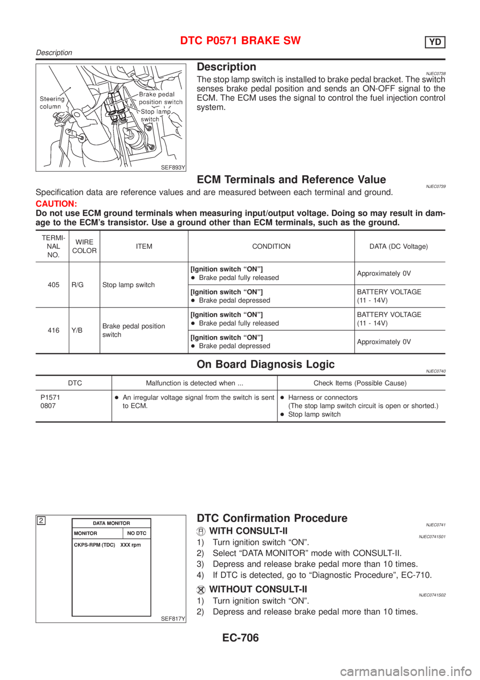
SEF893Y
DescriptionNJEC0738The stop lamp switch is installed to brake pedal bracket. The switch
senses brake pedal position and sends an ON-OFF signal to the
ECM. The ECM uses the signal to control the fuel injection control
system.
ECM Terminals and Reference ValueNJEC0739Specification data are reference values and are measured between each terminal and ground.
CAUTION:
Do not use ECM ground terminals when measuring input/output voltage. Doing so may result in dam-
age to the ECM's transistor. Use a ground other than ECM terminals, such as the ground.
TERMI-
NAL
NO.WIRE
COLORITEM CONDITION DATA (DC Voltage)
405 R/G Stop lamp switch[Ignition switch ªONº]
+Brake pedal fully releasedApproximately 0V
[Ignition switch ªONº]
+Brake pedal depressedBATTERY VOLTAGE
(11 - 14V)
416 Y/BBrake pedal position
switch[Ignition switch ªONº]
+Brake pedal fully releasedBATTERY VOLTAGE
(11 - 14V)
[Ignition switch ªONº]
+Brake pedal depressedApproximately 0V
On Board Diagnosis LogicNJEC0740
DTC Malfunction is detected when ... Check Items (Possible Cause)
P1571
0807+An irregular voltage signal from the switch is sent
to ECM.+Harness or connectors
(The stop lamp switch circuit is open or shorted.)
+Stop lamp switch
SEF817Y
DTC Confirmation ProcedureNJEC0741WITH CONSULT-IINJEC0741S011) Turn ignition switch ªONº.
2) Select ªDATA MONITORº mode with CONSULT-II.
3) Depress and release brake pedal more than 10 times.
4) If DTC is detected, go to ªDiagnostic Procedureº, EC-710.
WITHOUT CONSULT-IINJEC0741S021) Turn ignition switch ªONº.
2) Depress and release brake pedal more than 10 times.
DTC P0571 BRAKE SWYD
Description
EC-706
Page 1435 of 2898
4 CHECK STOP LAMP SWITCH INPUT SIGNAL CIRCUIT FOR OPEN AND SHORT
1. Turn ignition switch ªOFFº.
2. Disconnect ECM harness connector.
3. Disconnect stop lamp switch harness connector.
SEF893Y
4. Check harness continuity between ECM terminal 405 and stop lamp switch terminal 2. Refer to Wiring Diagram.
Continuity should exist.
5. Also check harness for short to ground and short to power.
OK or NG
OK©GO TO 6.
NG©GO TO 5.
5 DETECT MALFUNCTIONING PART
Check the following.
+Harness connectors M74, F112 or M64, F103
+Harness for open or short between ECM and stop lamp switch
©Repair open circuit or short to ground or short to power in harness or connectors.
6 CHECK STOP LAMP SWITCH
Check continuity between stop lamp switch terminals 1 and 2 under the following conditions.
SEF904Y
OK or NG
OK©GO TO 7.
NG©Replace stop lamp switch.
DTC P0571 BRAKE SWYD
Diagnostic Procedure (Cont'd)
EC-711