Page 1307 of 2898
Diagnostic Procedure Ð Load Signal ÐNJEC0584
1 INSPECTION START
Do you have CONSULT-II?
YesorNo
Ye s©GO TO 2.
No©GO TO 4.
2 CHECK LOAD SIGNAL CIRCUIT OVERALL FUNCTION-I
With CONSULT-II
1. Turn ignition switch ªONº.
2. Check ªLOAD SIGNALº in ªDATA MONITORº mode with CONSULT-II under the following conditions.
SEF954X
OK or NG
OK©GO TO 3.
NG©GO TO 6.
3 CHECK LOAD SIGNAL CIRCUIT OVERALL FUNCTION-II
With CONSULT-II
1. Turn ignition switch ªONº.
2. Check ªLOAD SIGNALº in ªDATA MONITORº mode with CONSULT-II under the following conditions.
SEF955X
OK or NG
OK©INSPECTION END
NG©GO TO 14.
ELECTRICAL LOAD SIGNALQG
Diagnostic Procedure Ð Load Signal Ð
EC-583
Page 1308 of 2898
4 CHECK LOAD SIGNAL CIRCUIT OVERALL FUNCTION-I
Without CONSULT-II
1. Turn ignition switch ªONº.
2. Check voltage between ECM terminal 50 and ground under the following conditions.
SEF956X
OK or NG
OK©GO TO 5.
NG©GO TO 6.
5 CHECK LOAD SIGNAL CIRCUIT OVERALL FUNCTION-II
Without CONSULT-II
1. Turn ignition switch ªONº.
2. Check voltage between ECM terminal 50 and ground under the following conditions.
SEF957X
OK or NG
OK©INSPECTION END
NG©GO TO 15.
6 CHECK REAR WINDOW DEFOGGER FUNCTION
1. Start engine.
2. Turn ªONº the rear window defogger switch.
3. Check the rear windshield. Is the rear windshield heated up?
YesorNo
Yes (Sedan)©GO TO 7.
Yes (Hatchback)©GO TO 12.
No©Refer to EL-240, ªRear Window Defoggerº.
ELECTRICAL LOAD SIGNALQG
Diagnostic Procedure Ð Load Signal Ð (Cont'd)
EC-584
Page 1309 of 2898
7 CHECK POWER SUPPLY
1. Stop engine.
2. Turn ªOFFº the rear window defogger switch.
3. Disconnect rear window defogger relay.
4. Check voltage between terminal 3 (LHD models), 5 (RHD models) and ground with CONSULT-II or tester.
SEF626Z
OK or NG
OK©GO TO 8.
NG©Check the following and repair.
+20A fuse
+Harness for open and short between fuse block and rear window defogger relay
8 CHECK REAR WINDOW DEFOGGER RELAY
Refer to ªComponent Inspectionº, EC-590.
OK or NG
OK©GO TO 9.
NG©Replace rear window defogger relay.
9 CHECK REAR WINDOW DEFOGGER INPUT SIGNAL CIRCUIT
1. Disconnect ECM harness connector.
2. Check harness continuity between ECM terminal 50 and rear window defogger relay terminals 5 (LHD models), 3 (RHD
models).
Refer to wiring diagram.
SEF627Z
3. Also check harness for short to ground and short to power.
OK or NG
OK©GO TO 11.
NG©GO TO 10.
ELECTRICAL LOAD SIGNALQG
Diagnostic Procedure Ð Load Signal Ð (Cont'd)
EC-585
Page 1336 of 2898

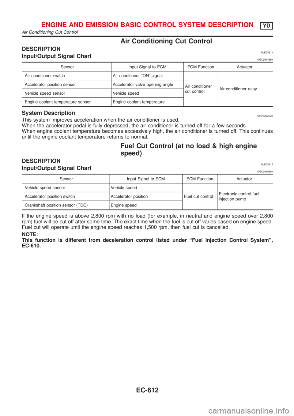
Air Conditioning Cut Control
DESCRIPTIONNJEC0614Input/Output Signal ChartNJEC0614S01
Sensor Input Signal to ECM ECM Function Actuator
Air conditioner switch Air conditioner ªONº signal
Air conditioner
cut controlAir conditioner relay Accelerator position sensor Accelerator valve opening angle
Vehicle speed sensor Vehicle speed
Engine coolant temperature sensor Engine coolant temperature
System DescriptionNJEC0614S02This system improves acceleration when the air conditioner is used.
When the accelerator pedal is fully depressed, the air conditioner is turned off for a few seconds.
When engine coolant temperature becomes excessively high, the air conditioner is turned off. This continues
until the engine coolant temperature returns to normal.
Fuel Cut Control (at no load & high engine
speed)
DESCRIPTIONNJEC0615Input/Output Signal ChartNJEC0615S01
Sensor Input Signal to ECM ECM Function Actuator
Vehicle speed sensor Vehicle speed
Fuel cut controlElectronic control fuel
injection pump Accelerator position switch Accelerator position
Crankshaft position sensor (TDC) Engine speed
If the engine speed is above 2,800 rpm with no load (for example, in neutral and engine speed over 2,800
rpm) fuel will be cut off after some time. The exact time when the fuel is cut off varies based on engine speed.
Fuel cut will operate until the engine speed reaches 1,500 rpm, then fuel cut is cancelled.
NOTE:
This function is different from deceleration control listed under ªFuel Injection Control Systemº,
EC-610.
ENGINE AND EMISSION BASIC CONTROL SYSTEM DESCRIPTIONYD
Air Conditioning Cut Control
EC-612
Page 1377 of 2898
SYSTEM Ð ENGINE CONTROL system
Malfunction
SYMPTOM
Reference page
Feature of symptom, Check pointROUGH IDLE/HUNTING
IDLING VIBRATION
SLOW/NO RETURN TO IDLE
OVERHEAT/HIGH ENGINE COOLANT TEMPERATURE
EXCESSIVE FUEL CONSUMPTION
EXCESSIVE OIL CONSUMPTION
ABNORMAL SMOKE COLOR
DEAD BATTERY (UNDER CHARGE)
Malfunction indicator illuminates.
Can be detected by CONSULT-II?BLACK SMOKE
WHITE SMOKEWarranty symptom code AG AH AJ AK AL AM AP HA
ENGINE CONTROL
Start signal circuit *a, *b EC-823 *3
Accelerator position switch (Idle) circuit*a, *c
EC-685
*b 1 1 *4
Ignition switch circuit*a
EC-666
*b*5
Power supply for ECM circuit*a
1 1 EC-666
*b
1 - 5: The numbers refer to the order of inspection.
(continued on next page)
*a: Open
*b: Short
*c: Ground short
*d: Noise
*3: Start control does not function.
*4: Accelerator position sensor NG signal is output.
*5: Engine does not stop.
TROUBLE DIAGNOSIS Ð GENERAL DESCRIPTIONYD
Symptom Matrix Chart (Cont'd)
EC-653
Page 1380 of 2898

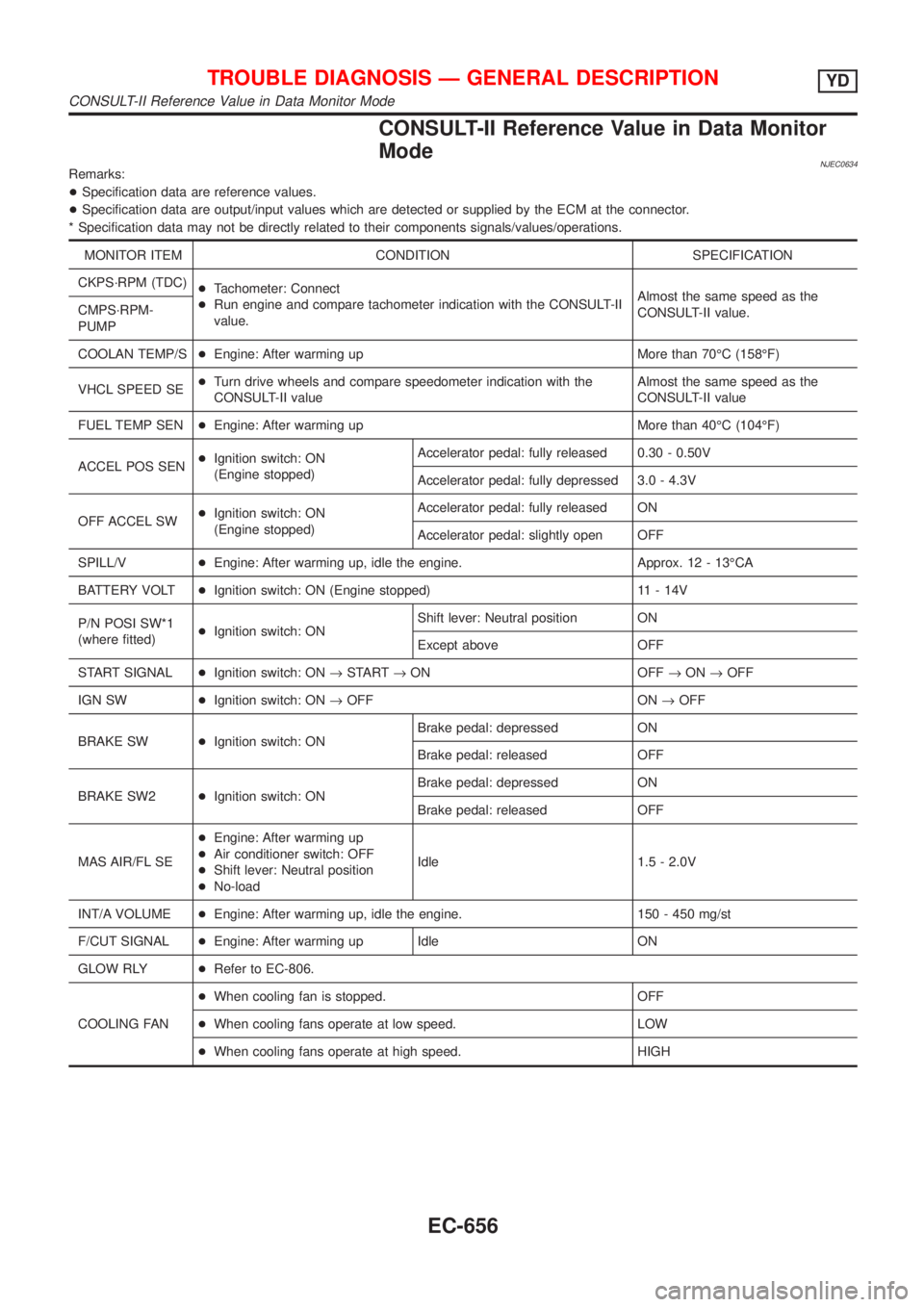
CONSULT-II Reference Value in Data Monitor
Mode
NJEC0634Remarks:
+Specification data are reference values.
+Specification data are output/input values which are detected or supplied by the ECM at the connector.
* Specification data may not be directly related to their components signals/values/operations.
MONITOR ITEM CONDITION SPECIFICATION
CKPS´RPM (TDC)
+Tachometer: Connect
+Run engine and compare tachometer indication with the CONSULT-II
value.Almost the same speed as the
CONSULT-II value. CMPS´RPM-
PUMP
COOLAN TEMP/S+Engine: After warming up More than 70ÉC (158ÉF)
VHCL SPEED SE+Turn drive wheels and compare speedometer indication with the
CONSULT-II valueAlmost the same speed as the
CONSULT-II value
FUEL TEMP SEN+Engine: After warming up More than 40ÉC (104ÉF)
ACCEL POS SEN+Ignition switch: ON
(Engine stopped)Accelerator pedal: fully released 0.30 - 0.50V
Accelerator pedal: fully depressed 3.0 - 4.3V
OFF ACCEL SW+Ignition switch: ON
(Engine stopped)Accelerator pedal: fully released ON
Accelerator pedal: slightly open OFF
SPILL/V+Engine: After warming up, idle the engine. Approx. 12 - 13ÉCA
BATTERY VOLT+Ignition switch: ON (Engine stopped) 11 - 14V
P/N POSI SW*1
(where fitted)+Ignition switch: ONShift lever: Neutral position ON
Except above OFF
START SIGNAL+Ignition switch: ON®START®ON OFF®ON®OFF
IGN SW+Ignition switch: ON®OFF ON®OFF
BRAKE SW+Ignition switch: ONBrake pedal: depressed ON
Brake pedal: released OFF
BRAKE SW2+Ignition switch: ONBrake pedal: depressed ON
Brake pedal: released OFF
MAS AIR/FL SE+Engine: After warming up
+Air conditioner switch: OFF
+Shift lever: Neutral position
+No-loadIdle 1.5 - 2.0V
INT/A VOLUME+Engine: After warming up, idle the engine. 150 - 450 mg/st
F/CUT SIGNAL+Engine: After warming up Idle ON
GLOW RLY+Refer to EC-806.
COOLING FAN+When cooling fan is stopped. OFF
+When cooling fans operate at low speed. LOW
+When cooling fans operate at high speed. HIGH
TROUBLE DIAGNOSIS Ð GENERAL DESCRIPTIONYD
CONSULT-II Reference Value in Data Monitor Mode
EC-656
Page 1385 of 2898
![NISSAN ALMERA 2001 Service Manual TERMI-
NAL
NO.WIRE
COLORITEM CONDITIONDATA (DC Voltage and Pulse
Signal)
104
105
106B
B
BECM ground[Engine is running]
+Idle speedApproximately 0V
107
108
109R
R
RPower supply for ECM[Ignition switch NISSAN ALMERA 2001 Service Manual TERMI-
NAL
NO.WIRE
COLORITEM CONDITIONDATA (DC Voltage and Pulse
Signal)
104
105
106B
B
BECM ground[Engine is running]
+Idle speedApproximately 0V
107
108
109R
R
RPower supply for ECM[Ignition switch](/manual-img/5/57348/w960_57348-1384.png)
TERMI-
NAL
NO.WIRE
COLORITEM CONDITIONDATA (DC Voltage and Pulse
Signal)
104
105
106B
B
BECM ground[Engine is running]
+Idle speedApproximately 0V
107
108
109R
R
RPower supply for ECM[Ignition switch ªONº]BATTERY VOLTAGE
(11 - 14V)
204 L Air conditioner relay[Engine is running]
+Air conditioner switch is ªOFFºBATTERY VOLTAGE
(11 - 14V)
[Engine is running]
+Both air conditioner switch and blower fan
switch are ªONº
(Compressor is operating)Approximately 0.1V
214 W/B Glow relay Refer to ªGlow Control Systemº, EC-806.
218 B Sensors' ground[Engine is running]
+Warm-up condition
+Idle speedApproximately 0V
219 LG/R Cooling fan relay (Low)[Engine is running]
+Cooling fan is not operatingBATTERY VOLTAGE
(11 - 14V)
[Engine is running]
+Cooling fan is operatingApproximately 0.1V
221 LG/B Cooling fan relay (High)[Engine is running]
+Cooling fan is not operating
+Cooling fan is operating at low speedBATTERY VOLTAGE
(11 - 14V)
[Engine is running]
+Cooling fan is operating at high speedApproximately 0.1V
223 WMass air flow sensor
power supply[Ignition switch ªONº]Approximately 5V
224 R Mass air flow sensor[Engine is running]
+Warm-up condition
+Idle speed1.5 - 2.0V
313 L/WElectronic control fuel
injection pump[Engine is running]
+Warm-up condition
+Idle speedApproximately 0.1V
314 L/RElectronic control fuel
injection pump[Engine is running]
+Warm-up condition
+Idle speedApproximately 0.4V
316 PUElectronic control fuel
injection pump[Engine is running]
+Warm-up condition
+Idle speedApproximately 2.5V
317 PElectronic control fuel
injection pump[Engine is running]
+Warm-up condition
+Idle speedApproximately 2.5V
325 G ECM relay (Self-shutoff)[Ignition switch ªONº]
[Ignition switch ªOFFº]
+For a few seconds after turning ignition switch
ªOFFºApproximately 0.25V
[Ignition switch ªOFFº]
+A few seconds passed after turning ignition
switch ªOFFºBATTERY VOLTAGE
(11 - 14V)
TROUBLE DIAGNOSIS Ð GENERAL DESCRIPTIONYD
ECM Terminals and Reference Value (Cont'd)
EC-661
Page 1402 of 2898

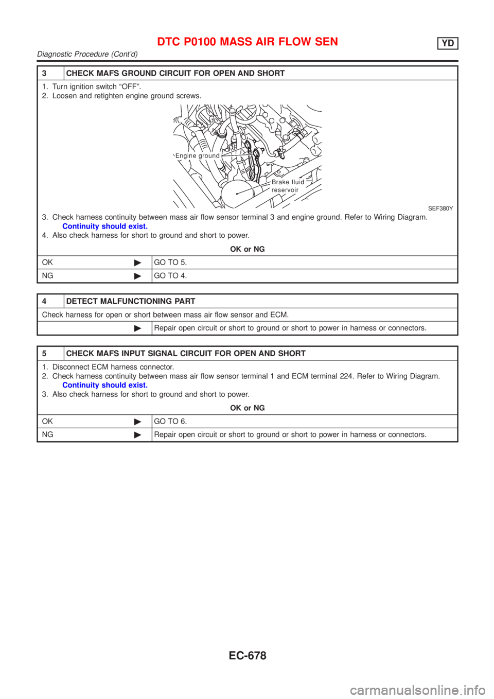
3 CHECK MAFS GROUND CIRCUIT FOR OPEN AND SHORT
1. Turn ignition switch ªOFFº.
2. Loosen and retighten engine ground screws.
SEF380Y
3. Check harness continuity between mass air flow sensor terminal 3 and engine ground. Refer to Wiring Diagram.
Continuity should exist.
4. Also check harness for short to ground and short to power.
OK or NG
OK©GO TO 5.
NG©GO TO 4.
4 DETECT MALFUNCTIONING PART
Check harness for open or short between mass air flow sensor and ECM.
©Repair open circuit or short to ground or short to power in harness or connectors.
5 CHECK MAFS INPUT SIGNAL CIRCUIT FOR OPEN AND SHORT
1. Disconnect ECM harness connector.
2. Check harness continuity between mass air flow sensor terminal 1 and ECM terminal 224. Refer to Wiring Diagram.
Continuity should exist.
3. Also check harness for short to ground and short to power.
OK or NG
OK©GO TO 6.
NG©Repair open circuit or short to ground or short to power in harness or connectors.
DTC P0100 MASS AIR FLOW SENYD
Diagnostic Procedure (Cont'd)
EC-678