2001 NISSAN ALMERA turn signal
[x] Cancel search: turn signalPage 1995 of 2898
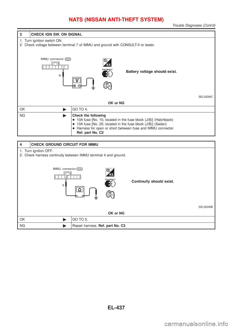
3 CHECK IGN SW. ON SIGNAL
1. Turn ignition switch ON.
2. Check voltage between terminal 7 of IMMU and ground with CONSULT-II or tester.
SEL303WC
OK or NG
OK©GO TO 4.
NG©Check the following
+10A fuse [No. 10, located in the fuse block (J/B)] (Hatchback)
+10A fuse [No. 20, located in the fuse block (J/B)] (Sedan)
+Harness for open or short between fuse and IMMU connector
Ref. part No. C2
4 CHECK GROUND CIRCUIT FOR IMMU
1. Turn ignition OFF.
2. Check harness continuity between IMMU terminal 4 and ground.
SEL304WB
OK or NG
OK©GO TO 5.
NG©Repair harness.Ref. part No. C3
NATS (NISSAN ANTI-THEFT SYSTEM)
Trouble Diagnoses (Cont'd)
EL-437
Page 1997 of 2898
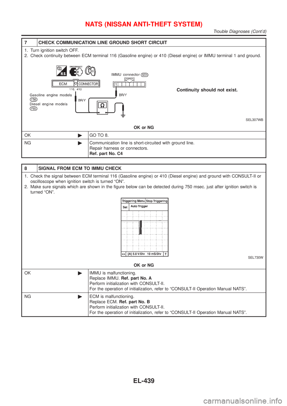
7 CHECK COMMUNICATION LINE GROUND SHORT CIRCUIT
1. Turn ignition switch OFF.
2. Check continuity between ECM terminal 116 (Gasoline engine) or 410 (Diesel engine) or IMMU terminal 1 and ground.
SEL307WB
OK or NG
OK©GO TO 8.
NG©Communication line is short-circuited with ground line.
Repair harness or connectors.
Ref. part No. C4
8 SIGNAL FROM ECM TO IMMU CHECK
1. Check the signal between ECM terminal 116 (Gasoline engine) or 410 (Diesel engine) and ground with CONSULT-II or
oscilloscope when ignition switch is turned ªONº.
2. Make sure signals which are shown in the figure below can be detected during 750 msec. just after ignition switch is
turned ªONº.
SEL730W
OK or NG
OK©IMMU is malfunctioning.
Replace IMMU.Ref. part No. A
Perform initialization with CONSULT-II.
For the operation of initialization, refer to ªCONSULT-II Operation Manual NATSº.
NG©ECM is malfunctioning.
Replace ECM.Ref. part No. B
Perform initialization with CONSULT-II.
For the operation of initialization, refer to ªCONSULT-II Operation Manual NATSº.
NATS (NISSAN ANTI-THEFT SYSTEM)
Trouble Diagnoses (Cont'd)
EL-439
Page 2034 of 2898
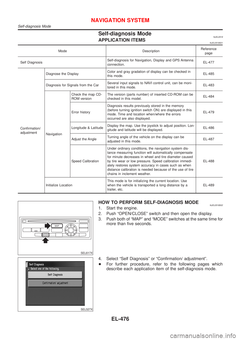
Self-diagnosis ModeNJEL0519APPLICATION ITEMSNJEL0519S01
Mode DescriptionReference
page
Self DiagnosisSelf-diagnosis for Navigation, Display and GPS Antenna
connection.EL-477
Confirmation/
adjustmentDiagnose the DisplayColor and gray gradation of display can be checked in
this mode.EL-485
Diagnosis for Signals from the CarSeveral input signals to NAVI control unit, can be moni-
tored in this mode.EL-483
NavigationCheck the map CD-
ROM versionThe version (parts number) of inserted CD-ROM can be
checked in this model.EL-484
Error historyDiagnosis results previously stored in the memory
(before turning ignition switch ON) are displayed in this
mode. Time and location when/where the errors
occurred are also displayed.EL-479
Longitude & LatitudeDisplay the map. Use the joystick to adjust position. Lon-
gitude and latitude will be displayed.EL-486
Adjust the AngleTurning angle of the vehicle on the display can be
adjusted in this mode.EL-487
Speed CalibrationUnder ordinary conditions, the navigation system dis-
tance measuring function will automatically compensate
for minute decreases in wheel and tire diameter caused
by tire wear or low pressure. Speed calibration immedi-
ately restores system accuracy in cases such as when
distance calibration is needed because of the use of tire
chains in inclement weather.EL-488
Initialize LocationThis mode is for initializing the current location. Use
when the vehicle is transported a long distance by a
trailer, etc.EL-489
MODEMAP
SEL617X
HOW TO PERFORM SELF-DIAGNOSIS MODENJEL0519S021. Start the engine.
2. Push ªOPEN/CLOSEº switch and then open the display.
3. Push both of ªMAPº and ªMODEº switches at the same time for
more than five seconds.
SEL527X
4. Select ªSelf Diagnosisº or ªConfirmation/ adjustmentº.
+For further procedure, refer to the following pages which
describe each application item of the self-diagnosis mode.
NAVIGATION SYSTEM
Self-diagnosis Mode
EL-476
Page 2059 of 2898
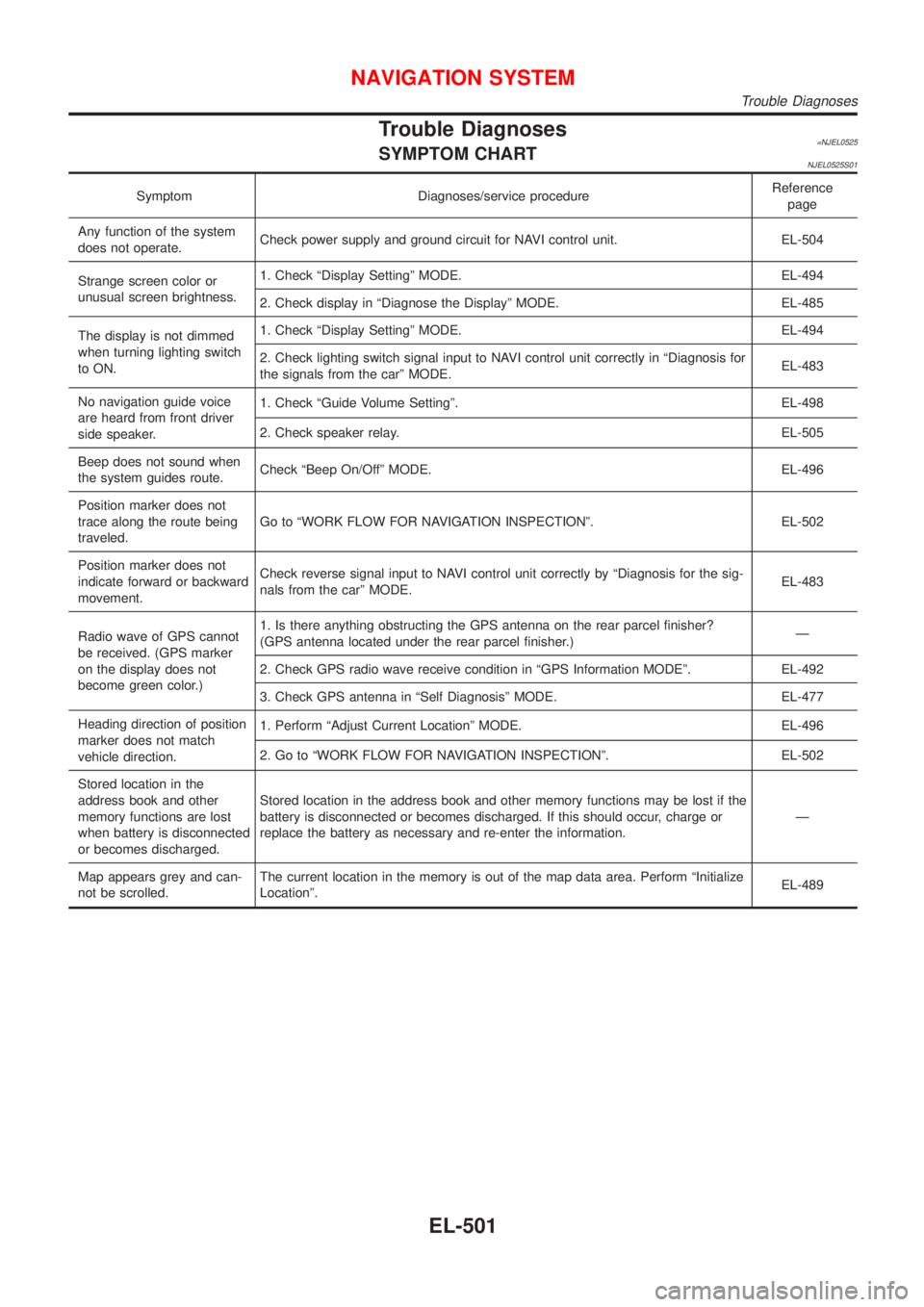
Trouble Diagnoses=NJEL0525SYMPTOM CHARTNJEL0525S01
Symptom Diagnoses/service procedureReference
page
Any function of the system
does not operate.Check power supply and ground circuit for NAVI control unit. EL-504
Strange screen color or
unusual screen brightness.1. Check ªDisplay Settingº MODE. EL-494
2. Check display in ªDiagnose the Displayº MODE. EL-485
The display is not dimmed
when turning lighting switch
to ON.1. Check ªDisplay Settingº MODE. EL-494
2. Check lighting switch signal input to NAVI control unit correctly in ªDiagnosis for
the signals from the carº MODE.EL-483
No navigation guide voice
are heard from front driver
side speaker.1. Check ªGuide Volume Settingº. EL-498
2. Check speaker relay. EL-505
Beep does not sound when
the system guides route.Check ªBeep On/Offº MODE. EL-496
Position marker does not
trace along the route being
traveled.Go to ªWORK FLOW FOR NAVIGATION INSPECTIONº. EL-502
Position marker does not
indicate forward or backward
movement.Check reverse signal input to NAVI control unit correctly by ªDiagnosis for the sig-
nals from the carº MODE.EL-483
Radio wave of GPS cannot
be received. (GPS marker
on the display does not
become green color.)1. Is there anything obstructing the GPS antenna on the rear parcel finisher?
(GPS antenna located under the rear parcel finisher.)Ð
2. Check GPS radio wave receive condition in ªGPS Information MODEº. EL-492
3. Check GPS antenna in ªSelf Diagnosisº MODE. EL-477
Heading direction of position
marker does not match
vehicle direction.1. Perform ªAdjust Current Locationº MODE. EL-496
2. Go to ªWORK FLOW FOR NAVIGATION INSPECTIONº. EL-502
Stored location in the
address book and other
memory functions are lost
when battery is disconnected
or becomes discharged.Stored location in the address book and other memory functions may be lost if the
battery is disconnected or becomes discharged. If this should occur, charge or
replace the battery as necessary and re-enter the information.Ð
Map appears grey and can-
not be scrolled.The current location in the memory is out of the map data area. Perform ªInitialize
Locationº.EL-489
NAVIGATION SYSTEM
Trouble Diagnoses
EL-501
Page 2070 of 2898
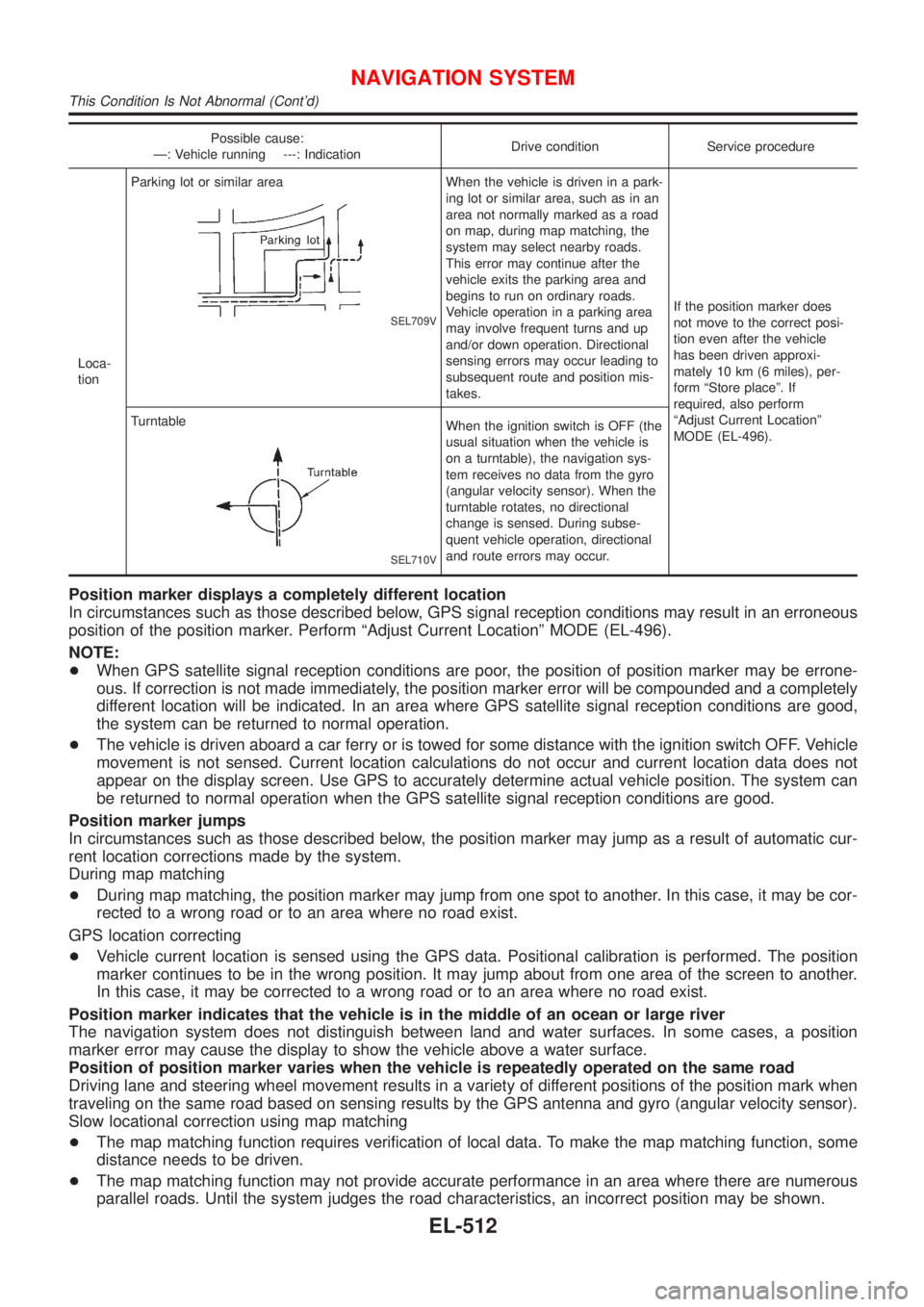
Possible cause:
Ð: Vehicle running ---: IndicationDrive condition Service procedure
Loca-
tionParking lot or similar area
SEL709V
When the vehicle is driven in a park-
ing lot or similar area, such as in an
area not normally marked as a road
on map, during map matching, the
system may select nearby roads.
This error may continue after the
vehicle exits the parking area and
begins to run on ordinary roads.
Vehicle operation in a parking area
may involve frequent turns and up
and/or down operation. Directional
sensing errors may occur leading to
subsequent route and position mis-
takes.If the position marker does
not move to the correct posi-
tion even after the vehicle
has been driven approxi-
mately 10 km (6 miles), per-
form ªStore placeº. If
required, also perform
ªAdjust Current Locationº
MODE (EL-496). Turntable
SEL710V
When the ignition switch is OFF (the
usual situation when the vehicle is
on a turntable), the navigation sys-
tem receives no data from the gyro
(angular velocity sensor). When the
turntable rotates, no directional
change is sensed. During subse-
quent vehicle operation, directional
and route errors may occur.
Position marker displays a completely different location
In circumstances such as those described below, GPS signal reception conditions may result in an erroneous
position of the position marker. Perform ªAdjust Current Locationº MODE (EL-496).
NOTE:
+When GPS satellite signal reception conditions are poor, the position of position marker may be errone-
ous. If correction is not made immediately, the position marker error will be compounded and a completely
different location will be indicated. In an area where GPS satellite signal reception conditions are good,
the system can be returned to normal operation.
+The vehicle is driven aboard a car ferry or is towed for some distance with the ignition switch OFF. Vehicle
movement is not sensed. Current location calculations do not occur and current location data does not
appear on the display screen. Use GPS to accurately determine actual vehicle position. The system can
be returned to normal operation when the GPS satellite signal reception conditions are good.
Position marker jumps
In circumstances such as those described below, the position marker may jump as a result of automatic cur-
rent location corrections made by the system.
During map matching
+During map matching, the position marker may jump from one spot to another. In this case, it may be cor-
rected to a wrong road or to an area where no road exist.
GPS location correcting
+Vehicle current location is sensed using the GPS data. Positional calibration is performed. The position
marker continues to be in the wrong position. It may jump about from one area of the screen to another.
In this case, it may be corrected to a wrong road or to an area where no road exist.
Position marker indicates that the vehicle is in the middle of an ocean or large river
The navigation system does not distinguish between land and water surfaces. In some cases, a position
marker error may cause the display to show the vehicle above a water surface.
Position of position marker varies when the vehicle is repeatedly operated on the same road
Driving lane and steering wheel movement results in a variety of different positions of the position mark when
traveling on the same road based on sensing results by the GPS antenna and gyro (angular velocity sensor).
Slow locational correction using map matching
+The map matching function requires verification of local data. To make the map matching function, some
distance needs to be driven.
+The map matching function may not provide accurate performance in an area where there are numerous
parallel roads. Until the system judges the road characteristics, an incorrect position may be shown.
NAVIGATION SYSTEM
This Condition Is Not Abnormal (Cont'd)
EL-512
Page 2071 of 2898
GPS signal reception conditions are good. However, the position mark does not return to its proper
position.
+The system senses the vehicle location with an error of approximately 100 m (328 ft). Due to the limita-
tion of precision, the position marker may be inaccurate even if the GPS signal reception condition is good.
+The navigation system uses GPS data to determine vehicle location. GPS data is compared with other
locational sensing data during the map matching process. The system decides which data is more pre-
cise and uses that data.
+When the vehicle is stationary, GPS data cannot be used to make system corrections.
Area designations on the map display and the BIRDVIEW
Tdisplay differ.
To prevent the display from becoming congested, alphanumeric information is abridged.
[No problem]
Correct position of your vehicle is not displayed.
Vehicle position changed after ignition key was turned to the OFF position (Vehicle is transported on car ferry,
car train, or by some other means).
[Operate vehicle for short time under GPS receiving conditions.]
The display does not change to night-time mode even though the light switch has been turned ON.
Lights have been turned on. In ªDISPLAY CHANGEº mode, night-time mode on display has been switched to
day-time mode and still is.
[Turn lights on again. Set the display to night-time mode. Refer to EL-494.]
Map does not scroll even though the position of your vehicle is changed.
Present area does not appear on the display.
[Press the ªMAPº switch.]
Vehicle position marker does not appear.
Present area does not appear on the display.
[Press the ªMAPº switch.]
The map surface precision display (GPS satellite marker) still remains gray.
Vehicle is parked inside a building or in the shadow of a large building. This intercepts the GPS signal.
[Move the vehicle to a more open position.]
GPS signal is not received because objects are placed on the rear parcel shelf.
[Remove objects from the rear parcel shelf.]
GPS satellite position is bad.
[Wait until GPS satellite position improves.]
Vehicle position precision is bad.
The map surface precision display (GPS satellite marker) still remains gray.
[Refer to ªThe map surface precision display (GPS satellite marker) still remains grayº item (Symptoms)]
Vehicle speed and elapsed distance is calculated from the vehicle speed pulse. This pulse is dependent upon
tire size. If tire chains are used on the vehicle, accuracy will be affected (pulse rate will be too fast or too slow).
The same is true if the system installed to your vehicle is removed and installed on another vehicle.
[Drive the vehicle at a speed higher than 30 km/h (19 MPH) for approximately 30 minutes. Automatic read-
justment should occur. If it does not (remains too fast or too slow), distance calibration is required. Or, drive
the vehicle for a short distance. Perform ªSPEED CALIBRATIONº (EL-488). After removing the tire chains,
sensing accuracy may recover by itself.]
Bad map data or system defect (same error consistently occurs in the same area)
ROUTE SEARCH/ROUTE GUIDENJEL0526S03+If the present location or the destination location is displayed in the avoid area, it is not possible to search
routes.
+If the avoid area is set to wide range area, it may not be possible to find appropriate routes or search for
alternate routes.
+The automatic re-route calculates a return to the original route. Because of this, it may not be possible to
search appropriate new routes. If you deviate from the original route and wish to select an appropriate new
route, touch ªRoute Calculationº.
+The automatic re-route function may sometimes require considerable time.
+Displayed route number and directional information at a highway junction may differ from the information
posted on the actual road signs.
+Displayed street name information at a highway exit may differ from the information posted on the actual
road signs.
+Street name information displayed on the enlarged intersection map may differ from the information posted
on the actual road signs.
NAVIGATION SYSTEM
This Condition Is Not Abnormal (Cont'd)
EL-513
Page 2132 of 2898
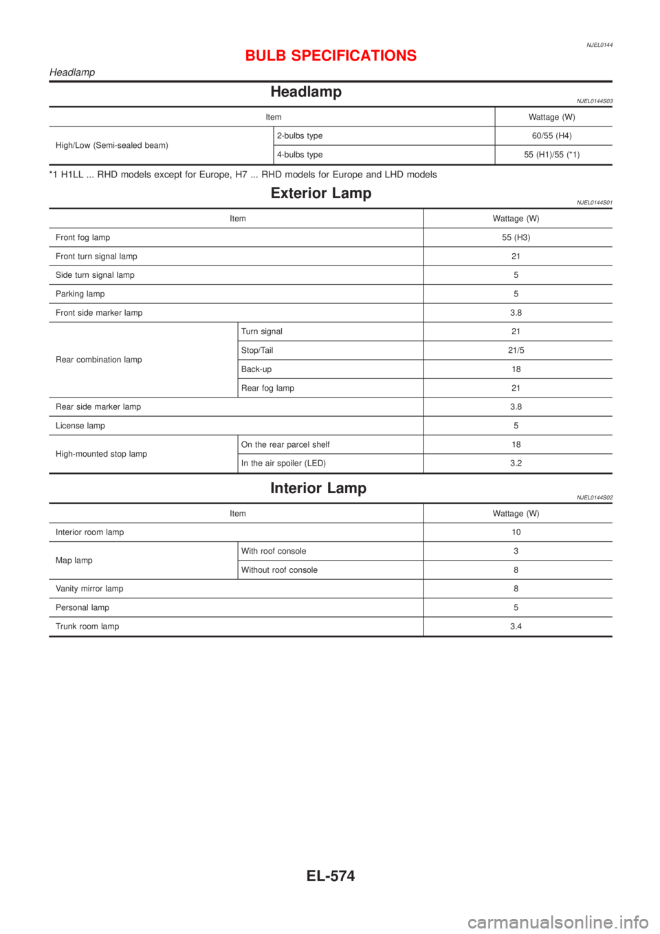
NJEL0144
HeadlampNJEL0144S03
Item Wattage (W)
High/Low (Semi-sealed beam)2-bulbs type 60/55 (H4)
4-bulbs type 55 (H1)/55 (*1)
*1 H1LL ... RHD models except for Europe, H7 ... RHD models for Europe and LHD models
Exterior LampNJEL0144S01
Item Wattage (W)
Front fog lamp55 (H3)
Front turn signal lamp21
Side turn signal lamp5
Parking lamp5
Front side marker lamp3.8
Rear combination lampTurn signal 21
Stop/Tail 21/5
Back-up 18
Rear fog lamp 21
Rear side marker lamp3.8
License lamp5
High-mounted stop lampOn the rear parcel shelf 18
In the air spoiler (LED) 3.2
Interior LampNJEL0144S02
Item Wattage (W)
Interior room lamp10
Map lampWith roof console 3
Without roof console 8
Vanity mirror lamp8
Personal lamp5
Trunk room lamp3.4
BULB SPECIFICATIONS
Headlamp
EL-574
Page 2134 of 2898
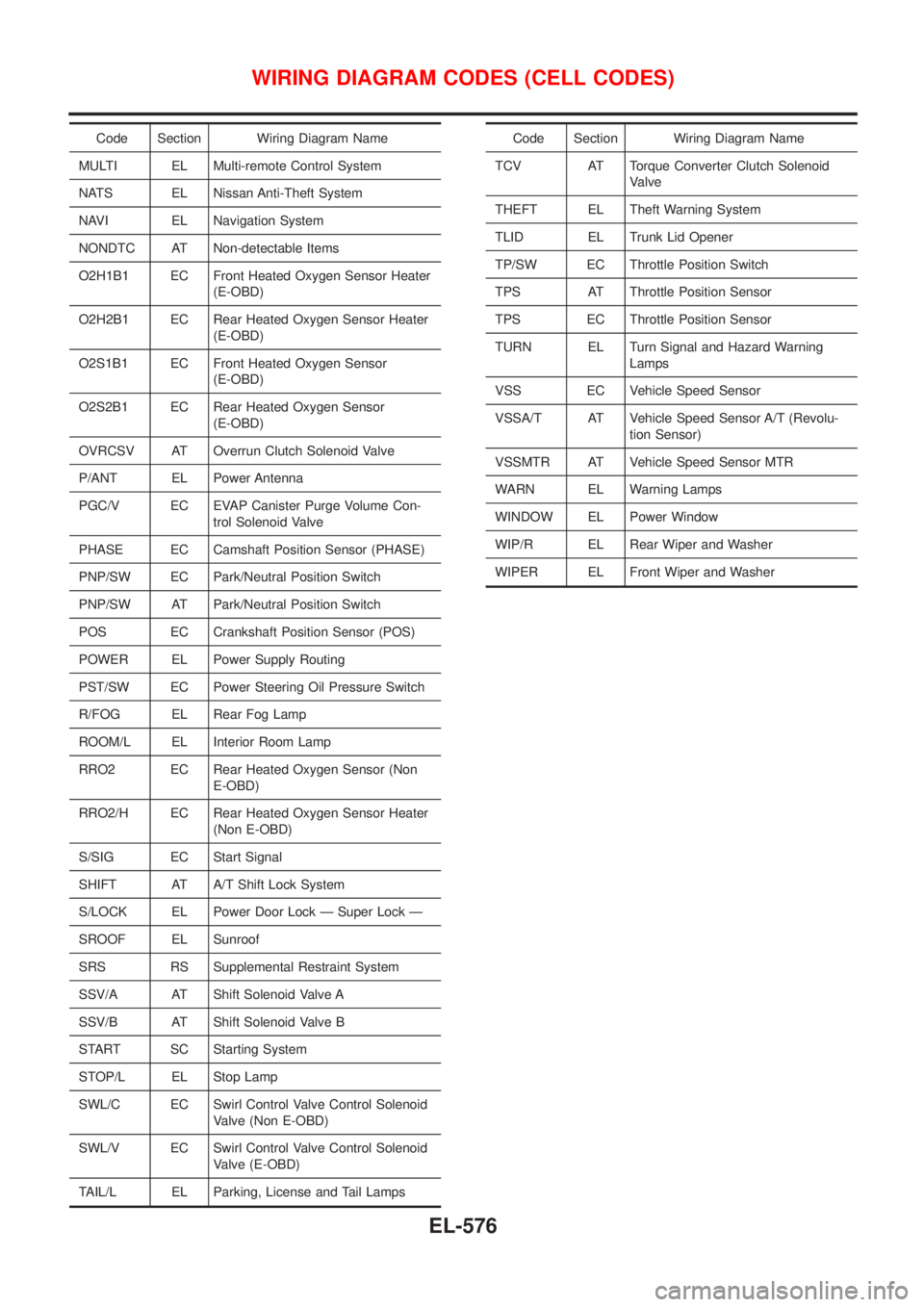
Code Section Wiring Diagram Name
MULTI EL Multi-remote Control System
NATS EL Nissan Anti-Theft System
NAVI EL Navigation System
NONDTC AT Non-detectable Items
O2H1B1 EC Front Heated Oxygen Sensor Heater
(E-OBD)
O2H2B1 EC Rear Heated Oxygen Sensor Heater
(E-OBD)
O2S1B1 EC Front Heated Oxygen Sensor
(E-OBD)
O2S2B1 EC Rear Heated Oxygen Sensor
(E-OBD)
OVRCSV AT Overrun Clutch Solenoid Valve
P/ANT EL Power Antenna
PGC/V EC EVAP Canister Purge Volume Con-
trol Solenoid Valve
PHASE EC Camshaft Position Sensor (PHASE)
PNP/SW EC Park/Neutral Position Switch
PNP/SW AT Park/Neutral Position Switch
POS EC Crankshaft Position Sensor (POS)
POWER EL Power Supply Routing
PST/SW EC Power Steering Oil Pressure Switch
R/FOG EL Rear Fog Lamp
ROOM/L EL Interior Room Lamp
RRO2 EC Rear Heated Oxygen Sensor (Non
E-OBD)
RRO2/H EC Rear Heated Oxygen Sensor Heater
(Non E-OBD)
S/SIG EC Start Signal
SHIFT AT A/T Shift Lock System
S/LOCK EL Power Door Lock Ð Super Lock Ð
SROOF EL Sunroof
SRS RS Supplemental Restraint System
SSV/A AT Shift Solenoid Valve A
SSV/B AT Shift Solenoid Valve B
START SC Starting System
STOP/L EL Stop Lamp
SWL/C EC Swirl Control Valve Control Solenoid
Valve (Non E-OBD)
SWL/V EC Swirl Control Valve Control Solenoid
Valve (E-OBD)
TAIL/L EL Parking, License and Tail LampsCode Section Wiring Diagram Name
TCV AT Torque Converter Clutch Solenoid
Valve
THEFT EL Theft Warning System
TLID EL Trunk Lid Opener
TP/SW EC Throttle Position Switch
TPS AT Throttle Position Sensor
TPS EC Throttle Position Sensor
TURN EL Turn Signal and Hazard Warning
Lamps
VSS EC Vehicle Speed Sensor
VSSA/T AT Vehicle Speed Sensor A/T (Revolu-
tion Sensor)
VSSMTR AT Vehicle Speed Sensor MTR
WARN EL Warning Lamps
WINDOW EL Power Window
WIP/R EL Rear Wiper and Washer
WIPER EL Front Wiper and Washer
WIRING DIAGRAM CODES (CELL CODES)
EL-576