Page 1663 of 2898
MODELS AFTER VIN NO. Ð N16U0135126NJEL0431S02
YEL348C
TURN SIGNAL AND HAZARD WARNING LAMPS
Wiring Diagram Ð TURN Ð/Hatchback (Cont'd)
EL-105
Page 1664 of 2898
YEL349C
TURN SIGNAL AND HAZARD WARNING LAMPS
Wiring Diagram Ð TURN Ð/Hatchback (Cont'd)
EL-106
Page 1665 of 2898

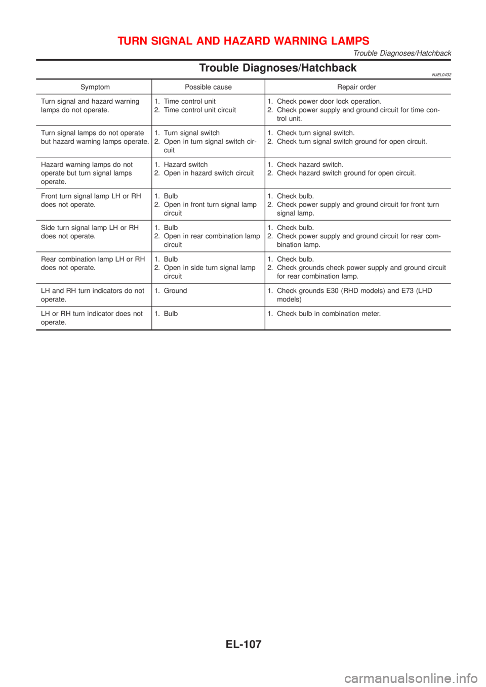
Trouble Diagnoses/HatchbackNJEL0432
Symptom Possible cause Repair order
Turn signal and hazard warning
lamps do not operate.1. Time control unit
2. Time control unit circuit1. Check power door lock operation.
2. Check power supply and ground circuit for time con-
trol unit.
Turn signal lamps do not operate
but hazard warning lamps operate.1. Turn signal switch
2. Open in turn signal switch cir-
cuit1. Check turn signal switch.
2. Check turn signal switch ground for open circuit.
Hazard warning lamps do not
operate but turn signal lamps
operate.1. Hazard switch
2. Open in hazard switch circuit1. Check hazard switch.
2. Check hazard switch ground for open circuit.
Front turn signal lamp LH or RH
does not operate.1. Bulb
2. Open in front turn signal lamp
circuit1. Check bulb.
2. Check power supply and ground circuit for front turn
signal lamp.
Side turn signal lamp LH or RH
does not operate.1. Bulb
2. Open in rear combination lamp
circuit1. Check bulb.
2. Check power supply and ground circuit for rear com-
bination lamp.
Rear combination lamp LH or RH
does not operate.1. Bulb
2. Open in side turn signal lamp
circuit1. Check bulb.
2. Check grounds check power supply and ground circuit
for rear combination lamp.
LH and RH turn indicators do not
operate.1. Ground 1. Check grounds E30 (RHD models) and E73 (LHD
models)
LH or RH turn indicator does not
operate.1. Bulb 1. Check bulb in combination meter.
TURN SIGNAL AND HAZARD WARNING LAMPS
Trouble Diagnoses/Hatchback
EL-107
Page 1686 of 2898
+driver's door is locked,
+driver's door is opened, or
+ignition switch is turned ON.
ON-OFF CONTROLNJEL0435S04When the driver side door, front passenger door, rear LH or RH door is opened, the interior room lamp turns
on while the interior room lamp switch is in the ªDOORº position.
BATTERY SAVERNJEL0435S11The interior room lamp is turned OFF automatically with the lamp switch in the ªDOORº position after about
30 minutes, if the lamp remains lit by the door switch open signal.
INTERIOR ROOM LAMP
System Description/Hatchback With Interior Room Lamp Timer (Cont'd)
EL-128
Page 1721 of 2898
MEL424F
THERMAL TRANSMITTER CHECKNJEL0047S02Check the resistance between the terminals of thermal transmitter
and body ground.
Water temperature Resistance
60ÉC (140ÉF) Approx. 170 - 210W
100ÉC (212ÉF) Approx. 47 - 53W
CEL219AA
VEHICLE SPEED SENSOR SIGNAL CHECKNJEL0047S031. Remove vehicle speed sensor from transmission.
2. Turn vehicle speed sensor pinion quickly and measure voltage
across 1 and 2.
METERS AND GAUGES
Electrical Components Inspection/Sedan (Cont'd)
EL-163
Page 1733 of 2898

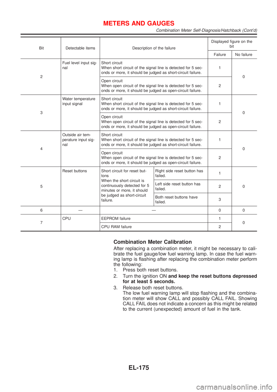
Bit Detectable items Description of the failureDisplayed figure on the
bit
Failure No failure
2Fuel level input sig-
nalShort circuit
When short circuit of the signal line is detected for 5 sec-
onds or more, it should be judged as short-circuit failure.1
0
Open circuit
When open circuit of the signal line is detected for 5 sec-
onds or more, it should be judged as open-circuit failure.2
3Water temperature
input signalShort circuit
When short circuit of the signal line is detected for 5 sec-
onds or more, it should be judged as short-circuit failure.1
0
Open circuit
When open circuit of the signal line is detected for 5 sec-
onds or more, it should be judged as open-circuit failure.2
4Outside air tem-
perature input sig-
nalShort circuit
When short circuit of the signal line is detected for 5 sec-
onds or more, it should be judged as short-circuit failure.1
0
Open circuit
When open circuit of the signal line is detected for 5 sec-
onds or more, it should be judged as open-circuit failure.2
5Reset buttons Short circuit for reset but-
tons
When the short circuit is
continuously detected for 5
minutes or more, it should
be judged as short-circuit
failure.Right side reset button has
failed.1
0 Left side reset button has
failed.2
Both reset buttons have
failed.3
6Ð Ð 00
7CPU EEPROM failure 1
0
CPU RAM failure 2
Combination Meter Calibration
After replacing a combination meter, it might be necessary to cali-
brate the fuel gauge/low fuel warning lamp. In case the fuel warn-
ing lamp is flashing after replacing the combination meter perform
the following:
1. Press both reset buttons.
2. Turn the ignition ONand keep the reset buttons depressed
for at least 5 seconds.
3. Release both reset buttons.
The low fuel warning lamp will stop flashing and the combina-
tion meter will show CALL and possibly CALL FAIL. Showing
CALL FAIL does not indicate a concern as this might be related
to the current (unexpected) amount of fuel in the tank.
METERS AND GAUGES
Combination Meter Self-Diagnosis/Hatchback (Cont'd)
EL-175
Page 1741 of 2898
SEL498X
Electrical Components Inspection/Hatchback=NJEL0449FUEL LEVEL SENSOR UNIT CHECKNJEL0449S02+For removal, refer to FE-6, FE-23, ªFUEL SYSTEMº.
Check the resistance between terminals 4 and 1.
Ohmmeter
Float position mm (in)Resistance
valueW
(+) (þ)
41*1 Full 142.5 (5.61) Approx.4-6
*2 1/2 88.7 (3.492) 32 - 33
*3 Empty 11.1 (0.437) 80 - 83
*1 and *3: When float rod is in contact with stopper.
MEL424F
THERMAL TRANSMITTER CHECKNJEL0449S03Check the resistance between the terminals of thermal transmitter
and body ground.
Water temperature Resistance
65ÉC (149ÉF) Approx. 1,179 - 1,417W
91ÉC (196ÉF) Approx. 474 - 568W
CEL219AA
VEHICLE SPEED SENSOR SIGNAL CHECKNJEL0449S041. Remove vehicle speed sensor from transmission.
2. Turn vehicle speed sensor pinion quickly and measure voltage
across 1 and 2.
METERS AND GAUGES
Electrical Components Inspection/Hatchback
EL-183
Page 1804 of 2898

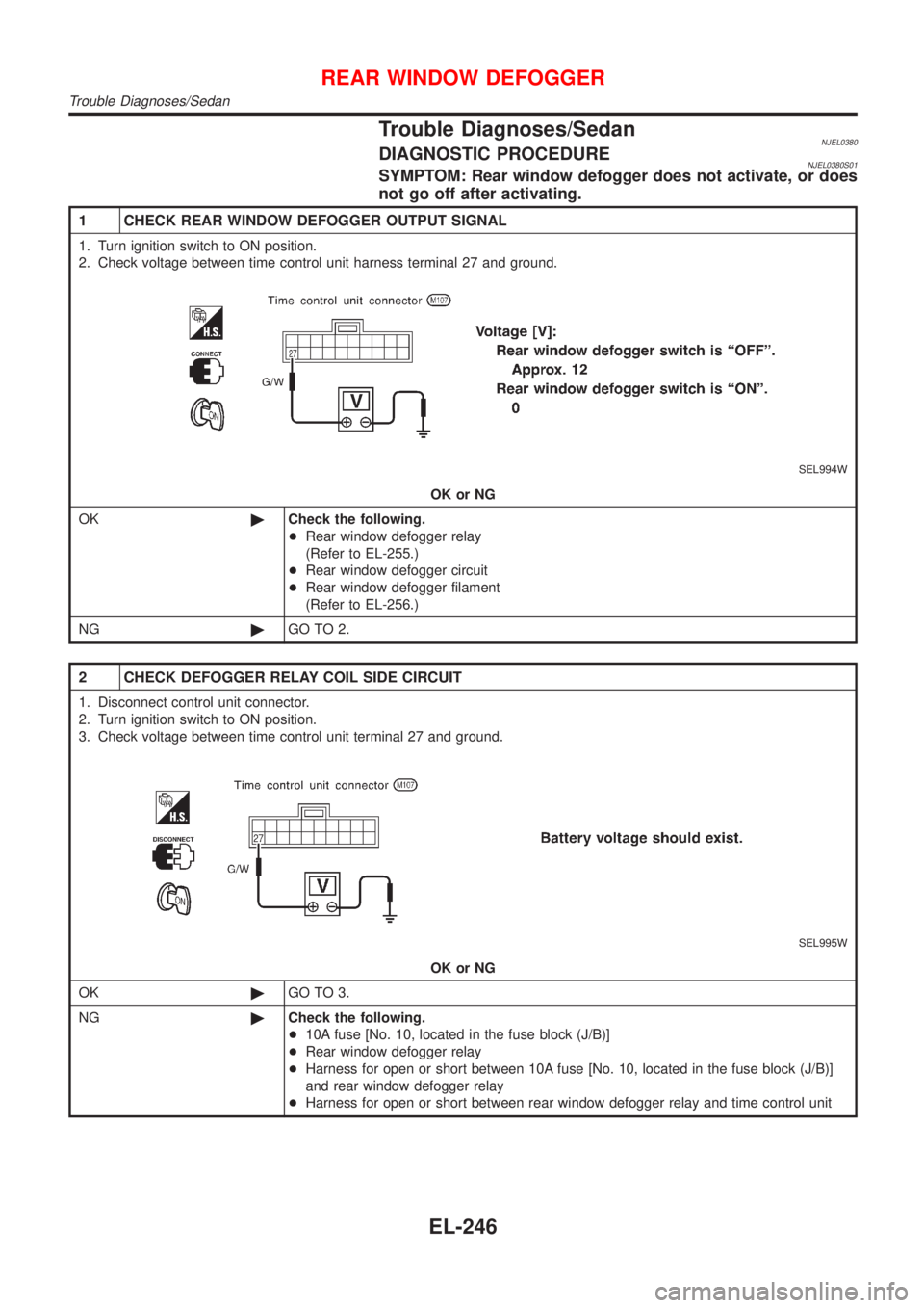
Trouble Diagnoses/SedanNJEL0380DIAGNOSTIC PROCEDURENJEL0380S01SYMPTOM: Rear window defogger does not activate, or does
not go off after activating.
1 CHECK REAR WINDOW DEFOGGER OUTPUT SIGNAL
1. Turn ignition switch to ON position.
2. Check voltage between time control unit harness terminal 27 and ground.
SEL994W
OK or NG
OK©Check the following.
+Rear window defogger relay
(Refer to EL-255.)
+Rear window defogger circuit
+Rear window defogger filament
(Refer to EL-256.)
NG©GO TO 2.
2 CHECK DEFOGGER RELAY COIL SIDE CIRCUIT
1. Disconnect control unit connector.
2. Turn ignition switch to ON position.
3. Check voltage between time control unit terminal 27 and ground.
SEL995W
OK or NG
OK©GO TO 3.
NG©Check the following.
+10A fuse [No. 10, located in the fuse block (J/B)]
+Rear window defogger relay
+Harness for open or short between 10A fuse [No. 10, located in the fuse block (J/B)]
and rear window defogger relay
+Harness for open or short between rear window defogger relay and time control unit
REAR WINDOW DEFOGGER
Trouble Diagnoses/Sedan
EL-246