Page 1160 of 2898
Diagnostic ProcedureNJEC0578
1 CHECK INPUT SIGNAL CIRCUIT
1. Turn ignition switch ªOFFº.
2. Disconnect ECM harness connector and TCM harness connector.
SEF116Y
3. Check harness continuity between ECM terminal 91 and TCM terminal 15.
Refer to Wiring Diagram.
Continuity should exist.
4. Also check harness for short to ground and short to power.
OK or NG
OK©GO TO 2.
NG©Repair open circuit or short to ground or short to power in harness or connectors.
2 CHECK INTERMITTENT INCIDENT
Perform ªTROUBLE DIAGNOSIS FOR INTERMITTENT INCIDENTº, EC-177.
©INSPECTION END
DTC P1605 A/T DIAGNOSIS COMMUNICATION LINEQG
Diagnostic Procedure
EC-436
Page 1163 of 2898
Wiring DiagramNJEC0430
HEC808
DTC P1706 PARK/NEUTRAL POSITION (PNP) SWITCHQG
Wiring Diagram
EC-439
Page 1164 of 2898

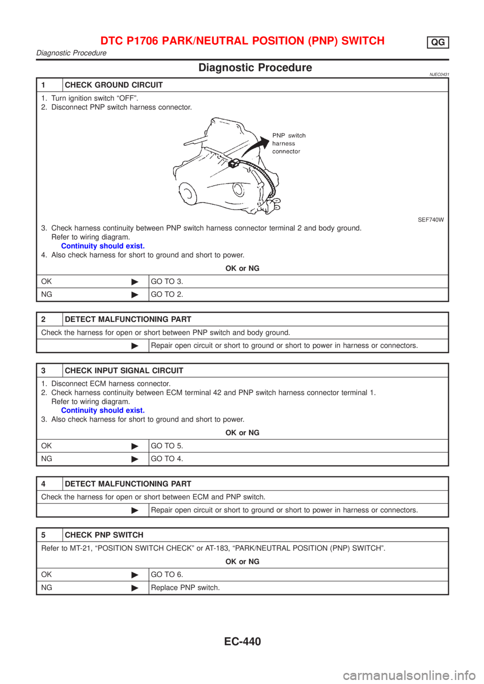
Diagnostic ProcedureNJEC0431
1 CHECK GROUND CIRCUIT
1. Turn ignition switch ªOFFº.
2. Disconnect PNP switch harness connector.
SEF740W
3. Check harness continuity between PNP switch harness connector terminal 2 and body ground.
Refer to wiring diagram.
Continuity should exist.
4. Also check harness for short to ground and short to power.
OK or NG
OK©GO TO 3.
NG©GO TO 2.
2 DETECT MALFUNCTIONING PART
Check the harness for open or short between PNP switch and body ground.
©Repair open circuit or short to ground or short to power in harness or connectors.
3 CHECK INPUT SIGNAL CIRCUIT
1. Disconnect ECM harness connector.
2. Check harness continuity between ECM terminal 42 and PNP switch harness connector terminal 1.
Refer to wiring diagram.
Continuity should exist.
3. Also check harness for short to ground and short to power.
OK or NG
OK©GO TO 5.
NG©GO TO 4.
4 DETECT MALFUNCTIONING PART
Check the harness for open or short between ECM and PNP switch.
©Repair open circuit or short to ground or short to power in harness or connectors.
5 CHECK PNP SWITCH
Refer to MT-21, ªPOSITION SWITCH CHECKº or AT-183, ªPARK/NEUTRAL POSITION (PNP) SWITCHº.
OK or NG
OK©GO TO 6.
NG©Replace PNP switch.
DTC P1706 PARK/NEUTRAL POSITION (PNP) SWITCHQG
Diagnostic Procedure
EC-440
Page 1168 of 2898
Wiring DiagramNJEC1738MODELS WITH INTAKE AIR TEMPERATURE SENSOR
IN MASS AIR FLOW SENSOR
NJEC1738S01
HEC948
INTAKE AIR TEMPERATURE SENSORQG
Wiring Diagram
EC-444
Page 1169 of 2898
MODELS WITH INTAKE AIR TEMPERATURE SENSOR
ON INTAKE AIR DUCT
NJEC1738S02
NEF330A
INTAKE AIR TEMPERATURE SENSORQG
Wiring Diagram (Cont'd)
EC-445
Page 1171 of 2898

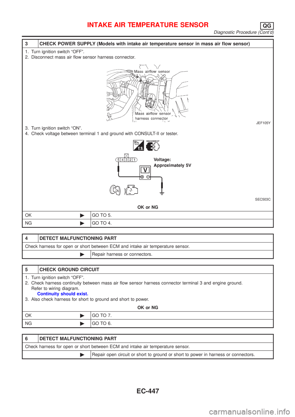
3 CHECK POWER SUPPLY (Models with intake air temperature sensor in mass air flow sensor)
1. Turn ignition switch ªOFFº.
2. Disconnect mass air flow sensor harness connector.
JEF105Y
3. Turn ignition switch ªONº.
4. Check voltage between terminal 1 and ground with CONSULT-II or tester.
SEC503C
OK or NG
OK©GO TO 5.
NG©GO TO 4.
4 DETECT MALFUNCTIONING PART
Check harness for open or short between ECM and intake air temperature sensor.
©Repair harness or connectors.
5 CHECK GROUND CIRCUIT
1. Turn ignition switch ªOFFº.
2. Check harness continuity between mass air flow sensor harness connector terminal 3 and engine ground.
Refer to wiring diagram.
Continuity should exist.
3. Also check harness for short to ground and short to power.
OK or NG
OK©GO TO 7.
NG©GO TO 6.
6 DETECT MALFUNCTIONING PART
Check harness for open or short between ECM and intake air temperature sensor.
©Repair open circuit or short to ground or short to power in harness or connectors.
INTAKE AIR TEMPERATURE SENSORQG
Diagnostic Procedure (Cont'd)
EC-447
Page 1175 of 2898
Wiring DiagramNJEC1220SEDAN MODELS AND HATCHBACK MODELS WITH
ECM IN ENGINE COMPARTMENT
NJEC1220S03
HEC851
HEATED OXYGEN SENSOR 1 (FRONT)QG
Wiring Diagram
EC-451
Page 1176 of 2898
HATCHBACK MODELS WITH ECM IN CABINNJEC1220S04
HEC937
HEATED OXYGEN SENSOR 1 (FRONT)QG
Wiring Diagram (Cont'd)
EC-452