Page 1194 of 2898
Wiring DiagramNJEC1245SEDAN MODELS AND HATCHBACK MODELS WITH
ECM IN ENGINE COMPARTMENT
NJEC1245S03
HEC854
HEATED OXYGEN SENSOR 2 HEATER (REAR)QG
Wiring Diagram
EC-470
Page 1195 of 2898
HATCHBACK MODELS WITH ECM IN CABINNJEC1245S04
HEC943
HEATED OXYGEN SENSOR 2 HEATER (REAR)QG
Wiring Diagram (Cont'd)
EC-471
Page 1197 of 2898

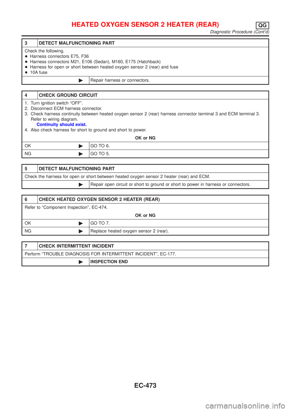
3 DETECT MALFUNCTIONING PART
Check the following.
+Harness connectors E75, F36
+Harness connectors M21, E106 (Sedan), M160, E175 (Hatchback)
+Harness for open or short between heated oxygen sensor 2 (rear) and fuse
+10A fuse
©Repair harness or connectors.
4 CHECK GROUND CIRCUIT
1. Turn ignition switch ªOFFº.
2. Disconnect ECM harness connector.
3. Check harness continuity between heated oxygen sensor 2 (rear) harness connector terminal 3 and ECM terminal 3.
Refer to wiring diagram.
Continuity should exist.
4. Also check harness for short to ground and short to power.
OK or NG
OK©GO TO 6.
NG©GO TO 5.
5 DETECT MALFUNCTIONING PART
Check the harness for open or short between heated oxygen sensor 2 heater (rear) and ECM.
©Repair open circuit or short to ground or short to power in harness or connectors.
6 CHECK HEATED OXYGEN SENSOR 2 HEATER (REAR)
Refer to ªComponent Inspectionº, EC-474.
OK or NG
OK©GO TO 7.
NG©Replace heated oxygen sensor 2 (rear).
7 CHECK INTERMITTENT INCIDENT
Perform ªTROUBLE DIAGNOSIS FOR INTERMITTENT INCIDENTº, EC-177.
©INSPECTION END
HEATED OXYGEN SENSOR 2 HEATER (REAR)QG
Diagnostic Procedure (Cont'd)
EC-473
Page 1201 of 2898
Wiring DiagramNJEC1254
HEC855
SWIRL CONTROL VALVE CONTROL SYSTEM (WHERE FITTED)QG
Wiring Diagram
EC-477
Page 1205 of 2898

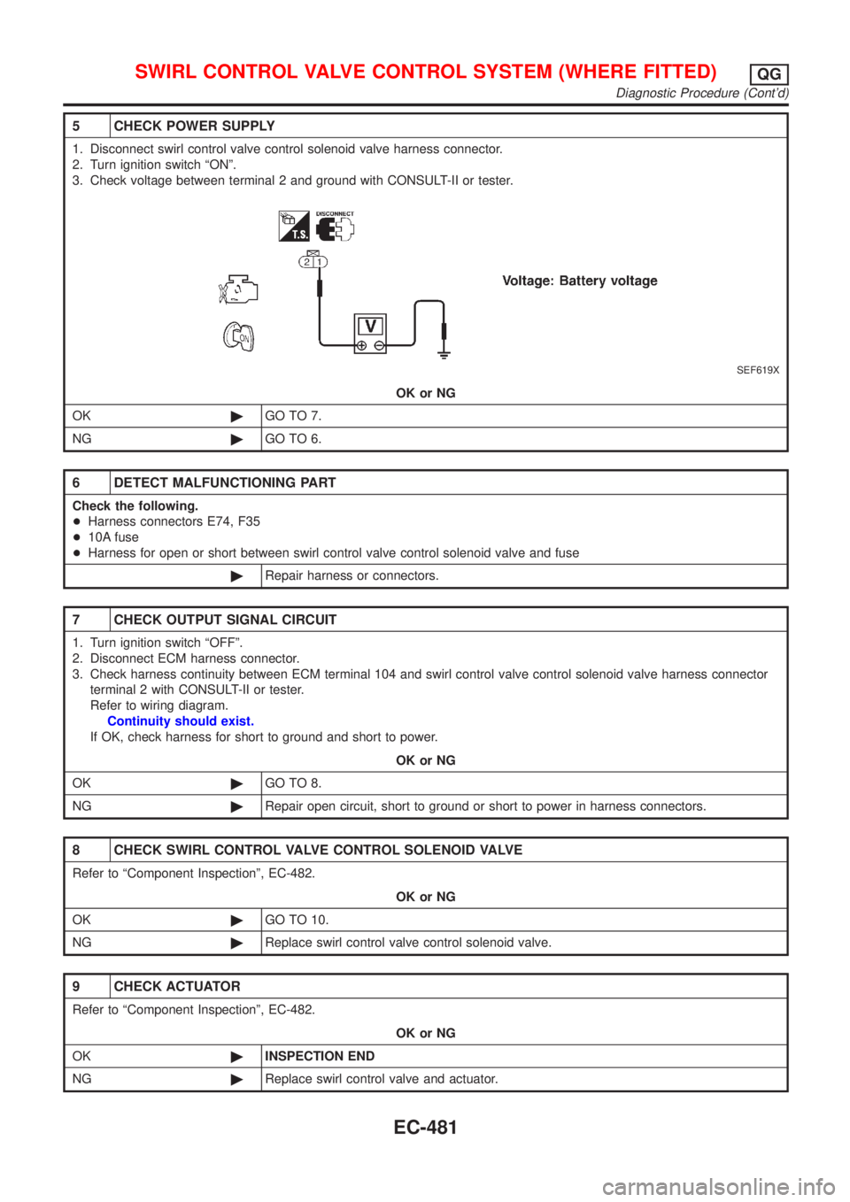
5 CHECK POWER SUPPLY
1. Disconnect swirl control valve control solenoid valve harness connector.
2. Turn ignition switch ªONº.
3. Check voltage between terminal 2 and ground with CONSULT-II or tester.
SEF619X
OK or NG
OK©GO TO 7.
NG©GO TO 6.
6 DETECT MALFUNCTIONING PART
Check the following.
+Harness connectors E74, F35
+10A fuse
+Harness for open or short between swirl control valve control solenoid valve and fuse
©Repair harness or connectors.
7 CHECK OUTPUT SIGNAL CIRCUIT
1. Turn ignition switch ªOFFº.
2. Disconnect ECM harness connector.
3. Check harness continuity between ECM terminal 104 and swirl control valve control solenoid valve harness connector
terminal 2 with CONSULT-II or tester.
Refer to wiring diagram.
Continuity should exist.
If OK, check harness for short to ground and short to power.
OK or NG
OK©GO TO 8.
NG©Repair open circuit, short to ground or short to power in harness connectors.
8 CHECK SWIRL CONTROL VALVE CONTROL SOLENOID VALVE
Refer to ªComponent Inspectionº, EC-482.
OK or NG
OK©GO TO 10.
NG©Replace swirl control valve control solenoid valve.
9 CHECK ACTUATOR
Refer to ªComponent Inspectionº, EC-482.
OK or NG
OK©INSPECTION END
NG©Replace swirl control valve and actuator.
SWIRL CONTROL VALVE CONTROL SYSTEM (WHERE FITTED)QG
Diagnostic Procedure (Cont'd)
EC-481
Page 1209 of 2898
Wiring DiagramNJEC1743SEDAN MODELS AND HATCHBACK MODELS WITH ECM IN ENGINE COMPARTMENTNJEC1743S01
NEF331A
CRANKSHAFT POSITION SENSOR (POS)QG
Wiring Diagram
EC-485
Page 1210 of 2898
HATCHBACK MODELS WITH ECM IN CABINNJEC1743S02
HEC981
CRANKSHAFT POSITION SENSOR (POS)QG
Wiring Diagram (Cont'd)
EC-486
Page 1213 of 2898

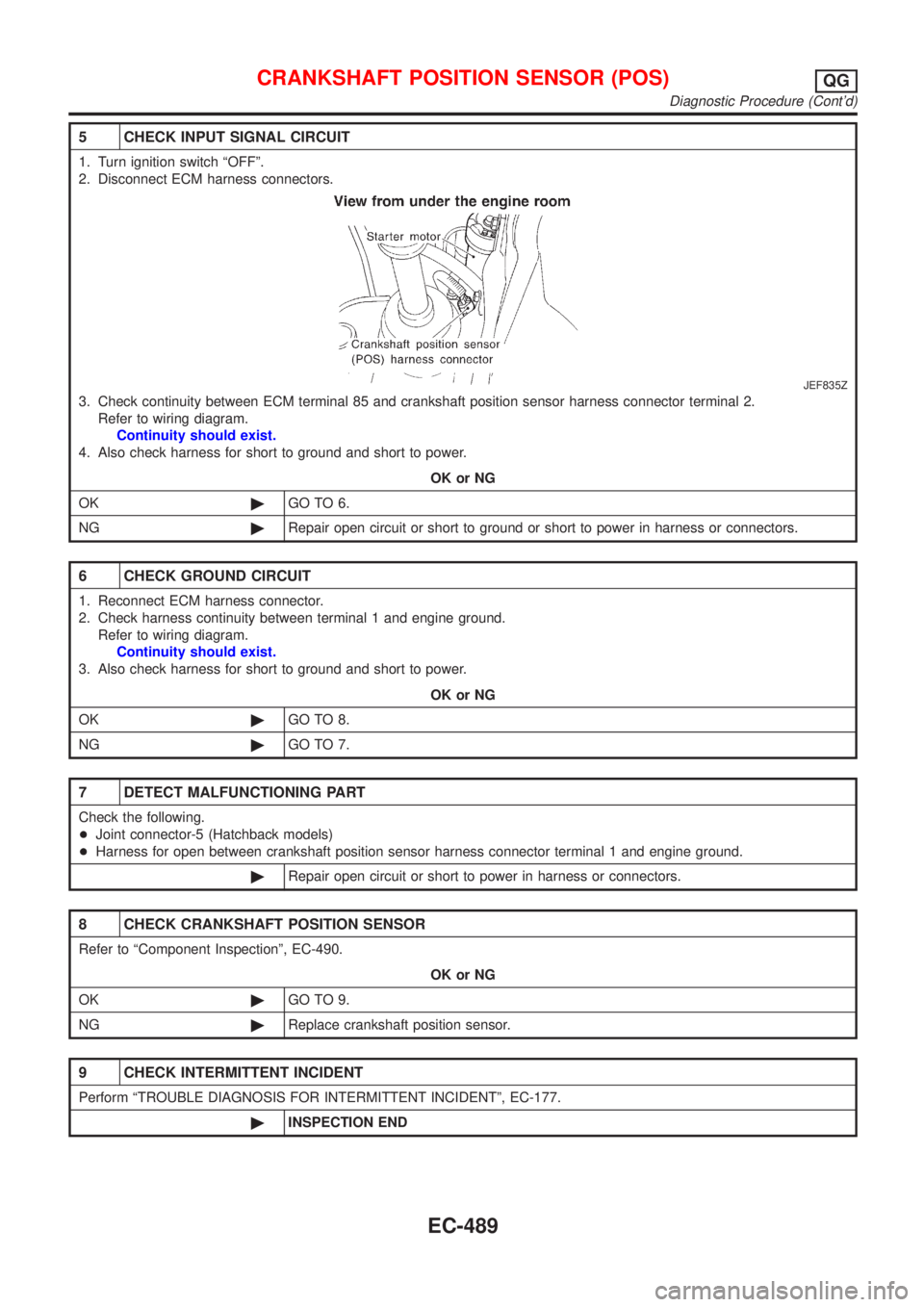
5 CHECK INPUT SIGNAL CIRCUIT
1. Turn ignition switch ªOFFº.
2. Disconnect ECM harness connectors.
JEF835Z
3. Check continuity between ECM terminal 85 and crankshaft position sensor harness connector terminal 2.
Refer to wiring diagram.
Continuity should exist.
4. Also check harness for short to ground and short to power.
OK or NG
OK©GO TO 6.
NG©Repair open circuit or short to ground or short to power in harness or connectors.
6 CHECK GROUND CIRCUIT
1. Reconnect ECM harness connector.
2. Check harness continuity between terminal 1 and engine ground.
Refer to wiring diagram.
Continuity should exist.
3. Also check harness for short to ground and short to power.
OK or NG
OK©GO TO 8.
NG©GO TO 7.
7 DETECT MALFUNCTIONING PART
Check the following.
+Joint connector-5 (Hatchback models)
+Harness for open between crankshaft position sensor harness connector terminal 1 and engine ground.
©Repair open circuit or short to power in harness or connectors.
8 CHECK CRANKSHAFT POSITION SENSOR
Refer to ªComponent Inspectionº, EC-490.
OK or NG
OK©GO TO 9.
NG©Replace crankshaft position sensor.
9 CHECK INTERMITTENT INCIDENT
Perform ªTROUBLE DIAGNOSIS FOR INTERMITTENT INCIDENTº, EC-177.
©INSPECTION END
CRANKSHAFT POSITION SENSOR (POS)QG
Diagnostic Procedure (Cont'd)
EC-489