Page 1218 of 2898
Wiring DiagramNJEC1749SEDAN MODELS AND HATCHBACK MODELS WITH ECM IN ENGINE COMPARTMENTNJEC1749S01
HEC794
EGR VOLUME CONTROL SYSTEM (WHERE FITTED)QG
Wiring Diagram
EC-494
Page 1219 of 2898
HATCHBACK MODELS WITH ECM IN CABINNJEC1749S02
HEC976
EGR VOLUME CONTROL SYSTEM (WHERE FITTED)QG
Wiring Diagram (Cont'd)
EC-495
Page 1223 of 2898

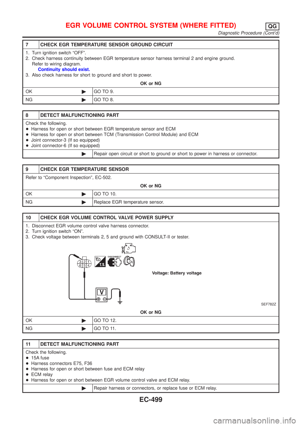
7 CHECK EGR TEMPERATURE SENSOR GROUND CIRCUIT
1. Turn ignition switch ªOFFº.
2. Check harness continuity between EGR temperature sensor harness terminal 2 and engine ground.
Refer to wiring diagram.
Continuity should exist.
3. Also check harness for short to ground and short to power.
OK or NG
OK©GO TO 9.
NG©GO TO 8.
8 DETECT MALFUNCTIONING PART
Check the following.
+Harness for open or short between EGR temperature sensor and ECM
+Harness for open or short between TCM (Transmission Control Module) and ECM
+Joint connector-3 (If so equipped)
+Joint connector-6 (If so equipped)
©Repair open circuit or short to ground or short to power in harness or connector.
9 CHECK EGR TEMPERATURE SENSOR
Refer to ªComponent Inspectionº, EC-502.
OK or NG
OK©GO TO 10.
NG©Replace EGR temperature sensor.
10 CHECK EGR VOLUME CONTROL VALVE POWER SUPPLY
1. Disconnect EGR volume control valve harness connector.
2. Turn ignition switch ªONº.
3. Check voltage between terminals 2, 5 and ground with CONSULT-II or tester.
SEF782Z
OK or NG
OK©GO TO 12.
NG©GO TO 11.
11 DETECT MALFUNCTIONING PART
Check the following.
+15A fuse
+Harness connectors E75, F36
+Harness for open or short between fuse and ECM relay
+ECM relay
+Harness for open or short between EGR volume control valve and ECM relay.
©Repair harness or connectors, or replace fuse or ECM relay.
EGR VOLUME CONTROL SYSTEM (WHERE FITTED)QG
Diagnostic Procedure (Cont'd)
EC-499
Page 1224 of 2898

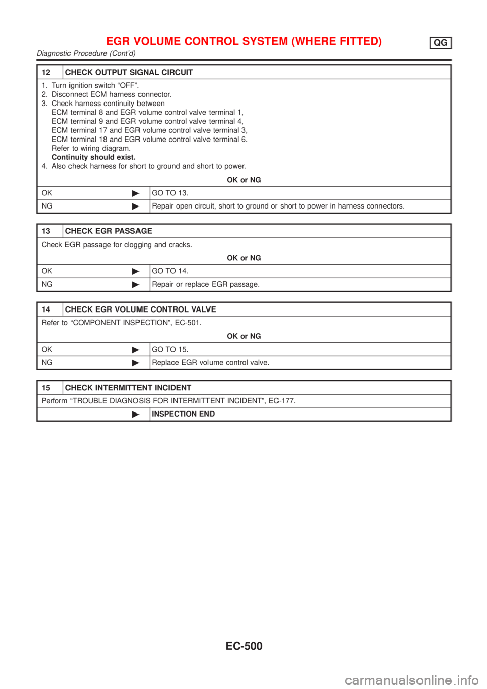
12 CHECK OUTPUT SIGNAL CIRCUIT
1. Turn ignition switch ªOFFº.
2. Disconnect ECM harness connector.
3. Check harness continuity between
ECM terminal 8 and EGR volume control valve terminal 1,
ECM terminal 9 and EGR volume control valve terminal 4,
ECM terminal 17 and EGR volume control valve terminal 3,
ECM terminal 18 and EGR volume control valve terminal 6.
Refer to wiring diagram.
Continuity should exist.
4. Also check harness for short to ground and short to power.
OK or NG
OK©GO TO 13.
NG©Repair open circuit, short to ground or short to power in harness connectors.
13 CHECK EGR PASSAGE
Check EGR passage for clogging and cracks.
OK or NG
OK©GO TO 14.
NG©Repair or replace EGR passage.
14 CHECK EGR VOLUME CONTROL VALVE
Refer to ªCOMPONENT INSPECTIONº, EC-501.
OK or NG
OK©GO TO 15.
NG©Replace EGR volume control valve.
15 CHECK INTERMITTENT INCIDENT
Perform ªTROUBLE DIAGNOSIS FOR INTERMITTENT INCIDENTº, EC-177.
©INSPECTION END
EGR VOLUME CONTROL SYSTEM (WHERE FITTED)QG
Diagnostic Procedure (Cont'd)
EC-500
Page 1229 of 2898
Wiring DiagramNJEC1755HATCHBACK MODELS WITH ECM IN CABINNJEC1755S01
HEC969
EVAP CANISTER PURGE VOLUME CONTROL SOLENOID VALVEQG
Wiring Diagram
EC-505
Page 1230 of 2898
SEDAN MODELS AND HATCHBACK MODELS WITH
ECM IN ENGINE COMPARTMENT
NJEC1755S02
NEF332A
EVAP CANISTER PURGE VOLUME CONTROL SOLENOID VALVEQG
Wiring Diagram (Cont'd)
EC-506
Page 1233 of 2898

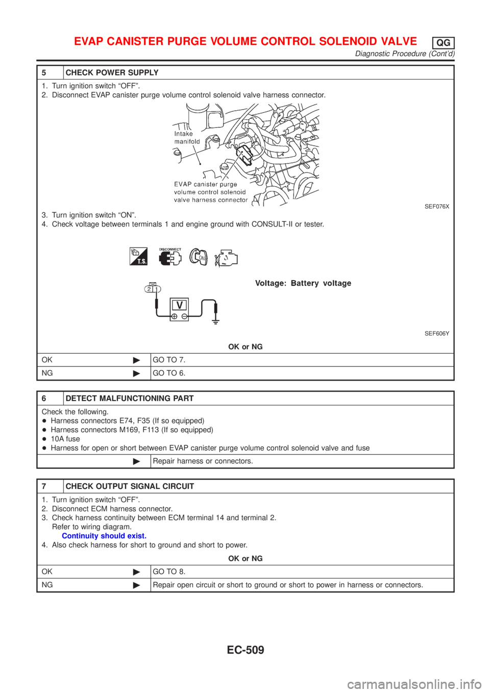
5 CHECK POWER SUPPLY
1. Turn ignition switch ªOFFº.
2. Disconnect EVAP canister purge volume control solenoid valve harness connector.
SEF076X
3. Turn ignition switch ªONº.
4. Check voltage between terminals 1 and engine ground with CONSULT-II or tester.
SEF606Y
OK or NG
OK©GO TO 7.
NG©GO TO 6.
6 DETECT MALFUNCTIONING PART
Check the following.
+Harness connectors E74, F35 (If so equipped)
+Harness connectors M169, F113 (If so equipped)
+10A fuse
+Harness for open or short between EVAP canister purge volume control solenoid valve and fuse
©Repair harness or connectors.
7 CHECK OUTPUT SIGNAL CIRCUIT
1. Turn ignition switch ªOFFº.
2. Disconnect ECM harness connector.
3. Check harness continuity between ECM terminal 14 and terminal 2.
Refer to wiring diagram.
Continuity should exist.
4. Also check harness for short to ground and short to power.
OK or NG
OK©GO TO 8.
NG©Repair open circuit or short to ground or short to power in harness or connectors.
EVAP CANISTER PURGE VOLUME CONTROL SOLENOID VALVEQG
Diagnostic Procedure (Cont'd)
EC-509
Page 1237 of 2898
Wiring DiagramNJEC1761SEDAN MODELS AND HATCHBACK MODELS WITH ECM IN ENGINE COMPARTMENTNJEC1761S01
HEC910
IDLE AIR CONTROL VALVE (IACV) Ð AUXILIARY AIR CONTROL
(AAC) VALVE
QG
Wiring Diagram
EC-513