Page 1074 of 2898

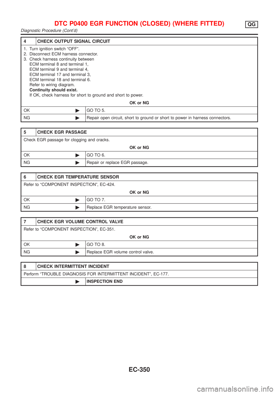
4 CHECK OUTPUT SIGNAL CIRCUIT
1. Turn ignition switch ªOFFº.
2. Disconnect ECM harness connector.
3. Check harness continuity between
ECM terminal 8 and terminal 1,
ECM terminal 9 and terminal 4,
ECM terminal 17 and terminal 3,
ECM terminal 18 and terminal 6.
Refer to wiring diagram.
Continuity should exist.
If OK, check harness for short to ground and short to power.
OK or NG
OK©GO TO 5.
NG©Repair open circuit, short to ground or short to power in harness connectors.
5 CHECK EGR PASSAGE
Check EGR passage for clogging and cracks.
OK or NG
OK©GO TO 6.
NG©Repair or replace EGR passage.
6 CHECK EGR TEMPERATURE SENSOR
Refer to ªCOMPONENT INSPECTIONº, EC-424.
OK or NG
OK©GO TO 7.
NG©Replace EGR temperature sensor.
7 CHECK EGR VOLUME CONTROL VALVE
Refer to ªCOMPONENT INSPECTIONº, EC-351.
OK or NG
OK©GO TO 8.
NG©Replace EGR volume control valve.
8 CHECK INTERMITTENT INCIDENT
Perform ªTROUBLE DIAGNOSIS FOR INTERMITTENT INCIDENTº, EC-177.
©INSPECTION END
DTC P0400 EGR FUNCTION (CLOSED) (WHERE FITTED)QG
Diagnostic Procedure (Cont'd)
EC-350
Page 1079 of 2898
Wiring DiagramNJEC0510SEDAN MODELS AND HATCHBACK MODELS WITH
ECM IN ENGINE COMPARTMENT
NJEC0510S01
HEC795
DTC P0403 EGR VOLUME CONTROL VALVE (CIRCUIT)
(WHERE FITTED)
QG
Wiring Diagram
EC-355
Page 1080 of 2898
HATCHBACK MODELS WITH ECM IN CABINNJEC0510S02
HEC977
DTC P0403 EGR VOLUME CONTROL VALVE (CIRCUIT)
(WHERE FITTED)
QG
Wiring Diagram (Cont'd)
EC-356
Page 1081 of 2898

Diagnostic ProcedureNJEC0511
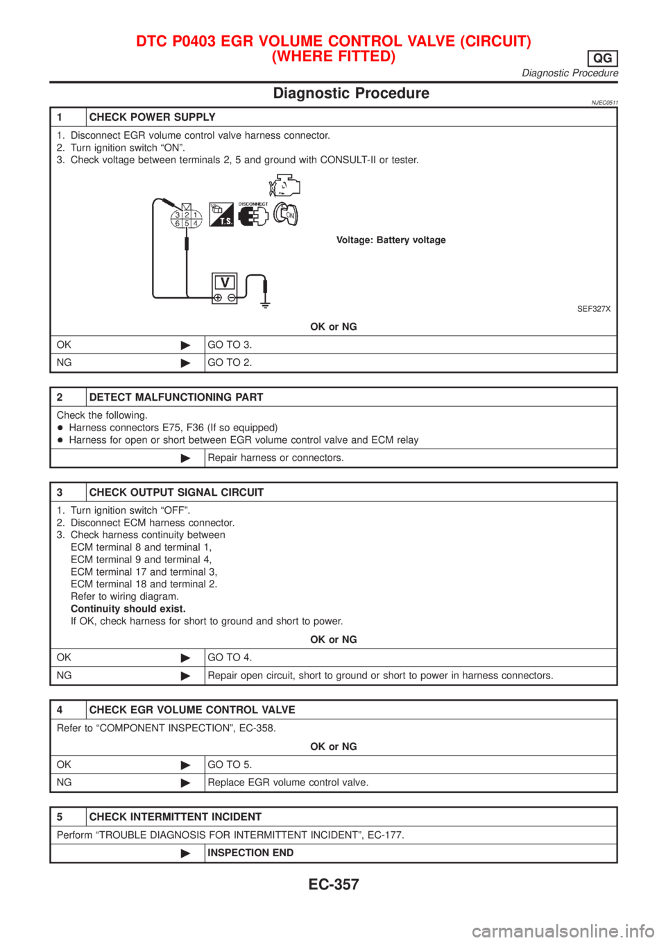
1 CHECK POWER SUPPLY
1. Disconnect EGR volume control valve harness connector.
2. Turn ignition switch ªONº.
3. Check voltage between terminals 2, 5 and ground with CONSULT-II or tester.
SEF327X
OK or NG
OK©GO TO 3.
NG©GO TO 2.
2 DETECT MALFUNCTIONING PART
Check the following.
+Harness connectors E75, F36 (If so equipped)
+Harness for open or short between EGR volume control valve and ECM relay
©Repair harness or connectors.
3 CHECK OUTPUT SIGNAL CIRCUIT
1. Turn ignition switch ªOFFº.
2. Disconnect ECM harness connector.
3. Check harness continuity between
ECM terminal 8 and terminal 1,
ECM terminal 9 and terminal 4,
ECM terminal 17 and terminal 3,
ECM terminal 18 and terminal 2.
Refer to wiring diagram.
Continuity should exist.
If OK, check harness for short to ground and short to power.
OK or NG
OK©GO TO 4.
NG©Repair open circuit, short to ground or short to power in harness connectors.
4 CHECK EGR VOLUME CONTROL VALVE
Refer to ªCOMPONENT INSPECTIONº, EC-358.
OK or NG
OK©GO TO 5.
NG©Replace EGR volume control valve.
5 CHECK INTERMITTENT INCIDENT
Perform ªTROUBLE DIAGNOSIS FOR INTERMITTENT INCIDENTº, EC-177.
©INSPECTION END
DTC P0403 EGR VOLUME CONTROL VALVE (CIRCUIT)
(WHERE FITTED)
QG
Diagnostic Procedure
EC-357
Page 1086 of 2898

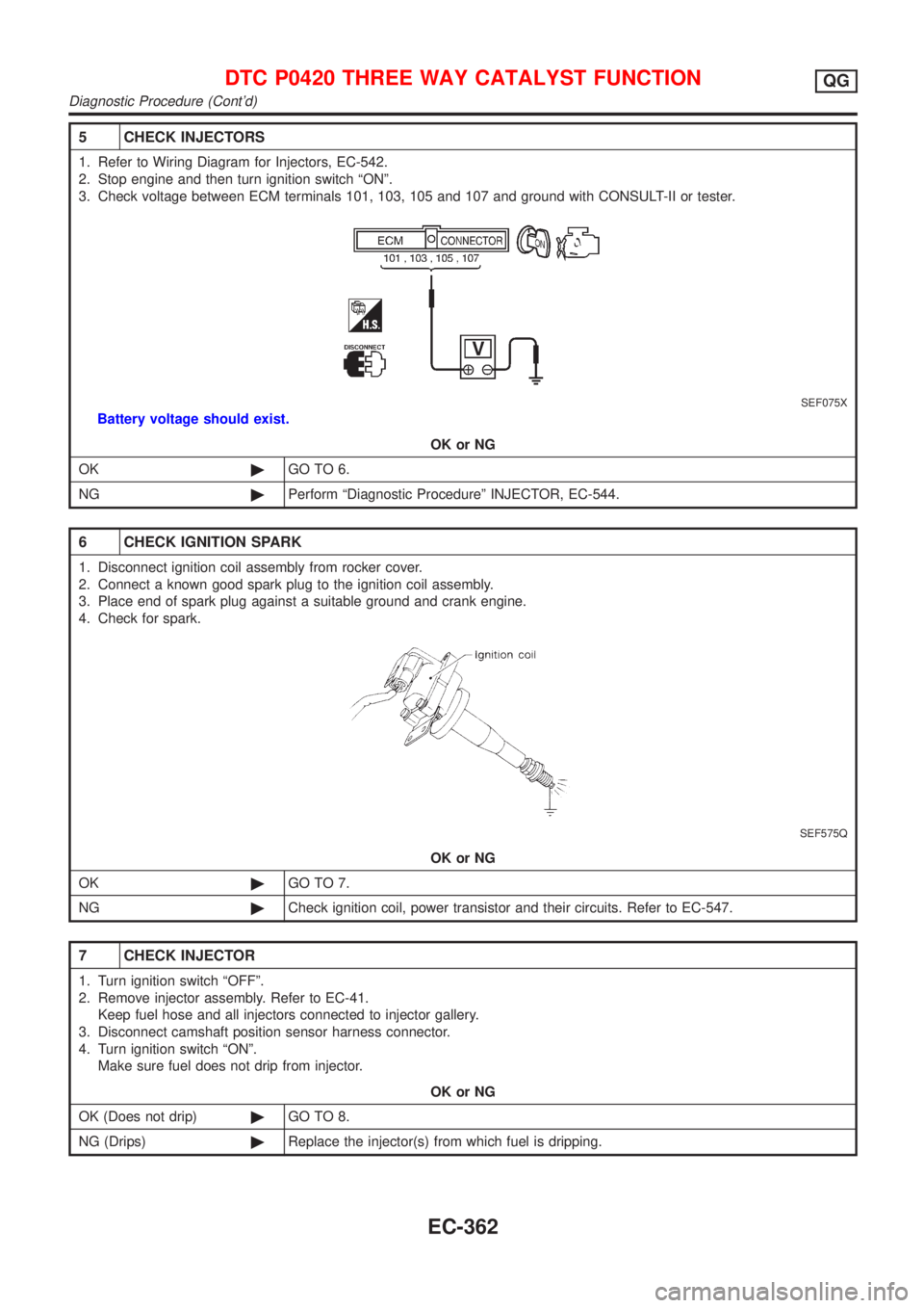
5 CHECK INJECTORS
1. Refer to Wiring Diagram for Injectors, EC-542.
2. Stop engine and then turn ignition switch ªONº.
3. Check voltage between ECM terminals 101, 103, 105 and 107 and ground with CONSULT-II or tester.
SEF075X
Battery voltage should exist.
OK or NG
OK©GO TO 6.
NG©Perform ªDiagnostic Procedureº INJECTOR, EC-544.
6 CHECK IGNITION SPARK
1. Disconnect ignition coil assembly from rocker cover.
2. Connect a known good spark plug to the ignition coil assembly.
3. Place end of spark plug against a suitable ground and crank engine.
4. Check for spark.
SEF575Q
OK or NG
OK©GO TO 7.
NG©Check ignition coil, power transistor and their circuits. Refer to EC-547.
7 CHECK INJECTOR
1. Turn ignition switch ªOFFº.
2. Remove injector assembly. Refer to EC-41.
Keep fuel hose and all injectors connected to injector gallery.
3. Disconnect camshaft position sensor harness connector.
4. Turn ignition switch ªONº.
Make sure fuel does not drip from injector.
OK or NG
OK (Does not drip)©GO TO 8.
NG (Drips)©Replace the injector(s) from which fuel is dripping.
DTC P0420 THREE WAY CATALYST FUNCTIONQG
Diagnostic Procedure (Cont'd)
EC-362
Page 1090 of 2898
Wiring DiagramNJEC0253SEDAN MODELS AND HATCHBACK MODELS WITH
ECM IN ENGINE COMPARTMENT
NJEC0253S01
HEC796
DTC P0443 EVAP CANISTER PURGE VOLUME CONTROL SOLENOID VALVE
(CIRCUIT)
QG
Wiring Diagram
EC-366
Page 1091 of 2898
HATCHBACK MODELS WITH ECM IN CABINNJEC0253S02
HEC958
DTC P0443 EVAP CANISTER PURGE VOLUME CONTROL SOLENOID VALVE
(CIRCUIT)
QG
Wiring Diagram (Cont'd)
EC-367
Page 1092 of 2898

Diagnostic ProcedureNJEC0254
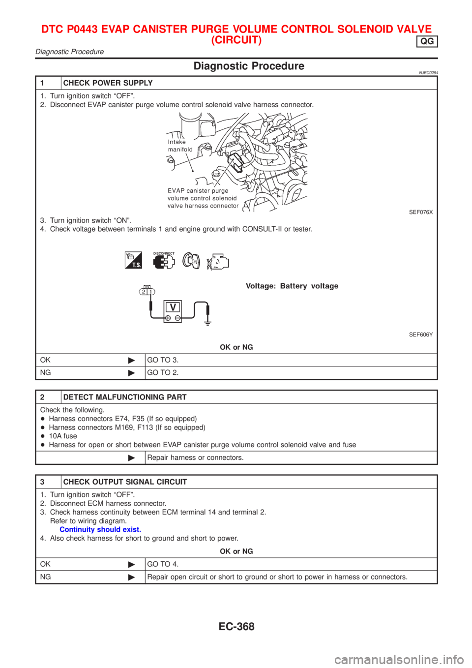
1 CHECK POWER SUPPLY
1. Turn ignition switch ªOFFº.
2. Disconnect EVAP canister purge volume control solenoid valve harness connector.
SEF076X
3. Turn ignition switch ªONº.
4. Check voltage between terminals 1 and engine ground with CONSULT-II or tester.
SEF606Y
OK or NG
OK©GO TO 3.
NG©GO TO 2.
2 DETECT MALFUNCTIONING PART
Check the following.
+Harness connectors E74, F35 (If so equipped)
+Harness connectors M169, F113 (If so equipped)
+10A fuse
+Harness for open or short between EVAP canister purge volume control solenoid valve and fuse
©Repair harness or connectors.
3 CHECK OUTPUT SIGNAL CIRCUIT
1. Turn ignition switch ªOFFº.
2. Disconnect ECM harness connector.
3. Check harness continuity between ECM terminal 14 and terminal 2.
Refer to wiring diagram.
Continuity should exist.
4. Also check harness for short to ground and short to power.
OK or NG
OK©GO TO 4.
NG©Repair open circuit or short to ground or short to power in harness or connectors.
DTC P0443 EVAP CANISTER PURGE VOLUME CONTROL SOLENOID VALVE
(CIRCUIT)
QG
Diagnostic Procedure
EC-368