Page 1012 of 2898
Diagnostic ProcedureNJEC0178
1 RETIGHTEN GROUND SCREWS
1. Turn ignition switch ªOFFº.
2. Loosen and retighten engine ground screws.
JEF104Y
©GO TO 2.
2 CHECK INPUT SIGNAL CIRCUIT
1. Disconnect heated oxygen sensor 2 (rear) harness connector and ECM harness connector.
SEF160Z
2. Check harness continuity between ECM terminal 63 and heated oxygen sensor 2 (rear) harness connector terminal 1.
Refer to wiring diagram.
Continuity should exist.
3. Check harness continuity between ECM terminal 63 [or heated oxygen sensor 2 (rear) harness connector terminal 1]
and ground.
Continuity should not exist.
4. Also check harness for short to ground and short to power.
OK or NG
OK©GO TO 4.
NG©GO TO 3.
3 DETECT MALFUNCTIONING PART
Check the harness for open or short between heated oxygen sensor 2 (rear) and ECM.
©Repair open circuit or short to ground or short to power in harness or connectors.
DTC P0140 HEATED OXYGEN SENSOR 2 (REAR) (HIGH VOLTAGE)QG
Diagnostic Procedure
EC-288
Page 1013 of 2898

4 CHECK GROUND CIRCUIT
1. Check harness continuity between heated oxygen sensor 2 (rear) harness connector terminal 4 and engine ground.
Refer to wiring diagram.
Continuity should exist.
2. Also check harness for short to ground and short to power.
OK or NG
OK©GO TO 5.
NG©Repair open circuit or short to ground or short to power in harness or connectors.
5 CHECK HARNESS CONNECTOR
Check heated oxygen sensor 2 (rear) harness connector for water.
Water should not exist.
OK or NG
OK©GO TO 6.
NG©Repair or replace harness connector.
6 CHECK HEATED OXYGEN SENSOR 2 (REAR)
Refer to ªComponent Inspectionº, EC-289.
OK or NG
OK©GO TO 7.
NG©Replace heated oxygen sensor 2 (rear).
7 CHECK INTERMITTENT INCIDENT
Perform ªTROUBLE DIAGNOSIS FOR INTERMITTENT INCIDENTº, EC-177.
©INSPECTION END
SEF662Y
Component InspectionNJEC0179HEATED OXYGEN SENSOR 2 (REAR)NJEC0179S01With CONSULT-II
1) Start engine and drive vehicle at a speed of more than 70 km/h
(43 MPH) for 2 consecutive minutes.
2) Stop vehicle with engine running.
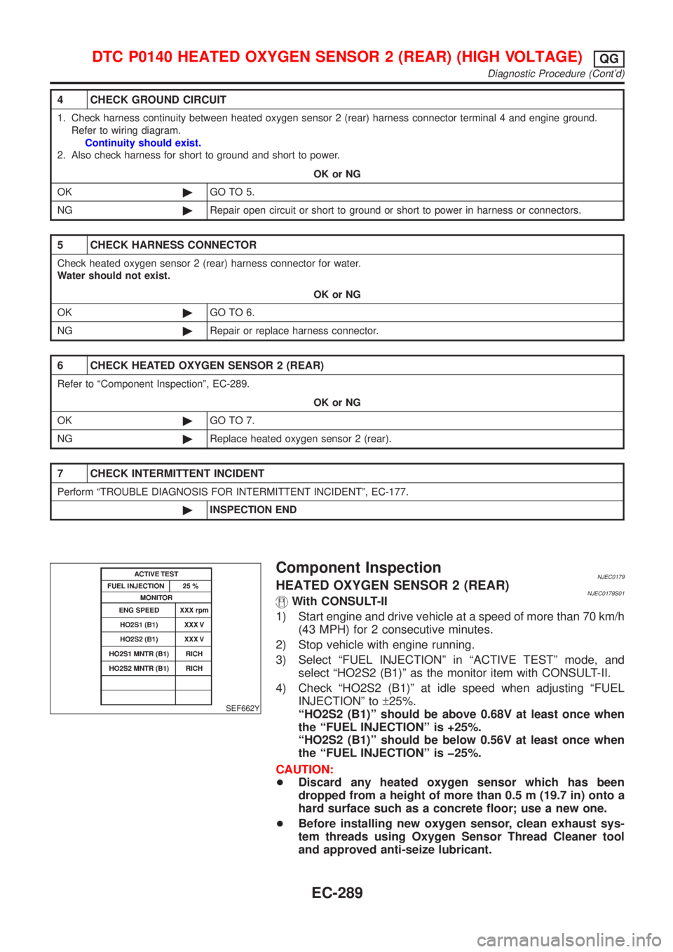
3) Select ªFUEL INJECTIONº in ªACTIVE TESTº mode, and
select ªHO2S2 (B1)º as the monitor item with CONSULT-II.
4) Check ªHO2S2 (B1)º at idle speed when adjusting ªFUEL
INJECTIONº to±25%.
ªHO2S2 (B1)º should be above 0.68V at least once when
the ªFUEL INJECTIONº is +25%.
ªHO2S2 (B1)º should be below 0.56V at least once when
the ªFUEL INJECTIONº is þ25%.
CAUTION:
+Discard any heated oxygen sensor which has been
dropped from a height of more than 0.5 m (19.7 in) onto a
hard surface such as a concrete floor; use a new one.
+Before installing new oxygen sensor, clean exhaust sys-
tem threads using Oxygen Sensor Thread Cleaner tool
and approved anti-seize lubricant.
DTC P0140 HEATED OXYGEN SENSOR 2 (REAR) (HIGH VOLTAGE)QG
Diagnostic Procedure (Cont'd)
EC-289
Page 1017 of 2898
Wiring DiagramNJEC0185SEDAN MODELS AND HATCHBACK MODELS WITH
ECM IN ENGINE COMPARTMENT
NJEC0185S03
HEC788
DTC P0141 HEATED OXYGEN SENSOR 2 HEATER (REAR)QG
Wiring Diagram
EC-293
Page 1018 of 2898
HATCHBACK MODELS WITH ECM IN CABINNJEC0185S04
HEC942
DTC P0141 HEATED OXYGEN SENSOR 2 HEATER (REAR)QG
Wiring Diagram (Cont'd)
EC-294
Page 1019 of 2898
Diagnostic ProcedureNJEC0186
1 CHECK POWER SUPPLY
1. Turn ignition switch ªOFFº.
2. Disconnect heated oxygen sensor 2 (rear) harness connector.
SEF160Z
3. Turn ignition switch ªONº.
4. Check voltage between terminal 2 and ground.
SEF218W
OK or NG
OK©GO TO 3.
NG©GO TO 2.
2 DETECT MALFUNCTIONING PART
Check the following.
+Harness connectors E75, F36
+Harness connectors M21, E106 (Sedan), M160, E175 or M169, F113 (Hatchback)
+Harness for open or short between heated oxygen sensor 2 (rear) and fuse
+10A fuse
©Repair harness or connectors.
3 CHECK GROUND CIRCUIT
1. Turn ignition switch ªOFFº.
2. Disconnect ECM harness connector.
3. Check harness continuity between heated oxygen sensor 2 (rear) harness connector terminal 3 and ECM terminal 3.
Refer to wiring diagram.
Continuity should exist.
4. Also check harness for short to ground and short to power.
OK or NG
OK©GO TO 5.
NG©GO TO 4.
DTC P0141 HEATED OXYGEN SENSOR 2 HEATER (REAR)QG
Diagnostic Procedure
EC-295
Page 1023 of 2898
Wiring DiagramNJEC0190SEDAN MODELS AND HATCHBACK MODELS WITH
ECM IN ENGINE COMPARTMENT
NJEC0190S03
HEC789
DTC P0171 FUEL INJECTION SYSTEM FUNCTION (LEAN SIDE)QG
Wiring Diagram
EC-299
Page 1024 of 2898
HATCHBACK MODELS WITH ECM IN CABINNJEC0190S04
HEC944
DTC P0171 FUEL INJECTION SYSTEM FUNCTION (LEAN SIDE)QG
Wiring Diagram (Cont'd)
EC-300
Page 1025 of 2898

Diagnostic ProcedureNJEC0191
1 CHECK EXHAUST AIR LEAK
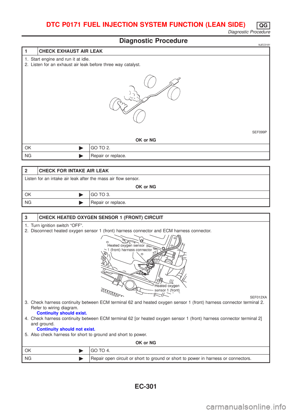
1. Start engine and run it at idle.
2. Listen for an exhaust air leak before three way catalyst.
SEF099P
OK or NG
OK©GO TO 2.
NG©Repair or replace.
2 CHECK FOR INTAKE AIR LEAK
Listen for an intake air leak after the mass air flow sensor.
OK or NG
OK©GO TO 3.
NG©Repair or replace.
3 CHECK HEATED OXYGEN SENSOR 1 (FRONT) CIRCUIT
1. Turn ignition switch ªOFFº.
2. Disconnect heated oxygen sensor 1 (front) harness connector and ECM harness connector.
SEF012XA
3. Check harness continuity between ECM terminal 62 and heated oxygen sensor 1 (front) harness connector terminal 2.
Refer to wiring diagram.
Continuity should exist.
4. Check harness continuity between ECM terminal 62 [or heated oxygen sensor 1 (front) harness connector terminal 2]
and ground.
Continuity should not exist.
5. Also check harness for short to ground and short to power.
OK or NG
OK©GO TO 4.
NG©Repair open circuit or short to ground or short to power in harness or connectors.
DTC P0171 FUEL INJECTION SYSTEM FUNCTION (LEAN SIDE)QG
Diagnostic Procedure
EC-301