Page 1031 of 2898
Wiring DiagramNJEC0194SEDAN MODELS AND HATCHBACK MODELS WITH
ECM IN ENGINE COMPARTMENT
NJEC0194S03
HEC789
DTC P0172 FUEL INJECTION SYSTEM FUNCTION (RICH SIDE)QG
Wiring Diagram
EC-307
Page 1032 of 2898
HATCHBACK MODELS WITH ECM IN CABINNJEC0194S04
HEC944
DTC P0172 FUEL INJECTION SYSTEM FUNCTION (RICH SIDE)QG
Wiring Diagram (Cont'd)
EC-308
Page 1033 of 2898
Diagnostic ProcedureNJEC0195
1 CHECK FOR EXHAUST AIR LEAK
1. Start engine and run it at idle.
2. Listen for an exhaust air leak before the three way catalyst.
SEF099P
OK or NG
OK©GO TO 2.
NG©Repair or replace.
2 CHECK HEATED OXYGEN SENSOR 1 (FRONT) CIRCUIT
1. Turn ignition switch ªOFFº.
2. Disconnect heated oxygen sensor 1 (front) harness connector and ECM harness connector.
SEF012XA
3. Check harness continuity between ECM terminal 62 and heated oxygen sensor 1 (front) harness connector terminal 2.
Refer to wiring diagram.
Continuity should exist.
4. Check harness continuity between ECM terminal 62 [or heated oxygen sensor 1 (front) harness connector terminal 2]
and ground.
Continuity should not exist.
5. Also check harness for short to ground and short to power.
OK or NG
OK©GO TO 3.
NG©Repair open circuit or short to ground or short to power in harness or connectors.
DTC P0172 FUEL INJECTION SYSTEM FUNCTION (RICH SIDE)QG
Diagnostic Procedure
EC-309
Page 1039 of 2898
Wiring DiagramNJEC0199
HEC897
DTC P0180 FUEL TANK TEMPERATURE SENSOR (WHERE FITTED)QG
Wiring Diagram
EC-315
Page 1040 of 2898

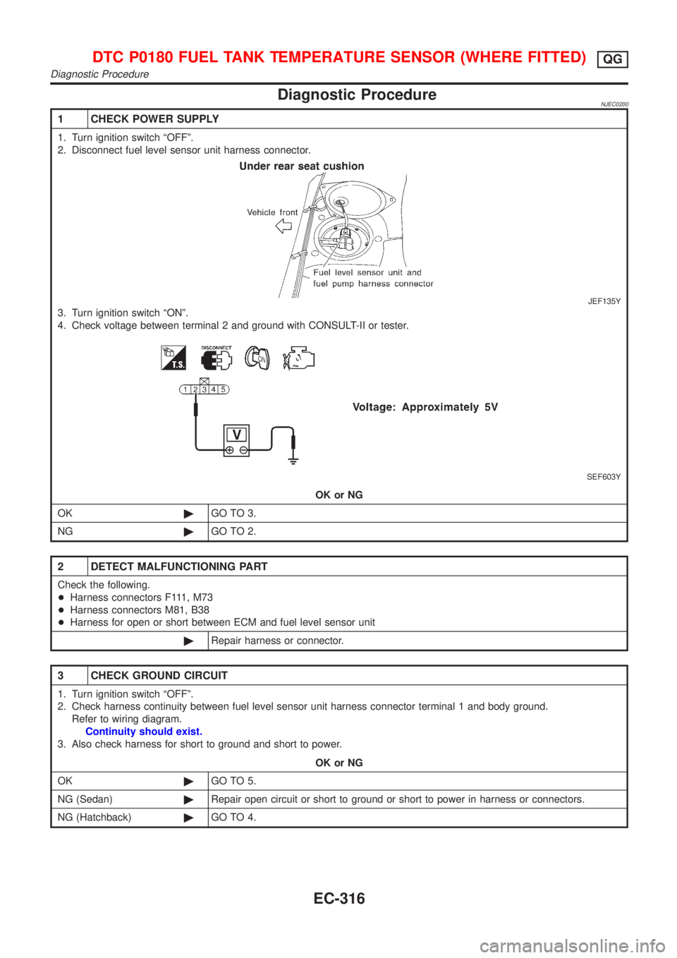
Diagnostic ProcedureNJEC0200
1 CHECK POWER SUPPLY
1. Turn ignition switch ªOFFº.
2. Disconnect fuel level sensor unit harness connector.
JEF135Y
3. Turn ignition switch ªONº.
4. Check voltage between terminal 2 and ground with CONSULT-II or tester.
SEF603Y
OK or NG
OK©GO TO 3.
NG©GO TO 2.
2 DETECT MALFUNCTIONING PART
Check the following.
+Harness connectors F111, M73
+Harness connectors M81, B38
+Harness for open or short between ECM and fuel level sensor unit
©Repair harness or connector.
3 CHECK GROUND CIRCUIT
1. Turn ignition switch ªOFFº.
2. Check harness continuity between fuel level sensor unit harness connector terminal 1 and body ground.
Refer to wiring diagram.
Continuity should exist.
3. Also check harness for short to ground and short to power.
OK or NG
OK©GO TO 5.
NG (Sedan)©Repair open circuit or short to ground or short to power in harness or connectors.
NG (Hatchback)©GO TO 4.
DTC P0180 FUEL TANK TEMPERATURE SENSOR (WHERE FITTED)QG
Diagnostic Procedure
EC-316
Page 1049 of 2898
Wiring DiagramNJEC0210
HEC791
DTC P0325 KNOCK SENSOR (KS)QG
Wiring Diagram
EC-325
Page 1050 of 2898
Diagnostic ProcedureNJEC0211
1 RETIGHTEN GROUND SCREWS
Loosen and retighten engine ground screws.
JEF104Y
©GO TO 2.
2 CHECK INPUT SIGNAL CIRCUIT-1
1. Turn ignition switch ªOFFº.
2. Disconnect ECM harness connector and knock sensor harness connector.
JEF110Y
3. Check harness continuity between knock sensor signal terminal 1 and ECM terminal 81.
Refer to wiring diagram.
Continuity should exist.
4. Also check harness for short to ground and short to power.
OK or NG
OK©GO TO 4.
NG©GO TO 3.
3 DETECT MALFUNCTIONING PART
Check the harness for open or short between knock sensor and ECM.
©Repair open circuit or short to ground or short to power in harness or connectors.
4 CHECK KNOCK SENSOR
Refer to ªComponent Inspectionº, EC-327.
OK or NG
OK©GO TO 5.
NG©Replace knock sensor.
DTC P0325 KNOCK SENSOR (KS)QG
Diagnostic Procedure
EC-326
Page 1054 of 2898
Wiring DiagramNJEC0555SEDAN MODELS AND HATCHBACK MODELS WITH
ECM IN ENGINE COMPARTMENT
NJEC0555S01
HEC792
DTC P0335 CRANKSHAFT POSITION SENSOR (POS)QG
Wiring Diagram
EC-330