Page 594 of 2898
Wheel Sensor or RotorNJBR0098DIAGNOSTIC PROCEDURENJBR0098S01(Malfunction code No. 21, 22, 25, 26, 31, 32, 35, 36 or 18 for
models with self-diagnosis function)
NOTE:
Wheel position should be identified by code No. except code No.
18 (sensor rotor).
1 INSPECTION START
Wheel sensor inspection
SBR476EB
©GO TO 2.
2 CHECK CONNECTOR
1. Disconnect connectors from control unit and wheel sensor of malfunction code No. Check terminals for damage or
loose connections. Then reconnect connectors.
2. Carry out self-diagnosis again.
Does warning lamp activate again?
Ye s©GO TO 3.
No©INSPECTION END
TROUBLE DIAGNOSES FOR SELF-DIAGNOSTIC ITEMSABS
Wheel Sensor or Rotor
BR-78
Page 595 of 2898
3 CHECK WHEEL SENSOR CIRCUIT
1. Disconnect control unit connector.
2. Check resistance between control unit connector terminals.
Code No. 21 or 22 (Front RH wheel)
Terminals 4 and 5
Code No. 25 or 26 (Front LH wheel)
Terminals 6 and 7
Code No. 31 or 32 (Rear RH wheel)
Terminals 1 and 3
Code No. 35 or 36 (Rear LH wheel)
Terminals 8 and 9
Resistance: 1.44 - 1.76 kW
SBR477EC
Is resistance 1.44 - 1.76 kW?
Ye s©GO TO 5.
No©GO TO 4.
4 CHECK WHEEL SENSOR
Check resistance of each sensor. (See NOTE.)
Resistance: 1.44 - 1.76 kW
SBR478EC
Is resistance 1.44 - 1.76 kW?
Ye s©Repair harness and connectors between control unit connector and wheel sensor con-
nector.
No©Replace wheel sensor.
5 CHECK TIRE
Check for inflation pressure, wear and size of each tire.
Are tire pressure and size correct and is tire wear within specifications?
Ye s©GO TO 6.
No©Adjust tire pressure or replace tire(s).
TROUBLE DIAGNOSES FOR SELF-DIAGNOSTIC ITEMSABS
Wheel Sensor or Rotor (Cont'd)
BR-79
Page 596 of 2898
6 CHECK WHEEL BEARING
Check wheel bearing axial end play.
Check clearance between sensor and rotor.
Clearance:
Front
0.7 - 1.8 mm (0.028 - 0.071 in)
Rear
0.4 - 1.5 mm (0.016 - 0.059 in)
SBR333E
SBR069CA
Is axial end play and clearance within specifications?
Ye s©GO TO 7.
No©Clean sensor fixing portion, or replace sensor.
7 CHECK SENSOR ROTOR
Check sensor rotor for teeth damage.
Is sensor rotor free from damage?
Ye s©Check control unit pin terminals for damage or the connection of control unit harness
connector. Reconnect control unit harness connector. Then retest.
No©Replace sensor rotor.
TROUBLE DIAGNOSES FOR SELF-DIAGNOSTIC ITEMSABS
Wheel Sensor or Rotor (Cont'd)
BR-80
Page 605 of 2898

1. ABS Works FrequentlyNJBR0104
1 CHECK BRAKE FLUID PRESSURE
Check brake fluid pressure distribution.
Is brake fluid pressure distribution normal?
Ye s©GO TO 2.
No©Perform Preliminary Check. Refer to BR-72.
2 CHECK WHEEL SENSOR
1. Check wheel sensor connector for terminal damage or loose connections.
2. Perform wheel sensor mechanical check.
Refer to ªWheel Sensor or Rotorº, BR-78.
Are wheel sensors functioning properly?
Ye s©GO TO 3.
No©Repair.
3 CHECK FRONT AXLE
Check front and rear axles for excessive looseness. Refer to AX section, ªFront Wheel Bearingº, ªON-VEHICLE SERVICEº
and ªRear Wheel Bearingº, ªON-VEHICLE SERVICEº.
Is front axle installed properly?
Ye s©Go to ª3. CHECK WARNING LAMP INDICATIONº in ª2. Unexpected Pedal Actionº,
BR-89.
No©Repair.
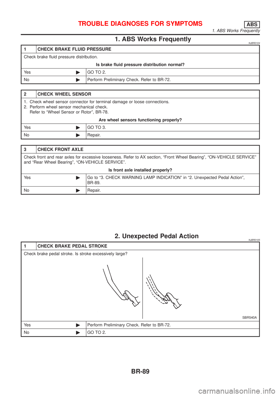
2. Unexpected Pedal ActionNJBR0105
1 CHECK BRAKE PEDAL STROKE
Check brake pedal stroke. Is stroke excessively large?
SBR540A
Ye s©Perform Preliminary Check. Refer to BR-72.
No©GO TO 2.
TROUBLE DIAGNOSES FOR SYMPTOMSABS
1. ABS Works Frequently
BR-89
Page 606 of 2898

2 CHECK CONNECTOR AND PERFORMANCE
1. Disconnect ABS actuator and electric unit connector.
2. Check whether brake is effective.
OK or NG
Ye s©GO TO 3.
No©Perform Preliminary Check. Refer to BR-72.
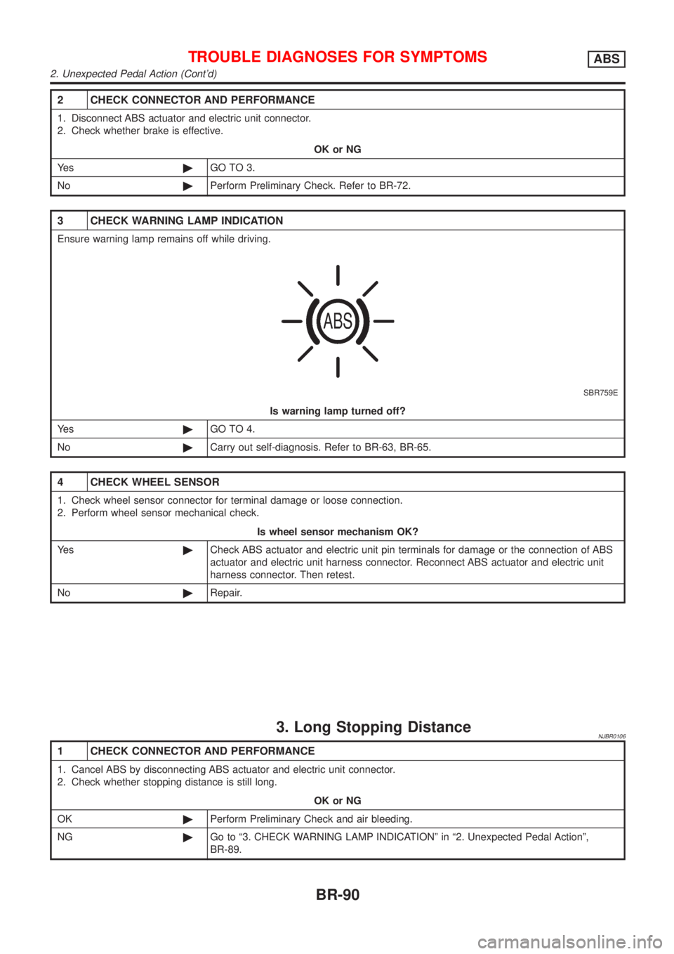
3 CHECK WARNING LAMP INDICATION
Ensure warning lamp remains off while driving.
SBR759E
Is warning lamp turned off?
Ye s©GO TO 4.
No©Carry out self-diagnosis. Refer to BR-63, BR-65.
4 CHECK WHEEL SENSOR
1. Check wheel sensor connector for terminal damage or loose connection.
2. Perform wheel sensor mechanical check.
Is wheel sensor mechanism OK?
Ye s©Check ABS actuator and electric unit pin terminals for damage or the connection of ABS
actuator and electric unit harness connector. Reconnect ABS actuator and electric unit
harness connector. Then retest.
No©Repair.
3. Long Stopping DistanceNJBR0106
1 CHECK CONNECTOR AND PERFORMANCE
1. Cancel ABS by disconnecting ABS actuator and electric unit connector.
2. Check whether stopping distance is still long.
OK or NG
OK©Perform Preliminary Check and air bleeding.
NG©Go to ª3. CHECK WARNING LAMP INDICATIONº in ª2. Unexpected Pedal Actionº,
BR-89.
TROUBLE DIAGNOSES FOR SYMPTOMSABS
2. Unexpected Pedal Action (Cont'd)
BR-90
Page 608 of 2898

5. Pedal Vibration and Noise=NJBR0108
1 INSPECTION START
Pedal vibration and noise inspection
SAT797A
©GO TO 2.
2 CHECK SYMPTOM
1. Apply brake.
2. Start engine.
Does the symptom appear only when engine is started?
Ye s©Carry out self-diagnosis. Refer to BR-63, BR-65.
No©GO TO 3.
3 RECHECK SYMPTOM
Does the symptom appear when electrical equipment switches (such as headlamp) are operated?
Ye s©GO TO 4.
No©Go to ª3. CHECK WARNING LAMP INDICATIONº in ª2. Unexpected Pedal Actionº,
BR-89.
4 CHECK WHEEL SENSOR
Check wheel sensor shield ground. For location of shield ground, refer to wiring diagram and ªHARNESS LAYOUTº in EL
section.
Is wheel sensor shield grounded properly?
Ye s©Check ABS actuator and electric unit pin terminals for damage or the connection of ABS
actuator and electric unit harness connector. Reconnect ABS actuator and electric unit
harness connector. Then retest.
No©Repair.
NOTE:
ABS may operate and cause vibration under any of the following
conditions.
+Applying brake gradually when shifting or operating clutch.
+Low friction (slippery) road.
+High speed cornering.
+Driving over bumps and pot holes.
+Engine speed is over 5,000 rpm with vehicle stopped.
TROUBLE DIAGNOSES FOR SYMPTOMSABS
5. Pedal Vibration and Noise
BR-92
Page 613 of 2898
NJBR0111
CAUTION:
Be careful not to damage sensor edge and sensor rotor teeth.
When removing the front or rear wheel hub assembly, first
remove the ABS wheel sensor from the assembly. Failure to
do so may result in damage to the sensor wires making the
sensor inoperative.
Wheel SensorsNJBR0111S01
SBR902D
REMOVAL AND INSTALLATIONABS
BR-97
Page 615 of 2898
SBR984C
SBR873CA
Sensor RotorNJBR0111S02REMOVALNJBR0111S02011. Remove the drive shaft and rear wheel hub. Refer to ªDrive
Shaftº and ªWheel Hubº in AX section.
2. Remove the sensor rotor using suitable puller, drift and bear-
ing replacer.
SBR985C
INSTALLATIONNJBR0111S0202Install the sensor rotor. For front sensor rotor, use hammer and
wooden block. For rear sensor rotor, use suitable drift and press.
+Always replace sensor rotor with new one.
SBR986C
+Pay attention to the dimension of rear sensor rotor as show in
figure.
h: 17.7 - 18.7 mm (0.697 - 0.736 in)
REMOVAL AND INSTALLATIONABS
Sensor Rotor
BR-99