Page 2001 of 2898

DIAGNOSTIC PROCEDURE 5=NJEL0411S09Self-diagnostic results:
ªID DISCORD, IMM-ECMº displayed on CONSULT-II screen
1 CONFIRM SELF-DIAGNOSTIC RESULTS
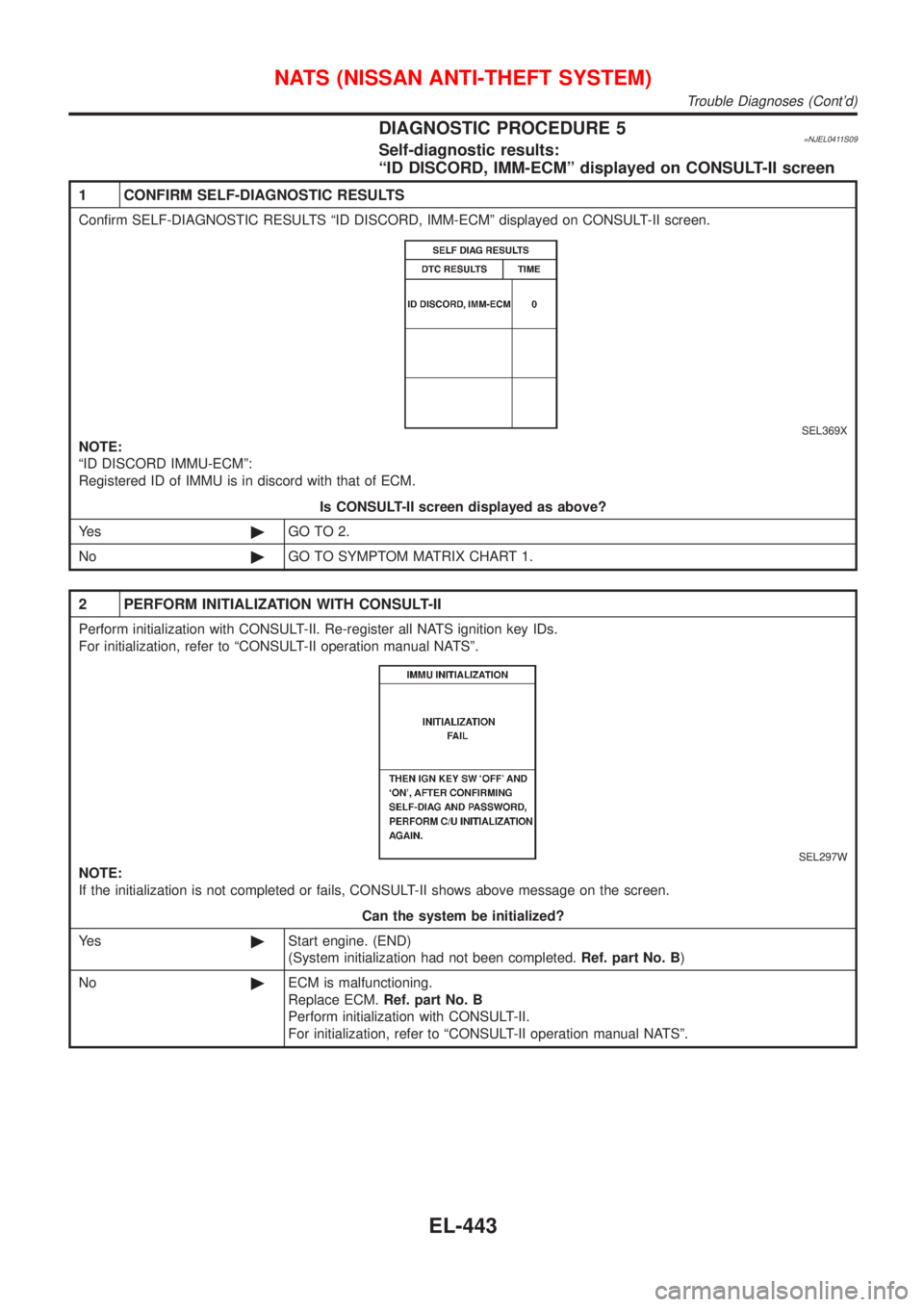
Confirm SELF-DIAGNOSTIC RESULTS ªID DISCORD, IMM-ECMº displayed on CONSULT-II screen.
SEL369X
NOTE:
ªID DISCORD IMMU-ECMº:
Registered ID of IMMU is in discord with that of ECM.
Is CONSULT-II screen displayed as above?
Ye s©GO TO 2.
No©GO TO SYMPTOM MATRIX CHART 1.
2 PERFORM INITIALIZATION WITH CONSULT-II
Perform initialization with CONSULT-II. Re-register all NATS ignition key IDs.
For initialization, refer to ªCONSULT-II operation manual NATSº.
SEL297W
NOTE:
If the initialization is not completed or fails, CONSULT-II shows above message on the screen.
Can the system be initialized?
Ye s©Start engine. (END)
(System initialization had not been completed.Ref. part No. B)
No©ECM is malfunctioning.
Replace ECM.Ref. part No. B
Perform initialization with CONSULT-II.
For initialization, refer to ªCONSULT-II operation manual NATSº.
NATS (NISSAN ANTI-THEFT SYSTEM)
Trouble Diagnoses (Cont'd)
EL-443
Page 2004 of 2898
DIAGNOSTIC PROCEDURE 7=NJEL0411S11Self-diagnostic results:
ªLOCK MODEº displayed on CONSULT-II screen
1 CONFIRM SELF-DIAGNOSTIC RESULTS
Confirm SELF-DIAGNOSTIC RESULTS ªLOCK MODEº is displayed on CONSULT-II screen.
SEL371X
Is CONSULT-II screen displayed as above?
Ye s©GO TO 2.
No©GO TO SYMPTOM MATRIX CHART 1.
2 ESCAPE FROM LOCK MODE
1. Turn ignition switch OFF.
2. Turn ignition switch ON with registered key. (Do not start engine.) Wait 5 seconds.
3. Return the key to OFF position.
4. Repeat steps 2 and 3 twice (total of three cycles).
5. Start the engine.
Does engine start?
Ye s©System is OK.
(Now system is escaped from ªLOCK MODEº.)
No©GO TO 3.
3 CHECK IMMU ILLUSTRATION
Check IMMU installation. Refer to ªHow to Replace IMMUº in EL-449.
OK or NG
OK©GO TO 4.
NG©Reinstall IMMU correctly.
NATS (NISSAN ANTI-THEFT SYSTEM)
Trouble Diagnoses (Cont'd)
EL-446
Page 2010 of 2898

SEL504X
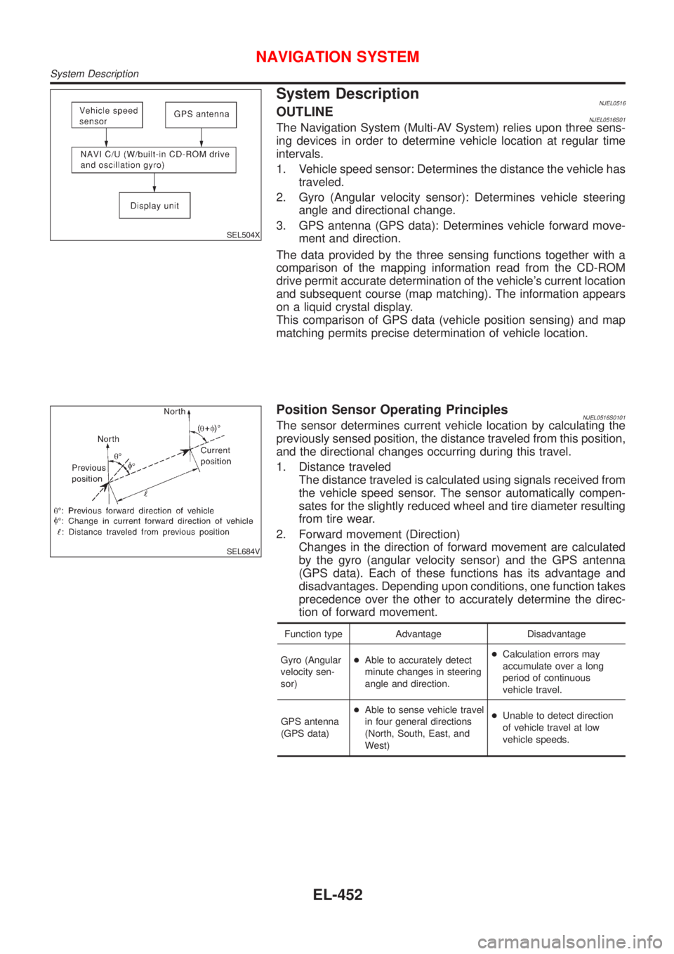
System DescriptionNJEL0516OUTLINENJEL0516S01The Navigation System (Multi-AV System) relies upon three sens-
ing devices in order to determine vehicle location at regular time
intervals.
1. Vehicle speed sensor: Determines the distance the vehicle has
traveled.
2. Gyro (Angular velocity sensor): Determines vehicle steering
angle and directional change.
3. GPS antenna (GPS data): Determines vehicle forward move-
ment and direction.
The data provided by the three sensing functions together with a
comparison of the mapping information read from the CD-ROM
drive permit accurate determination of the vehicle's current location
and subsequent course (map matching). The information appears
on a liquid crystal display.
This comparison of GPS data (vehicle position sensing) and map
matching permits precise determination of vehicle location.
SEL684V
Position Sensor Operating PrinciplesNJEL0516S0101The sensor determines current vehicle location by calculating the
previously sensed position, the distance traveled from this position,
and the directional changes occurring during this travel.
1. Distance traveled
The distance traveled is calculated using signals received from
the vehicle speed sensor. The sensor automatically compen-
sates for the slightly reduced wheel and tire diameter resulting
from tire wear.
2. Forward movement (Direction)
Changes in the direction of forward movement are calculated
by the gyro (angular velocity sensor) and the GPS antenna
(GPS data). Each of these functions has its advantage and
disadvantages. Depending upon conditions, one function takes
precedence over the other to accurately determine the direc-
tion of forward movement.
Function type Advantage Disadvantage
Gyro (Angular
velocity sen-
sor)+Able to accurately detect
minute changes in steering
angle and direction.+Calculation errors may
accumulate over a long
period of continuous
vehicle travel.
GPS antenna
(GPS data)+Able to sense vehicle travel
in four general directions
(North, South, East, and
West)+Unable to detect direction
of vehicle travel at low
vehicle speeds.
NAVIGATION SYSTEM
System Description
EL-452
Page 2012 of 2898

for example, when the vehicle is in a tunnel, in a parking lot
inside building, under an elevated superhighway or near strong
power lines, the location may not be detected. Turbulent/
electric weather conditions may also affect positioning perfor-
mance. If something is placed on the antenna, the radio wave
from GPS satellites may not be received.
SEL507X
COMPONENT DESCRIPTIONNJEL0516S02NAVI Control UnitNJEL0516S0201+The gyro (angular speed sensor) and the CD-ROM drive are
built-in units that control the navigation functions.
+Signals are received from the gyro, the vehicle speed sensor,
and the GPS antenna. Vehicle location is determined by com-
bining this data with the data contained in the CD-ROM map.
Locational information is shown on liquid crystal display panel.
SEL506X
CD-ROM DriverNJEL0516S0202Maps, traffic control regulations, and other pertinent information
can be easily red from the CD-ROM disc.
Map CD-ROMNJEL0516S0203+The map CD-ROM has maps, traffic control regulations, and
other pertinent information.
+To improve CD-ROM map matching and route determination
functions, the CD-ROM uses an exclusive Nissan format.
Therefore, the use of a CD-ROM provided by other manufac-
turers cannot be used.
SEL690V
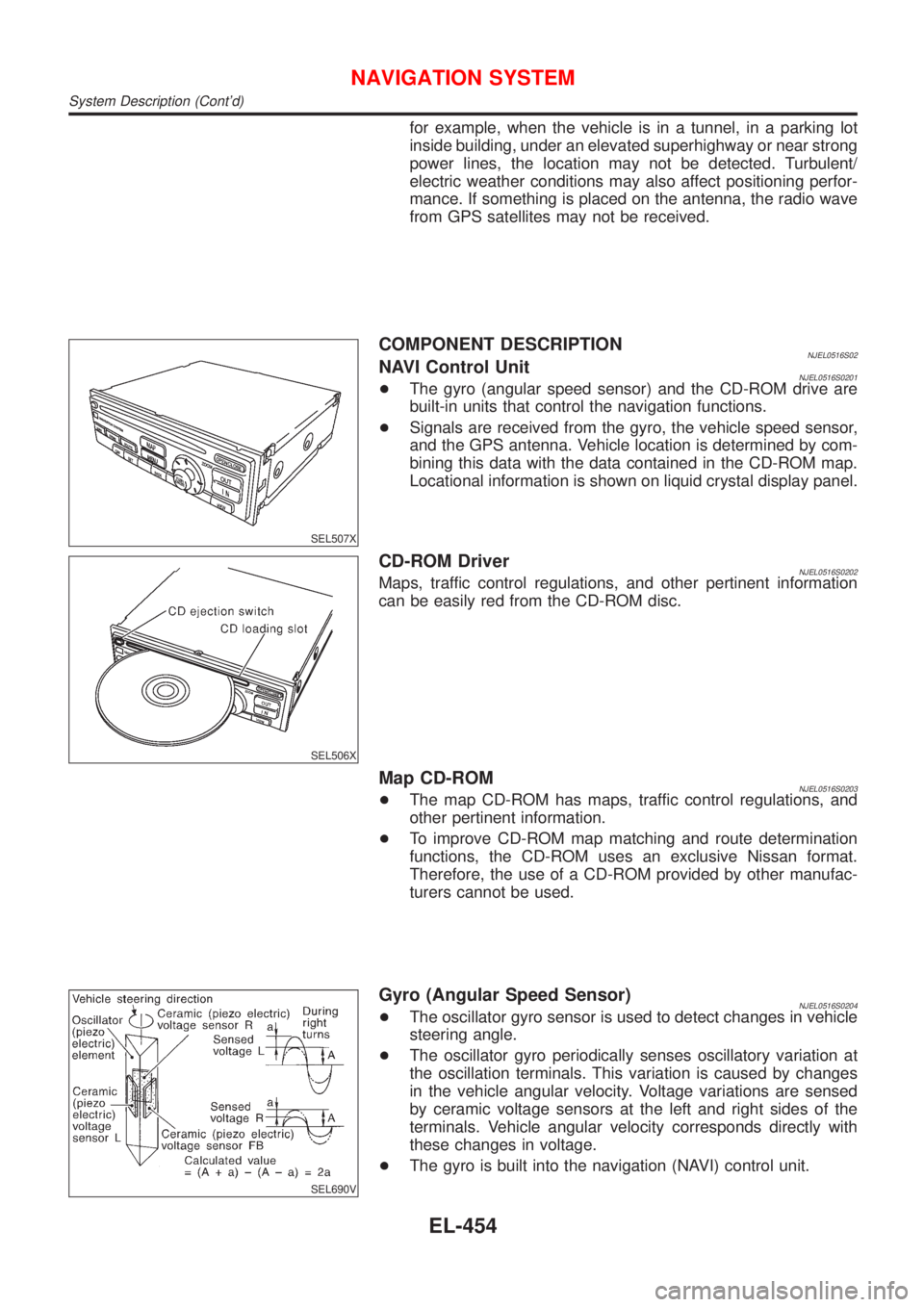
Gyro (Angular Speed Sensor)NJEL0516S0204+The oscillator gyro sensor is used to detect changes in vehicle
steering angle.
+The oscillator gyro periodically senses oscillatory variation at
the oscillation terminals. This variation is caused by changes
in the vehicle angular velocity. Voltage variations are sensed
by ceramic voltage sensors at the left and right sides of the
terminals. Vehicle angular velocity corresponds directly with
these changes in voltage.
+The gyro is built into the navigation (NAVI) control unit.
NAVIGATION SYSTEM
System Description (Cont'd)
EL-454
Page 2013 of 2898
MAP DISPLAY
BIRDVIEW
R
SEL524X
BIRDVIEWTNJEL0516S0205The BIRDVIEWTprovides a detailed and easily seen display of
road conditions covering the vehicle's immediate to distant area.
SEL691V
DescriptionNJEL0516S0206+Display area: Trapezoidal representation showing approximate
distances (Wn, D, and Wd).
+Ten horizontal grid lines indicate display width while six verti-
cal grid lines indicate display depth and direction.
+Drawing line area shows open space, depth, and immediate
front area. Each area is to a scale of approximately 5:6:25.
+Pushing the ªZOOM INº button during operation displays the
scale change and the view point height on the left side of the
screen.
The height of the view point increases or decreases when
ªZOOMº or ªWIDEº is selected with the joystick.
NAVIGATION SYSTEM
System Description (Cont'd)
EL-455
Page 2014 of 2898
MAP DISPLAY=NJEL0516S03
SEL525X
Function of each icon is as follows:
1) Azimuth indication
2) Position marker
The tip of the arrow shows the current position. The shaft of
the arrow indicates the direction in which the vehicle is travel-
ing.
3) GPS reception signal (indicates current reception conditions)
4) Distance display (shows the distance in a reduced scale)
NAVIGATION SYSTEM
System Description (Cont'd)
EL-456
Page 2015 of 2898
FUNCTION OF PANEL SWITCH=NJEL0516S04Display with Pushed ªDESTº SwitchNJEL0516S0401
SEL615X
The function of each icon is as follows:
Icon Description
Address Book Favorite areas can be saved to memory.
Address (City/Street) The information can be searched from the address.
Point of Interest (POI) The information of favorite areas can be searched.
Previous Dest.The previous ten destinations stored in memory are
displayed.
City Centre The information can be searched from city name.
Map The information can be searched from the map.
CountryWhen two or more countries are included in a map
CD-ROM, the destination can be searched for under
the country name.
NAVIGATION SYSTEM
System Description (Cont'd)
EL-457
Page 2016 of 2898

Display with Pushed ªROUTEº Switch=NJEL0516S0402
SEL526X
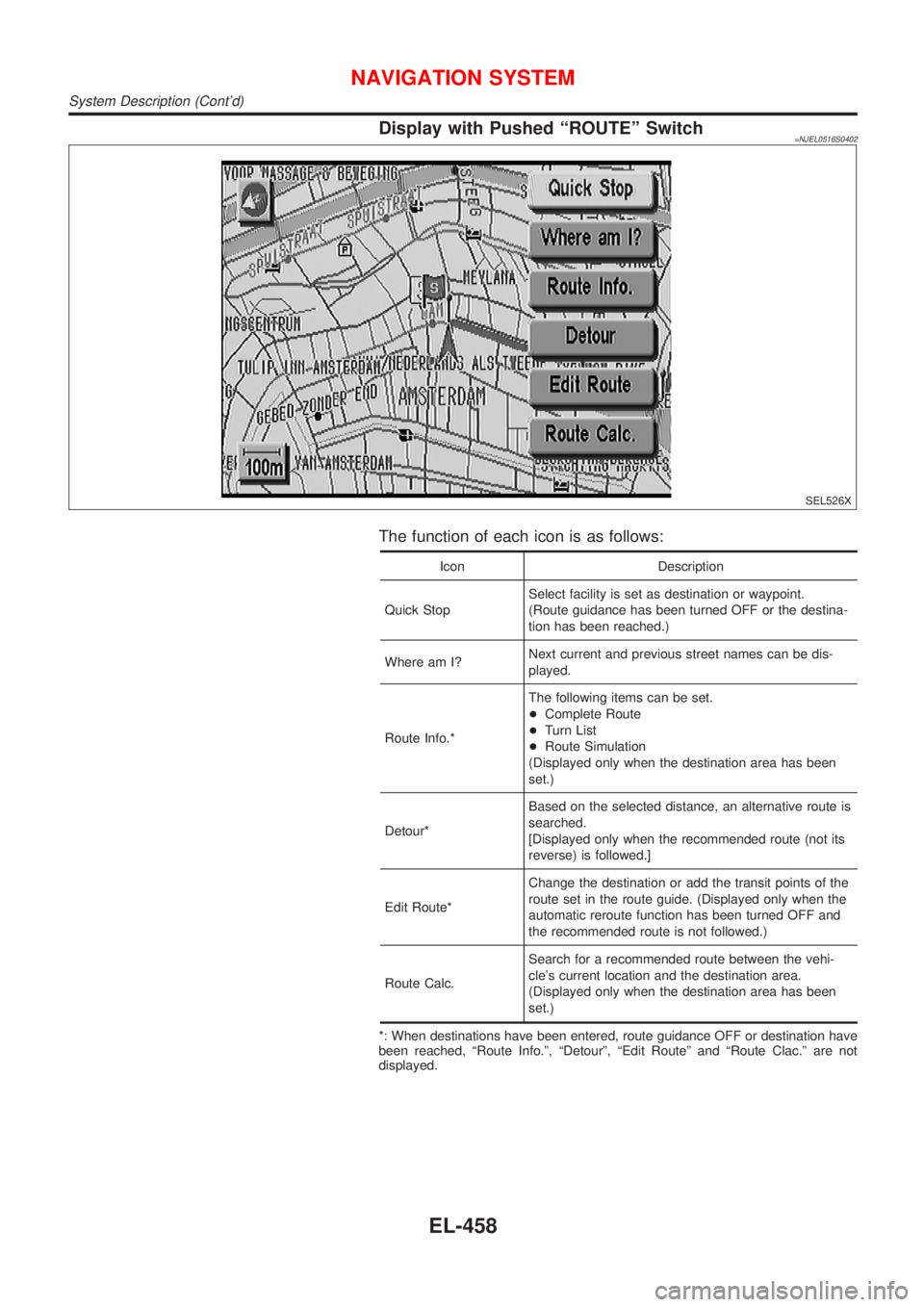
The function of each icon is as follows:
Icon Description
Quick StopSelect facility is set as destination or waypoint.
(Route guidance has been turned OFF or the destina-
tion has been reached.)
Where am I?Next current and previous street names can be dis-
played.
Route Info.*The following items can be set.
+Complete Route
+Turn List
+Route Simulation
(Displayed only when the destination area has been
set.)
Detour*Based on the selected distance, an alternative route is
searched.
[Displayed only when the recommended route (not its
reverse) is followed.]
Edit Route*Change the destination or add the transit points of the
route set in the route guide. (Displayed only when the
automatic reroute function has been turned OFF and
the recommended route is not followed.)
Route Calc.Search for a recommended route between the vehi-
cle's current location and the destination area.
(Displayed only when the destination area has been
set.)
*: When destinations have been entered, route guidance OFF or destination have
been reached, ªRoute Info.º, ªDetourº, ªEdit Routeº and ªRoute Clac.º are not
displayed.
NAVIGATION SYSTEM
System Description (Cont'd)
EL-458