Page 1360 of 2898
the ªDTC Confirmation Procedureº, the moment a malfunction
is found the DTC will be displayed. Refer to GI-22, ªIncident
Simulation Testsº.
2) ªMANU TRIGº
+If the malfunction is displayed as soon as ªDATA MONITORº
is selected, reset CONSULT-II to ªMANU TRIGº. By selecting
ªMANU TRIGº you can monitor and store the data. The data
can be utilized for further diagnosis, such as a comparison with
the value for the normal operating condition.
SEF720X
ON BOARD DIAGNOSTIC SYSTEM DESCRIPTIONYD
CONSULT-II (Cont'd)
EC-636
Page 1364 of 2898

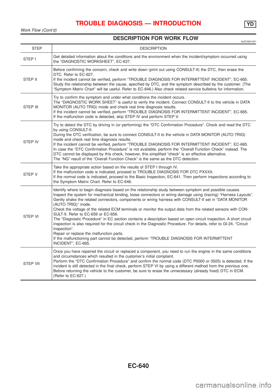
DESCRIPTION FOR WORK FLOWNJEC0631S01
STEP DESCRIPTION
STEP IGet detailed information about the conditions and the environment when the incident/symptom occurred using
the ªDIAGNOSTIC WORKSHEETº, EC-637.
STEP IIBefore confirming the concern, check and write down (print out using CONSULT-II) the DTC, then erase the
DTC. Refer to EC-627.
If the incident cannot be verified, perform ªTROUBLE DIAGNOSIS FOR INTERMITTENT INCIDENTº, EC-665.
Study the relationship between the cause, specified by DTC, and the symptom described by the customer. (The
ªSymptom Matrix Chartº will be useful. Refer to EC-646.) Also check related service bulletins for information.
STEP IIITry to confirm the symptom and under what conditions the incident occurs.
The ªDIAGNOSTIC WORK SHEETº is useful to verify the incident. Connect CONSULT-II to the vehicle in DATA
MONITOR (AUTO TRIG) mode and check real time diagnosis results.
If the incident cannot be verified, perform ªTROUBLE DIAGNOSIS FOR INTERMITTENT INCIDENTº, EC-665.
If the malfunction code is detected, skip STEP IV and perform STEP V.
STEP IVTry to detect the DTC by driving in (or performing) the ªDTC Confirmation Procedureº. Check and read the DTC
by using CONSULT-II.
During the DTC verification, be sure to connect CONSULT-II to the vehicle in DATA MONITOR (AUTO TRIG)
mode and check real time diagnosis results.
If the incident cannot be verified, perform ªTROUBLE DIAGNOSIS FOR INTERMITTENT INCIDENTº, EC-665.
In case the ªDTC Confirmation Procedureº is not available, perform the ªOverall Function Checkº instead. The
DTC cannot be displayed by this check, however, this simplified ªcheckº is an effective alternative.
The ªNGº result of the ªOverall Function Checkº is the same as the DTC detection.
STEP VTake the appropriate action based on the results of STEP I through IV.
If the malfunction code is indicated, proceed to TROUBLE DIAGNOSIS FOR DTC PXXXX.
If the normal code is indicated, proceed to the Basic Inspection, EC-641. Then perform inspections according to
the Symptom Matrix Chart. Refer to EC-646.
STEP VIIdentify where to begin diagnosis based on the relationship study between symptom and possible causes.
Inspect the system for mechanical binding, loose connectors or wiring damage using (tracing) ªHarness Layoutsº.
Gently shake the related connectors, components or wiring harness with CONSULT-II set in ªDATA MONITOR
(AUTO TRIG)º mode.
Check the voltage of the related ECM terminals or monitor the output data from the related sensors with CON-
SULT-II. Refer to EC-659 or EC-656.
The ªDiagnostic Procedureº in EC section contains a description based on open circuit inspection. A short circuit
inspection is also required for the circuit check in the Diagnostic Procedure. For details, refer to GI-24, ªCircuit
Inspectionº.
Repair or replace the malfunction parts.
If the malfunctioning part cannot be detected, perform ªTROUBLE DIAGNOSIS FOR INTERMITTENT
INCIDENTº, EC-665.
STEP VIIOnce you have repaired the circuit or replaced a component, you need to run the engine in the same conditions
and circumstances which resulted in the customer's initial complaint.
Perform the ªDTC Confirmation Procedureº and confirm the normal code (DTC P0000 or 0505) is detected. If the
incident is still detected in the final check, perform STEP VI by using a different method from the previous one.
Before returning the vehicle to the customer, be sure to erase the unnecessary (already fixed) DTC in ECM.
(Refer to EC-627.)
TROUBLE DIAGNOSIS Ð INTRODUCTIONYD
Work Flow (Cont'd)
EC-640
Page 1381 of 2898
MONITOR ITEM CONDITION SPECIFICATION
BARO SEN+Ignition switch: ONAltitude
Approx.0m(0ft): Approx. 100.62
kPa (1.0062 bar, 1.026 kg/cm
2,
14.59 psi)
Approx. 1,000 m (3,281 ft): Approx.
88.95 kPa (0.8895 bar, 0.907
kg/cm
2, 12.90 psi)
Approx. 1,500 m (4,922 ft): Approx.
83.16 kPa (0.8316 bar, 0.848
kg/cm
2, 12.06 psi)
Approx. 2,000 m (6,562 ft): Approx.
78.36 kPa (0.7836 bar, 0.799
kg/cm
2, 11.36 psi)
EGR VOL CON/V+Engine: After warming up
+Air conditioner switch: ªOFFº
+Shift lever: Neutral position
+No-loadAfter one minute at idle More than 10 steps
Revving engine from idle to 3,200
rpm0 steps
*1: On models not equipped with park/neutral position (PNP) switch, ªOFFº is always displayed regardless of gear shift position.
TROUBLE DIAGNOSIS Ð GENERAL DESCRIPTIONYD
CONSULT-II Reference Value in Data Monitor Mode (Cont'd)
EC-657
Page 1439 of 2898
Diagnostic ProcedureNJEC0737
1 INSPECTION START
With CONSULT-II
1. Turn ignition switch ªONº.
2. Select ªSELF DIAG RESULTSº mode with CONSULT-II.
3. Touch ªERASEº.
4. Perform ªDTC Confirmation Procedureº, EC-714, again.
5. Is the DTC P1107 displayed again?
Without CONSULT-II
1. Turn ignition switch ªONº.
2. Erase the Diagnostic Test Mode II (Self-diagnostic results) memory.
3. Perform ªDTC Confirmation Procedureº, EC-714, again.
4. Perform ªDiagnostic Test Mode II (Self-diagnostic results)º.
5. Is the DTC 0802 displayed again?
YesorNo
Ye s©Replace ECM.
No©INSPECTION END
DTC P1107 ECM 10YD
Diagnostic Procedure
EC-715
Page 1517 of 2898
Diagnostic ProcedureNJEC0671
1 INSPECTION START
With CONSULT-II
1. Turn ignition switch ªONº.
2. Select ªSELF DIAG RESULTSº mode with CONSULT-II.
3. Touch ªERASEº.
4. Perform ªDTC Confirmation Procedureº, EC-792, again.
5. Is the DTC P1603 or P1607 displayed again?
Without CONSULT-II
1. Turn ignition switch ªONº.
2. Erase the Diagnostic Test Mode II (Self-diagnostic results) memory.
3. Perform ªDTC Confirmation Procedureº, EC-792, again.
4. Perform ªDiagnostic Test Mode II (Self-diagnostic results)º.
5. Is the DTC 0301 or 0901 displayed again?
YesorNo
Ye s©Replace ECM.
No©INSPECTION END
DTC P1603 ECM 12, DTC P1607 ECM 2YD
Diagnostic Procedure
EC-793
Page 1524 of 2898
Diagnostic ProcedureNJEC0752
1 INSPECTION START
With CONSULT-II
1. Turn ignition switch ªONº.
2. Select ªSELF DIAG RESULTSº mode with CONSULT-II.
3. Touch ªERASEº.
4. Perform ªDTC Confirmation Procedureº, EC-799, again.
5. Is the DTC P1621 displayed again?
Without CONSULT-II
1. Turn ignition switch ªONº.
2. Erase the Diagnostic Test Mode II (Self-diagnostic results) memory.
3. Perform ªDTC Confirmation Procedureº, EC-799, again.
4. Perform ªDiagnostic Test Mode II (Self-diagnostic results)º.
5. Is the DTC 0903 displayed again?
YesorNo
Ye s©Replace ECM.
No©INSPECTION END
DTC P1621 ECM 15YD
Diagnostic Procedure
EC-800
Page 1529 of 2898

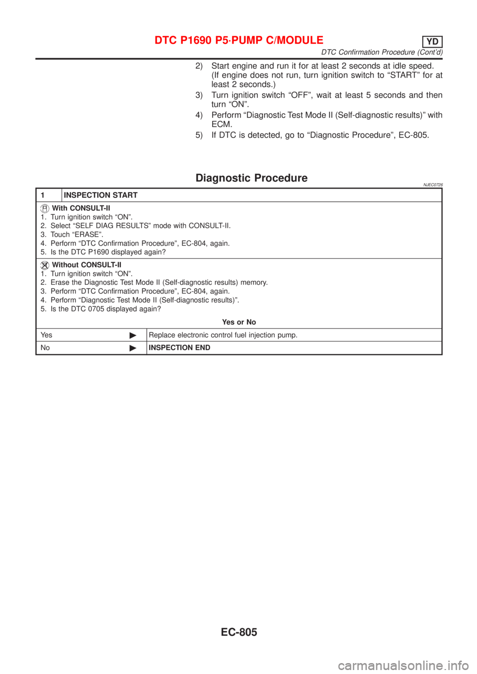
2) Start engine and run it for at least 2 seconds at idle speed.
(If engine does not run, turn ignition switch to ªSTARTº for at
least 2 seconds.)
3) Turn ignition switch ªOFFº, wait at least 5 seconds and then
turn ªONº.
4) Perform ªDiagnostic Test Mode II (Self-diagnostic results)º with
ECM.
5) If DTC is detected, go to ªDiagnostic Procedureº, EC-805.
Diagnostic ProcedureNJEC0726
1 INSPECTION START
With CONSULT-II
1. Turn ignition switch ªONº.
2. Select ªSELF DIAG RESULTSº mode with CONSULT-II.
3. Touch ªERASEº.
4. Perform ªDTC Confirmation Procedureº, EC-804, again.
5. Is the DTC P1690 displayed again?
Without CONSULT-II
1. Turn ignition switch ªONº.
2. Erase the Diagnostic Test Mode II (Self-diagnostic results) memory.
3. Perform ªDTC Confirmation Procedureº, EC-804, again.
4. Perform ªDiagnostic Test Mode II (Self-diagnostic results)º.
5. Is the DTC 0705 displayed again?
YesorNo
Ye s©Replace electronic control fuel injection pump.
No©INSPECTION END
DTC P1690 P5´PUMP C/MODULEYD
DTC Confirmation Procedure (Cont'd)
EC-805
Page 1550 of 2898

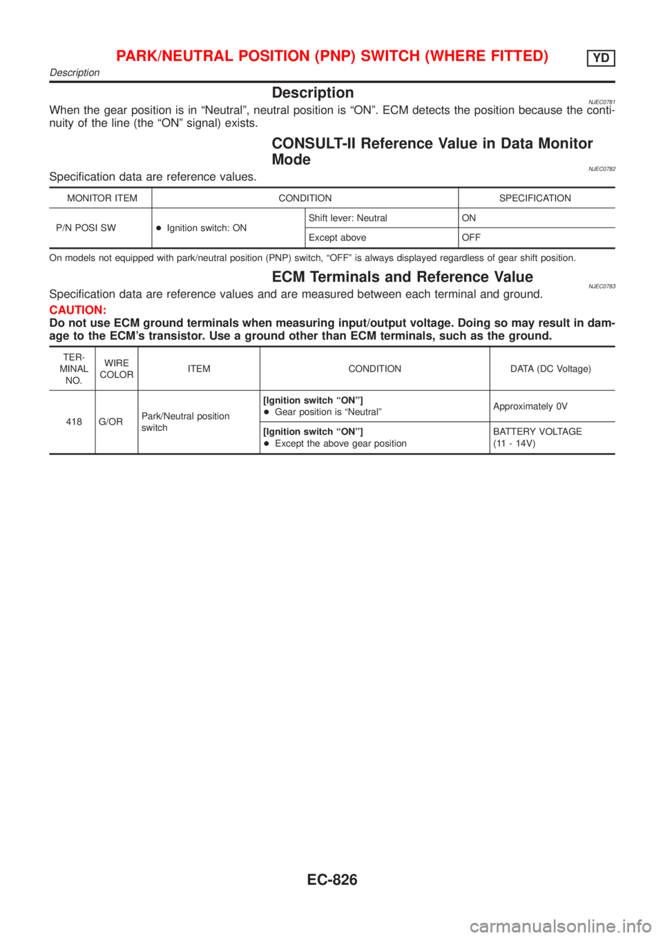
DescriptionNJEC0781When the gear position is in ªNeutralº, neutral position is ªONº. ECM detects the position because the conti-
nuity of the line (the ªONº signal) exists.
CONSULT-II Reference Value in Data Monitor
Mode
NJEC0782Specification data are reference values.
MONITOR ITEM CONDITION SPECIFICATION
P/N POSI SW+Ignition switch: ONShift lever: Neutral ON
Except above OFF
On models not equipped with park/neutral position (PNP) switch, ªOFFº is always displayed regardless of gear shift position.
ECM Terminals and Reference ValueNJEC0783Specification data are reference values and are measured between each terminal and ground.
CAUTION:
Do not use ECM ground terminals when measuring input/output voltage. Doing so may result in dam-
age to the ECM's transistor. Use a ground other than ECM terminals, such as the ground.
TER-
MINAL
NO.WIRE
COLORITEM CONDITION DATA (DC Voltage)
418 G/ORPark/Neutral position
switch[Ignition switch ªONº]
+Gear position is ªNeutralºApproximately 0V
[Ignition switch ªONº]
+Except the above gear positionBATTERY VOLTAGE
(11 - 14V)
PARK/NEUTRAL POSITION (PNP) SWITCH (WHERE FITTED)YD
Description
EC-826