2001 NISSAN ALMERA display
[x] Cancel search: displayPage 1702 of 2898
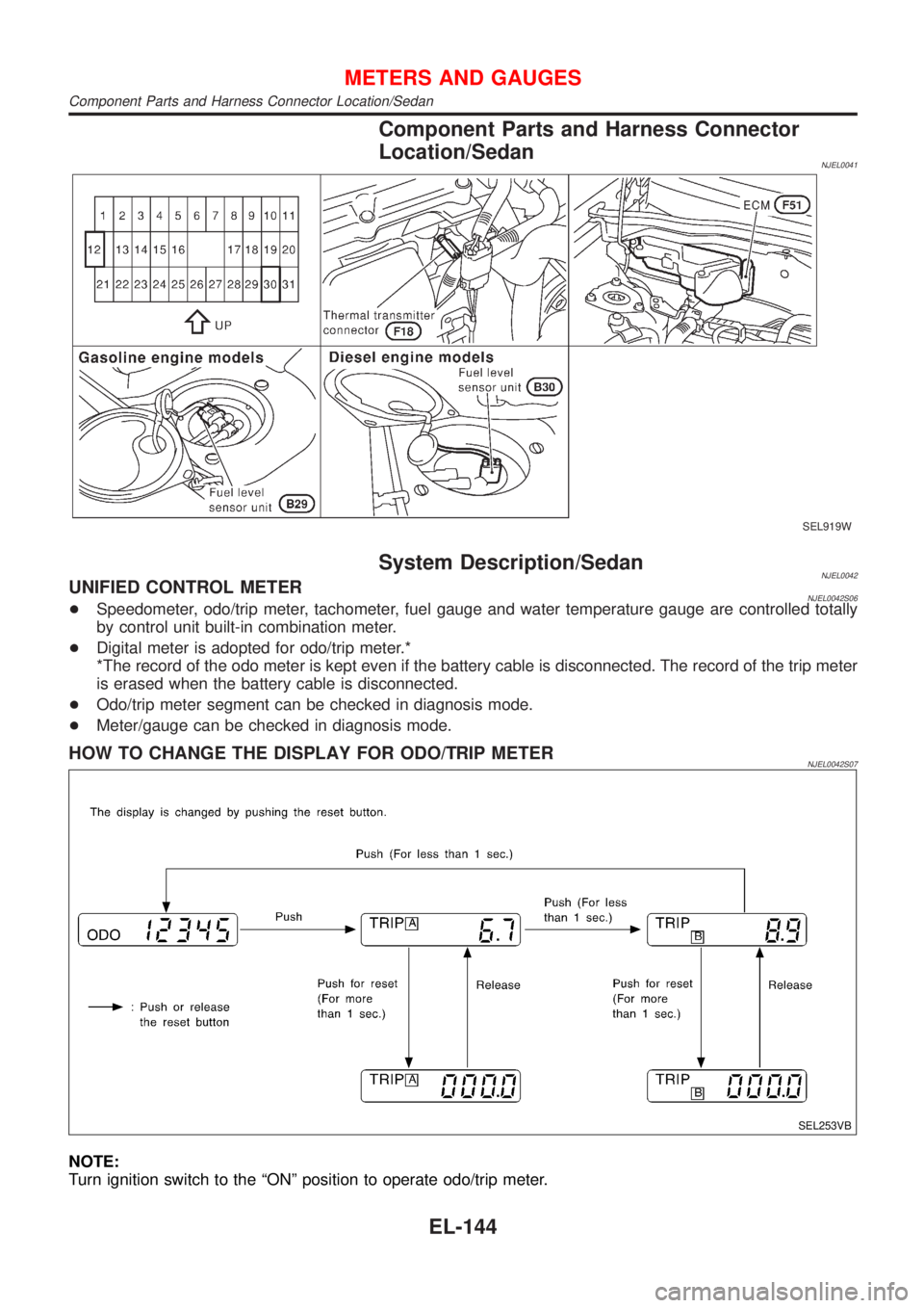
Component Parts and Harness Connector
Location/Sedan
NJEL0041
SEL919W
System Description/SedanNJEL0042UNIFIED CONTROL METERNJEL0042S06+Speedometer, odo/trip meter, tachometer, fuel gauge and water temperature gauge are controlled totally
by control unit built-in combination meter.
+Digital meter is adopted for odo/trip meter.*
*The record of the odo meter is kept even if the battery cable is disconnected. The record of the trip meter
is erased when the battery cable is disconnected.
+Odo/trip meter segment can be checked in diagnosis mode.
+Meter/gauge can be checked in diagnosis mode.
HOW TO CHANGE THE DISPLAY FOR ODO/TRIP METERNJEL0042S07
SEL253VB
NOTE:
Turn ignition switch to the ªONº position to operate odo/trip meter.
METERS AND GAUGES
Component Parts and Harness Connector Location/Sedan
EL-144
Page 1703 of 2898
![NISSAN ALMERA 2001 Service Manual POWER SUPPLY AND GROUND CIRCUITNJEL0042S08Power is supplied at all times
+through 10A fuse [No. 12, located in the fuse block (J/B)]
+to combination meter terminal 18 (with tachometer) or 21 (without NISSAN ALMERA 2001 Service Manual POWER SUPPLY AND GROUND CIRCUITNJEL0042S08Power is supplied at all times
+through 10A fuse [No. 12, located in the fuse block (J/B)]
+to combination meter terminal 18 (with tachometer) or 21 (without](/manual-img/5/57348/w960_57348-1702.png)
POWER SUPPLY AND GROUND CIRCUITNJEL0042S08Power is supplied at all times
+through 10A fuse [No. 12, located in the fuse block (J/B)]
+to combination meter terminal 18 (with tachometer) or 21 (without tachometer).
With the ignition switch in the ON or START position, power is supplied
+through 10A fuse [No. 30, located in the fuse block (J/B)]
+to combination meter terminal 17 (with tachometer) or 22 (without tachometer).
Ground is supplied
+through body grounds M28 and M67
+to combination meter terminal 24 (with tachometer) or 23 (without tachometer).
WATER TEMPERATURE GAUGENJEL0042S01The water temperature gauge indicates the engine coolant temperature. The reading on the gauge is based
on the resistance of the thermal transmitter.
As the temperature of the coolant increases, the resistance of the thermal transmitter decreases. A variable
ground is supplied to terminal 19 (with tachometer) or 34 (without tachometer) of the combination meter for
the water temperature gauge. The needle on the gauge moves from ªCº to ªHº.
TACHOMETERNJEL0042S02The tachometer indicates engine speed in revolutions per minute (rpm).
The tachometer is regulated by a signal
+from terminal 32 (Gasoline engine models) or 439 (Diesel engine models) of the ECM
+to combination meter terminal 21 for the tachometer.
FUEL GAUGENJEL0042S03The fuel gauge indicates the approximate fuel level in the fuel tank.
The fuel gauge is regulated by a variable ground signal supplied
+from body grounds B9, B21 and B308
+through terminal 1 (Gasoline engine models) or 3 (Diesel engine models) of the fuel level sensor unit and
+through terminal 4 (Gasoline engine models) or 1 (Diesel engine models) of the fuel level sensor unit
+to combination meter terminal 20 (with tachometer) or 35 (without tachometer) for the fuel gauge.
SPEEDOMETERNJEL0042S04The combination meter provides a voltage signal to the vehicle speed sensor for the speedometer.
The voltage is supplied
+from combination meter terminal 23 (with tachometer) or 37 (without tachometer) for the speedometer
+to terminal 1 of the vehicle speed sensor.
The speedometer converts the voltage into the vehicle speed displayed.
METERS AND GAUGES
System Description/Sedan (Cont'd)
EL-145
Page 1722 of 2898
Component Parts and Harness Connector
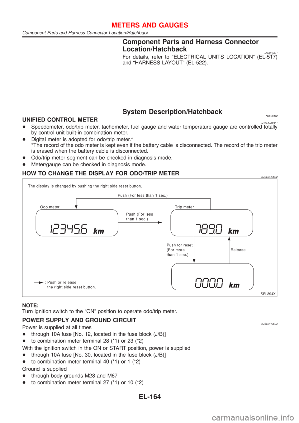
Location/Hatchback
=NJEL0441For details, refer to ªELECTRICAL UNITS LOCATIONº (EL-517)
and ªHARNESS LAYOUTº (EL-522).
System Description/HatchbackNJEL0442UNIFIED CONTROL METERNJEL0442S01+Speedometer, odo/trip meter, tachometer, fuel gauge and water temperature gauge are controlled totally
by control unit built-in combination meter.
+Digital meter is adopted for odo/trip meter.*
*The record of the odo meter is kept even if the battery cable is disconnected. The record of the trip meter
is erased when the battery cable is disconnected.
+Odo/trip meter segment can be checked in diagnosis mode.
+Meter/gauge can be checked in diagnosis mode.
HOW TO CHANGE THE DISPLAY FOR ODO/TRIP METERNJEL0442S02
SEL394X
NOTE:
Turn ignition switch to the ªONº position to operate odo/trip meter.
POWER SUPPLY AND GROUND CIRCUITNJEL0442S03Power is supplied at all times
+through 10A fuse [No. 12, located in the fuse block (J/B)]
+to combination meter terminal 28 (*1) or 23 (*2)
With the ignition switch in the ON or START position, power is supplied
+through 10A fuse [No. 30, located in the fuse block (J/B)]
+to combination meter terminal 40 (*1) or 1 (*2)
Ground is supplied
+through body grounds M28 and M67
+to combination meter terminal 27 (*1) or 10 (*2)
METERS AND GAUGES
Component Parts and Harness Connector Location/Hatchback
EL-164
Page 1723 of 2898
WATER TEMPERATURE GAUGENJEL0442S04The water temperature gauge indicates the engine coolant temperature. The reading on the gauge is based
on the resistance of the thermal transmitter.
As the temperature of the coolant increases, the resistance of the thermal transmitter decreases. A variable
ground is supplied to terminal 32 (*1) or 20 (*2) of the combination meter for the water temperature gauge.
The needle on the gauge moves from ªCº to ªHº.
TACHOMETERNJEL0442S05The tachometer indicates engine speed in revolutions per minute (rpm).
The tachometer is regulated by a signal
+from terminal 32 (Gasoline engine models) or 439 (Diesel engine models) of the ECM
+to combination meter terminal 30 (*1) or 22 (*2) for the tachometer.
FUEL GAUGENJEL0442S06The fuel gauge indicates the approximate fuel level in the fuel tank.
The fuel gauge is regulated by a variable ground signal supplied
+from body grounds M28 and M67
+through terminals 26 and 27 (*1) or 9 and 10 (*2) of combination meter,
+through terminal 1 of the fuel level sensor unit and
+through terminal 4 of the fuel level sensor unit
+to combination meter terminal 31 (*1) or 24 (*2) for the fuel gauge.
SPEEDOMETERNJEL0442S07The combination meter provides a voltage signal to the vehicle speed sensor for the speedometer.
The voltage is supplied
+from combination meter terminal 29 (*1) or 5 (*2) for the speedometer
+to terminal 1 of the vehicle speed sensor.
Ground is supplied
+from body grounds M28 and M67
+through terminals 25 and 27 (*1) or 10 and 11 (*2) of combination meter
+to teminal 2 of the vehicle speed sensor.
The speedometer converts the voltage into the vehicle speed displayed.
*1: Models before VIN No. Ð N16U0135126
*2: Models after VIN No. Ð N16U0135126
METERS AND GAUGES
System Description/Hatchback (Cont'd)
EL-165
Page 1731 of 2898
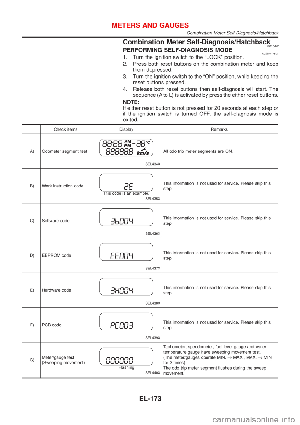
Combination Meter Self-Diagnosis/HatchbackNJEL0447PERFORMING SELF-DIAGNOSIS MODENJEL0447S011. Turn the ignition switch to the ªLOCKº position.
2. Press both reset buttons on the combination meter and keep
them depressed.
3. Turn the ignition switch to the ªONº position, while keeping the
reset buttons pressed.
4. Release both reset buttons then self-diagnosis will start. The
sequence (A to L) is activated by press the either reset buttons.
NOTE:
If either reset button is not pressed for 20 seconds at each step or
if the ignition switch is turned OFF, the self-diagnosis mode is
exited.
Check items Display Remarks
A) Odometer segment test
SEL434X
All odo trip meter segments are ON.
B) Work instruction code
SEL435X
This information is not used for service. Please skip this
step.
C) Software code
SEL436X
This information is not used for service. Please skip this
step.
D) EEPROM code
SEL437X
This information is not used for service. Please skip this
step.
E) Hardware code
SEL438X
This information is not used for service. Please skip this
step.
F) PCB code
SEL439X
This information is not used for service. Please skip this
step.
G)Meter/gauge test
(Sweeping movement)
SEL440X
Tachometer, speedometer, fuel level gauge and water
temperature gauge have sweeping movement test.
(The meter/gauges operate MIN.®MAX., MAX.®MIN.
for 2 times)
The odo trip meter segment flushes during the sweep
movement.
METERS AND GAUGES
Combination Meter Self-Diagnosis/Hatchback
EL-173
Page 1732 of 2898
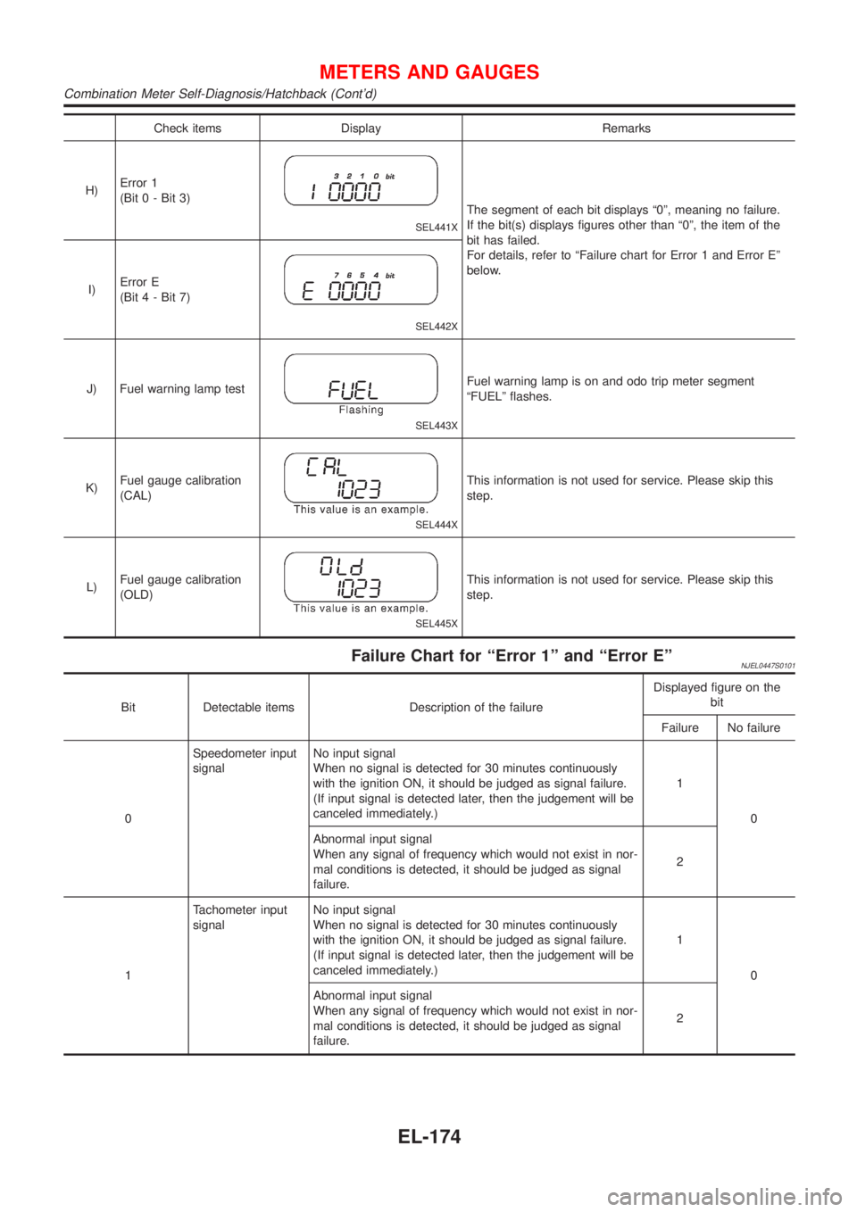
Check items Display Remarks
H)Error 1
(Bit 0 - Bit 3)
SEL441X
The segment of each bit displays ª0º, meaning no failure.
If the bit(s) displays figures other than ª0º, the item of the
bit has failed.
For details, refer to ªFailure chart for Error 1 and Error Eº
below.
I)Error E
(Bit 4 - Bit 7)
SEL442X
J) Fuel warning lamp test
SEL443X
Fuel warning lamp is on and odo trip meter segment
ªFUELº flashes.
K)Fuel gauge calibration
(CAL)
SEL444X
This information is not used for service. Please skip this
step.
L)Fuel gauge calibration
(OLD)
SEL445X
This information is not used for service. Please skip this
step.
Failure Chart for ªError 1º and ªError EºNJEL0447S0101
Bit Detectable items Description of the failureDisplayed figure on the
bit
Failure No failure
0Speedometer input
signalNo input signal
When no signal is detected for 30 minutes continuously
with the ignition ON, it should be judged as signal failure.
(If input signal is detected later, then the judgement will be
canceled immediately.)1
0
Abnormal input signal
When any signal of frequency which would not exist in nor-
mal conditions is detected, it should be judged as signal
failure.2
1Tachometer input
signalNo input signal
When no signal is detected for 30 minutes continuously
with the ignition ON, it should be judged as signal failure.
(If input signal is detected later, then the judgement will be
canceled immediately.)1
0
Abnormal input signal
When any signal of frequency which would not exist in nor-
mal conditions is detected, it should be judged as signal
failure.2
METERS AND GAUGES
Combination Meter Self-Diagnosis/Hatchback (Cont'd)
EL-174
Page 1733 of 2898
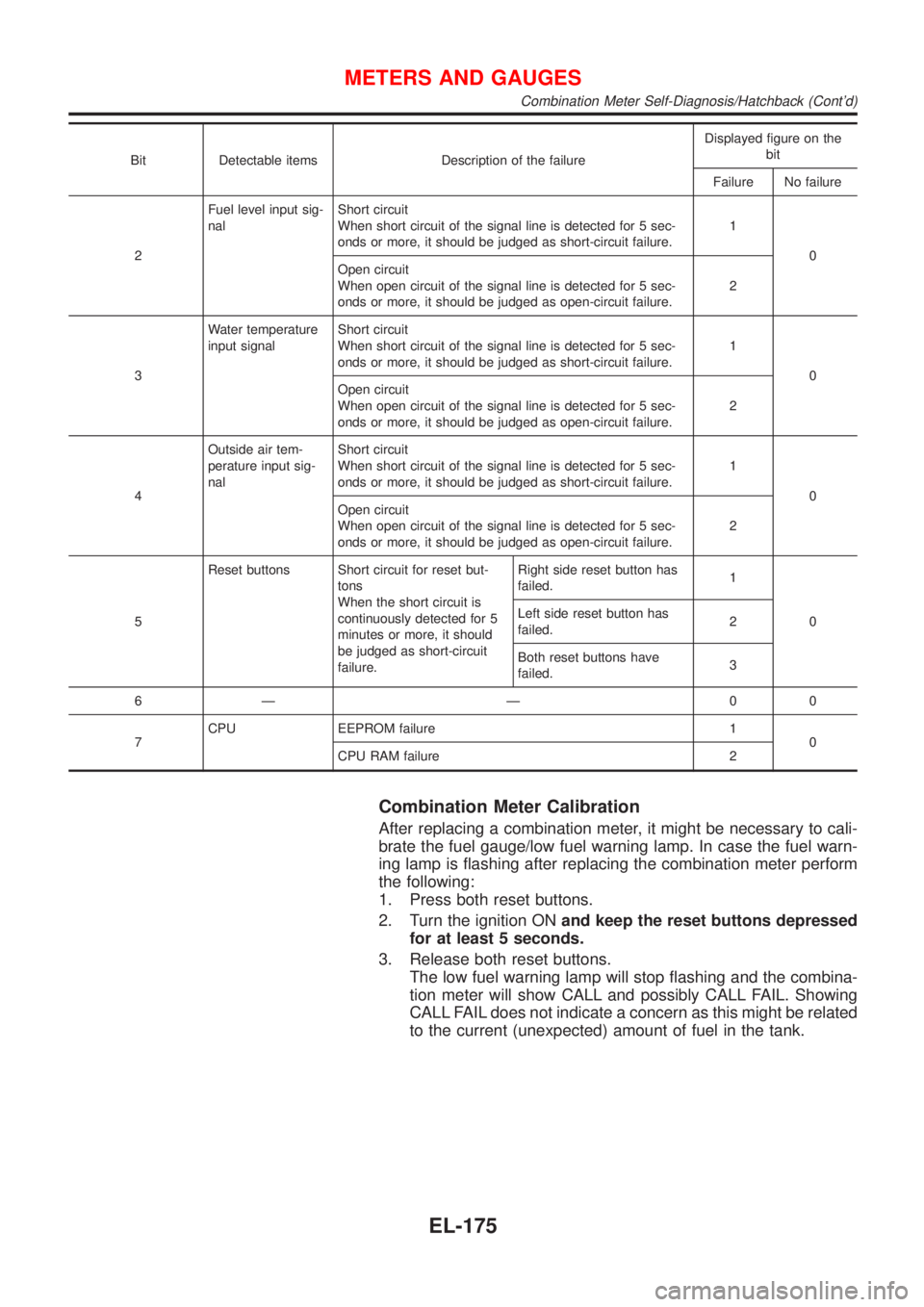
Bit Detectable items Description of the failureDisplayed figure on the
bit
Failure No failure
2Fuel level input sig-
nalShort circuit
When short circuit of the signal line is detected for 5 sec-
onds or more, it should be judged as short-circuit failure.1
0
Open circuit
When open circuit of the signal line is detected for 5 sec-
onds or more, it should be judged as open-circuit failure.2
3Water temperature
input signalShort circuit
When short circuit of the signal line is detected for 5 sec-
onds or more, it should be judged as short-circuit failure.1
0
Open circuit
When open circuit of the signal line is detected for 5 sec-
onds or more, it should be judged as open-circuit failure.2
4Outside air tem-
perature input sig-
nalShort circuit
When short circuit of the signal line is detected for 5 sec-
onds or more, it should be judged as short-circuit failure.1
0
Open circuit
When open circuit of the signal line is detected for 5 sec-
onds or more, it should be judged as open-circuit failure.2
5Reset buttons Short circuit for reset but-
tons
When the short circuit is
continuously detected for 5
minutes or more, it should
be judged as short-circuit
failure.Right side reset button has
failed.1
0 Left side reset button has
failed.2
Both reset buttons have
failed.3
6Ð Ð 00
7CPU EEPROM failure 1
0
CPU RAM failure 2
Combination Meter Calibration
After replacing a combination meter, it might be necessary to cali-
brate the fuel gauge/low fuel warning lamp. In case the fuel warn-
ing lamp is flashing after replacing the combination meter perform
the following:
1. Press both reset buttons.
2. Turn the ignition ONand keep the reset buttons depressed
for at least 5 seconds.
3. Release both reset buttons.
The low fuel warning lamp will stop flashing and the combina-
tion meter will show CALL and possibly CALL FAIL. Showing
CALL FAIL does not indicate a concern as this might be related
to the current (unexpected) amount of fuel in the tank.
METERS AND GAUGES
Combination Meter Self-Diagnosis/Hatchback (Cont'd)
EL-175
Page 1816 of 2898
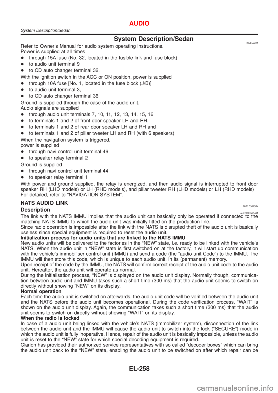
System Description/Sedan=NJEL0381Refer to Owner's Manual for audio system operating instructions.
Power is supplied at all times
+through 15A fuse (No. 32, located in the fusible link and fuse block)
+to audio unit terminal 9
+to CD auto changer terminal 32.
With the ignition switch in the ACC or ON position, power is supplied
+through 10A fuse [No. 1, located in the fuse block (J/B)]
+to audio unit terminal 3,
+to CD auto changer terminal 36
Ground is supplied through the case of the audio unit.
Audio signals are supplied
+through audio unit terminals 7, 10, 11, 12, 13, 14, 15, 16
+to terminals 1 and 2 of front door speaker LH and RH,
+to terminals 1 and 2 of rear door speaker LH and RH and
+to terminals 1 and 2 of pillar tweeter LH and RH (with 6 speakers)
When the navigation system is triggered,
power is supplied
+through navi control unit terminal 46
+to speaker relay terminal 2
Ground is supplied
+through navi control unit terminal 44
+to speaker relay terminal 1
With power and ground supplied, the relay is energized, and then audio signal is interrupted to front door
speaker RH (LHD models) or LH (RHD models), and pillar tweeter RH (LHD models) or LH (RHD models)
For detailed, refer to ªNAVIGATION SYSTEMº.
NATS AUDIO LINKNJEL0381S04DescriptionNJEL0381S0401The link with the NATS IMMU implies that the audio unit can basically only be operated if connected to the
matching NATS IMMU to which the audio unit was initially fitted on the production line.
Since radio operation is impossible after the link with the NATS is disrupted theft of the audio unit is basically
useless since special equipment is required to reset the audio unit.
Initialization process for audio units that are linked to the NATS IMMU
New audio units will be delivered to the factories in the ªNEWº state, i.e. ready to be linked with the vehicle's
NATS. When the audio unit in ªNEWº state is first switched on at the factory, it will start up communication
with the vehicle's immobiliser control unit (IMMU) and send a code (the ªaudio unit Codeº) to the IMMU. The
IMMU will then store this code, which is unique to each audio unit, in its (permanent) memory.
Upon receipt of the code by the IMMU, the NATS will confirm correct receipt of the audio unit code to the audio
unit. Hereafter, the audio unit will operate as normal.
During the initialisation process, ªNEWº is displayed on the audio unit display. Normally though, communica-
tion between audio unit and IMMU takes such a short time (300 ms) that the audio unit seems to switch on
directly without showing ªNEWº on its display.
Normal operation
Each time the audio unit is switched on afterwards, the audio unit code will be verified between the audio unit
and the NATS before the audio unit becomes operational. During the code verification process, ªWAITº is
shown on the audio unit display. Again, the communication takes such a short time (300 ms) that the audio
unit seems to switch on directly without showing ªWAITº on its display.
When the radio is locked
In case of a audio unit being linked with the vehicle's NATS (immobilizer system), disconnection of the link
between the audio unit and the IMMU will cause the audio unit to switch into the lock (ªSECUREº) mode in
which the audio unit is fully inoperative. Hence, repair of the audio unit is basically impossible, unless the audio
unit is reset to the ªNEWº state for which special decoding equipment is required.
Clarion has provided their authorized service representatives with so called ªdecoder boxesº which can bring
the audio unit back to the ªNEWº state, enabling the audio unit to be switched on after which repair can be
AUDIO
System Description/Sedan
EL-258