2001 NISSAN ALMERA light
[x] Cancel search: lightPage 1975 of 2898
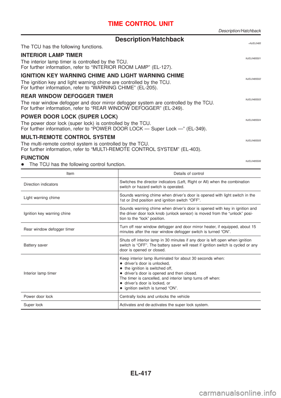
Description/Hatchback=NJEL0485The TCU has the following functions.
INTERIOR LAMP TIMERNJEL0485S01The interior lamp timer is controlled by the TCU.
For further information, refer to ªINTERIOR ROOM LAMPº (EL-127).
IGNITION KEY WARNING CHIME AND LIGHT WARNING CHIMENJEL0485S02The ignition key and light warning chime are controlled by the TCU.
For further information, refer to ªWARNING CHIMEº (EL-205).
REAR WINDOW DEFOGGER TIMERNJEL0485S03The rear window defogger and door mirror defogger system are controlled by the TCU.
For further information, refer to ªREAR WINDOW DEFOGGERº (EL-249).
POWER DOOR LOCK (SUPER LOCK)NJEL0485S04The power door lock (super lock) is controlled by the TCU.
For further information, refer to ªPOWER DOOR LOCK Ð Super Lock к (EL-349).
MULTI-REMOTE CONTROL SYSTEMNJEL0485S05The multi-remote control system is controlled by the TCU.
For further information, refer to ªMULTI-REMOTE CONTROL SYSTEMº (EL-403).
FUNCTIONNJEL0485S06+The TCU has the following control function.
Item Details of control
Direction indicatorsSwitches the director indicators (Left, Right or All) when the combination
switch or hazard switch is operated.
Light warning chimeSounds warning chime when driver's door is opened with light switch in the
1st or 2nd position and ignition switch ªOFFº.
Ignition key warning chineSounds warning chime when driver's door is opened with key in ignition and
the driver door lock knob (unlock sensor) is moved from the ªunlockº posi-
tion to the ªlockº position.
Rear window defogger timerTurn off rear window defogger and door mirror heater, if equipped, about 15
minutes after the rear window defogger switch is turned ªONº.
Battery saverShuts off interior lamp in 30 minutes if any door is left open when ignition
switch is ªOFFº. The battery saver will reset if ignition switch is cycled or any
door is opened or closed.
Interior lamp timerKeep interior lamp illuminated for about 30 seconds when:
+driver's door is unlocked,
+the ignition is switched off,
+driver's door is opened and then closed.
The timer is cancelled, and interior lamp turns off when:
+driver's door is locked, or
+ignition switch is turned ªONº.
Power door lock Centrally locks and unlocks the vehicle
Super lock Activates and de-activates the super lock system.
TIME CONTROL UNIT
Description/Hatchback
EL-417
Page 1977 of 2898

USER ACTION TCU Reaction COMPONENT TESTED
Lighting switch turned 1st position or 2nd
position from offHazard flash once Tail lamp signal
Key put in ignition from out Hazard flash once Key in detect signal
Door lock/unlock switch is pressed Hazard flash once Central door lock/unlock signal
*) Hazard may flash a second time because of Driver's door status signal change. The min. delay time between flash actions is 100
ms.
In case the system does not operate as described above, check the concerned circuit for open or short. After
completion, the Diagnostic Mode can be switched off by pressing the rear defogger switch or by turning the
ignition to ªONº. The hazard lamp will flash at 3 Hz for 3 seconds to confirm that Diagnostic Mode has been
switched off.
TIME CONTROL UNIT
Trouble Diagnoses/Hatchback (Cont'd)
EL-419
Page 1981 of 2898
System Description=NJEL0407NATS (Nissan Anti-Theft System) has the following immobilizer functions:
+Since only NATS ignition keys, whose ID nos. have been registered into the ECM and IMMU of NATS,
allow the engine to run, operation of a stolen vehicle without a NATS registered key is prevented by NATS.
That is to say, NATS will immobilize the engine if someone tries to start it without the registered key of
NATS.
+This version of NATS has dongle unit to improve its anti-theft performance (RHD models for Europe).
Dongle unit has its own ID which is registered into NATS IMMU. So if dongle unit is replaced, initialization
must be carried out.
+When malfunction of dongle unit is detected:
The security indicator lamp illuminates for about 15 minutes after ignition switch is turned to ON.
þ When dongle unit has a malfunction and the indicator lamp is illuminated, engine can not be started.
However engine can be started only one time when security indicator lamp turns off in about 15 minutes
after ignition switch is turned to ON.
+All of the originally supplied ignition key IDs have been NATS registered.
If requested by the vehicle owner, a maximum of five key IDs can be registered into the NATS compo-
nents.
+The security indicator blinks when the ignition switch is in ªOFFº or ªACCº position. Therefore, NATS warns
outsiders that the vehicle is equipped with the anti-theft system.
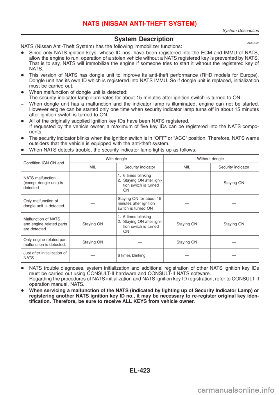
+When NATS detects trouble, the security indicator lamp lights up as follows.
Condition IGN ON andWith dongle Without dongle
MIL Security indicator MIL Security indicator
NATS malfunction
(except dongle unit) is
detectedÐ1. 6 times blinking
2. Staying ON after igni-
tion switch is turned
ONÐ Staying ON
Only malfunction of
dongle unit is detected.ÐStaying ON for about 15
minutes after ignition
switch is turned ONÐÐ
Malfunction of NATS
and engine related parts
are detected.Staying ON1. 6 times blinking
2. Staying ON after igni-
tion switch is turned
ONStaying ON Staying ON
Only engine related part
malfunction is detected.Staying ON Ð Staying ON Ð
Just after initialization of
NATSÐ 6 times blinking Ð Ð
+NATS trouble diagnoses, system initialization and additional registration of other NATS ignition key IDs
must be carried out using CONSULT-II hardware and CONSULT-II NATS software.
Regarding the procedures of NATS initialization and NATS ignition key ID registration, refer to CONSULT-II
operation manual, NATS.
+When servicing a malfunction of the NATS (indicated by lighting up of Security Indicator Lamp) or
registering another NATS ignition key ID no., it may be necessary to re-register original key iden-
tification. Therefore, be sure to receive ALL KEYS from vehicle owner.
NATS (NISSAN ANTI-THEFT SYSTEM)
System Description
EL-423
Page 1991 of 2898
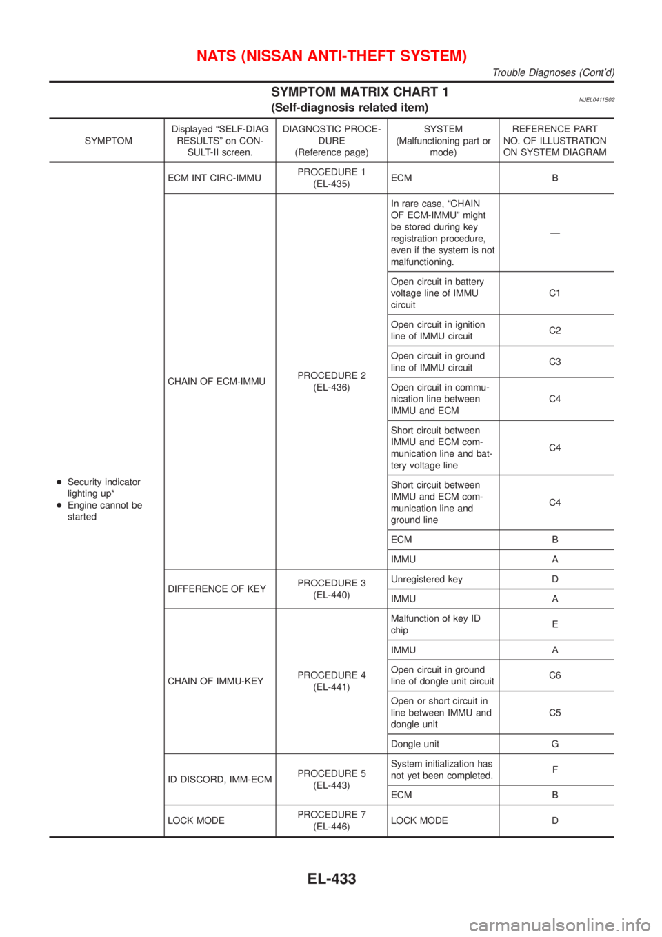
SYMPTOM MATRIX CHART 1NJEL0411S02(Self-diagnosis related item)
SYMPTOMDisplayed ªSELF-DIAG
RESULTSº on CON-
SULT-II screen.DIAGNOSTIC PROCE-
DURE
(Reference page)SYSTEM
(Malfunctioning part or
mode)REFERENCE PART
NO. OF ILLUSTRATION
ON SYSTEM DIAGRAM
+Security indicator
lighting up*
+Engine cannot be
startedECM INT CIRC-IMMUPROCEDURE 1
(EL-435)ECM B
CHAIN OF ECM-IMMUPROCEDURE 2
(EL-436)In rare case, ªCHAIN
OF ECM-IMMUº might
be stored during key
registration procedure,
even if the system is not
malfunctioning.Ð
Open circuit in battery
voltage line of IMMU
circuitC1
Open circuit in ignition
line of IMMU circuitC2
Open circuit in ground
line of IMMU circuitC3
Open circuit in commu-
nication line between
IMMU and ECMC4
Short circuit between
IMMU and ECM com-
munication line and bat-
tery voltage lineC4
Short circuit between
IMMU and ECM com-
munication line and
ground lineC4
ECM B
IMMU A
DIFFERENCE OF KEYPROCEDURE 3
(EL-440)Unregistered key D
IMMU A
CHAIN OF IMMU-KEYPROCEDURE 4
(EL-441)Malfunction of key ID
chipE
IMMU A
Open circuit in ground
line of dongle unit circuitC6
Open or short circuit in
line between IMMU and
dongle unitC5
Dongle unit G
ID DISCORD, IMM-ECMPROCEDURE 5
(EL-443)System initialization has
not yet been completed.F
ECM B
LOCK MODEPROCEDURE 7
(EL-446)LOCK MODE D
NATS (NISSAN ANTI-THEFT SYSTEM)
Trouble Diagnoses (Cont'd)
EL-433
Page 1992 of 2898
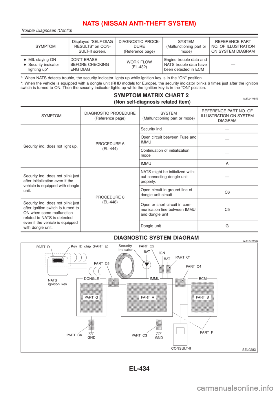
SYMPTOMDisplayed ªSELF-DIAG
RESULTSº on CON-
SULT-II screen.DIAGNOSTIC PROCE-
DURE
(Reference page)SYSTEM
(Malfunctioning part or
mode)REFERENCE PART
NO. OF ILLUSTRATION
ON SYSTEM DIAGRAM
+MIL staying ON
+Security indicator
lighting up*DON'T ERASE
BEFORE CHECKING
ENG DIAGWORK FLOW
(EL-432)Engine trouble data and
NATS trouble data have
been detected in ECMÐ
*: When NATS detects trouble, the security indicator lights up while ignition key is in the ªONº position.
*: When the vehicle is equipped with a dongle unit (RHD models for Europe), the security indicator blinks 6 times just after the ignition
switch is turned to ON. Then the security indicator lights up while the ignition key is in the ªONº position.
SYMPTOM MATRIX CHART 2NJEL0411S03(Non self-diagnosis related item)
SYMPTOMDIAGNOSTIC PROCEDURE
(Reference page)SYSTEM
(Malfunctioning part or mode)REFERENCE PART NO. OF
ILLUSTRATION ON SYSTEM
DIAGRAM
Security ind. does not light up.PROCEDURE 6
(EL-444)Security ind. Ð
Open circuit between Fuse and
IMMUÐ
Continuation of initialization
modeÐ
IMMU A
Security ind. does not blink just
after initialization even if the
vehicle is equipped with dongle
unit.
PROCEDURE 8
(EL-448)NATS might be initialized with-
out connecting dongle unit
properly.Ð
Open circuit in ground line of
dongle unit circuitC6
Security ind. does not blink just
after ignition switch is turned to
ON when some malfunction
related to NATS is detected
even if the vehicle is equipped
with dongle unit.Open or short circuit in com-
munication line between IMMU
and dongle unitC5
Dongle unit G
DIAGNOSTIC SYSTEM DIAGRAMNJEL0411S04
SEL028X
NATS (NISSAN ANTI-THEFT SYSTEM)
Trouble Diagnoses (Cont'd)
EL-434
Page 2002 of 2898
![NISSAN ALMERA 2001 Service Manual DIAGNOSTIC PROCEDURE 6=NJEL0411S10ªSECURITY INDICATOR LAMP DOES NOT LIGHT UPº
1 CHECK FUSE
Check 10A fuse [No. 12, located in the fuse block (J/B)].
Is 10A fuse OK?
Ye s©GO TO 2.
No©Replace fuse.
NISSAN ALMERA 2001 Service Manual DIAGNOSTIC PROCEDURE 6=NJEL0411S10ªSECURITY INDICATOR LAMP DOES NOT LIGHT UPº
1 CHECK FUSE
Check 10A fuse [No. 12, located in the fuse block (J/B)].
Is 10A fuse OK?
Ye s©GO TO 2.
No©Replace fuse.](/manual-img/5/57348/w960_57348-2001.png)
DIAGNOSTIC PROCEDURE 6=NJEL0411S10ªSECURITY INDICATOR LAMP DOES NOT LIGHT UPº
1 CHECK FUSE
Check 10A fuse [No. 12, located in the fuse block (J/B)].
Is 10A fuse OK?
Ye s©GO TO 2.
No©Replace fuse.
2 CHECK SECURITY INDICATOR LAMP
1. Install 10A fuse.
2. Perform initialization with CONSULT-II.
For initialization, refer to ªCONSULT-II Operation Manual NATSº.
3. Turn ignition switch OFF.
4. Start engine and turn ignition switch OFF.
5. Check the security indicator lamp lighting.
Security indicator lamp should be light up.
OK or NG
OK©INSPECTION END
NG©GO TO 3.
3 CHECK SECURITY INDICATOR LAMP POWER SUPPLY CIRCUIT
1. Disconnect security indicator lamp connector (models before VIN No. Ð N16U0135126) or Combination meter connec-
tor (models after VIN No. Ð N16U0135126).
2. Check voltage between security indicator lamp connector terminal 2 and ground (models before VIN No. Ð
N16U0135126), or Check voltage between combination meter (security indicator lamp) connector terminal 23 and
ground (models after VIN No. Ð N16U0135126).
YEL787C
OK or NG
OK©GO TO 4.
NG©Check harness for open or short between fuse and security indicator lamp (models
before VIN No. Ð N16U0135126) or Combination meter (models after VIN No. Ð
N16U0135126).
4 CHECK SECURITY INDICATOR LAMP
Check security Indicator Lamp.
Is security indicator lamp OK?
Ye s©GO TO 5.
No©Repair or replace combination meter or security indicator lamp.
NATS (NISSAN ANTI-THEFT SYSTEM)
Trouble Diagnoses (Cont'd)
EL-444
Page 2010 of 2898
SEL504X
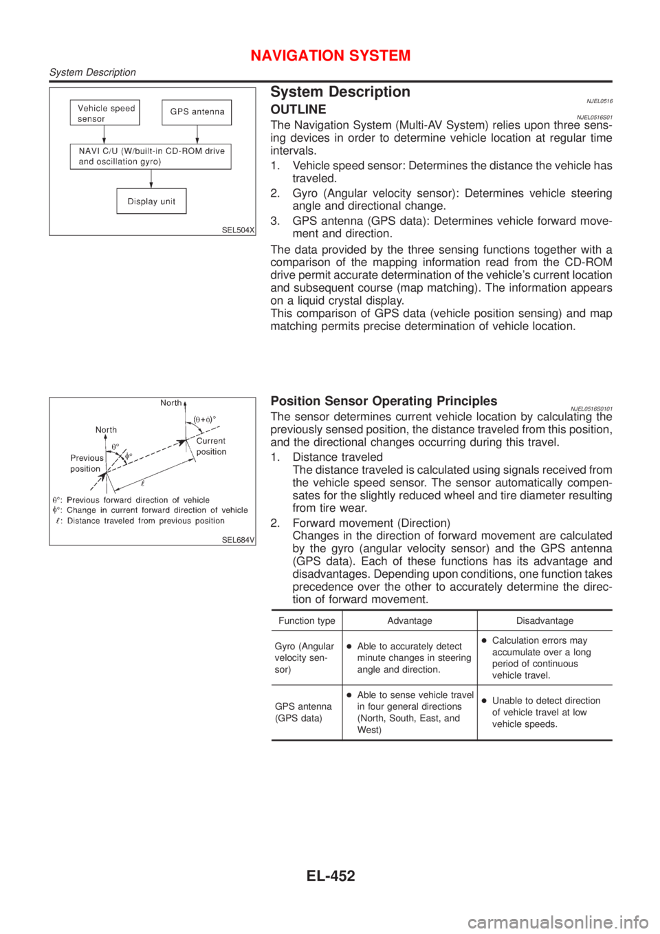
System DescriptionNJEL0516OUTLINENJEL0516S01The Navigation System (Multi-AV System) relies upon three sens-
ing devices in order to determine vehicle location at regular time
intervals.
1. Vehicle speed sensor: Determines the distance the vehicle has
traveled.
2. Gyro (Angular velocity sensor): Determines vehicle steering
angle and directional change.
3. GPS antenna (GPS data): Determines vehicle forward move-
ment and direction.
The data provided by the three sensing functions together with a
comparison of the mapping information read from the CD-ROM
drive permit accurate determination of the vehicle's current location
and subsequent course (map matching). The information appears
on a liquid crystal display.
This comparison of GPS data (vehicle position sensing) and map
matching permits precise determination of vehicle location.
SEL684V
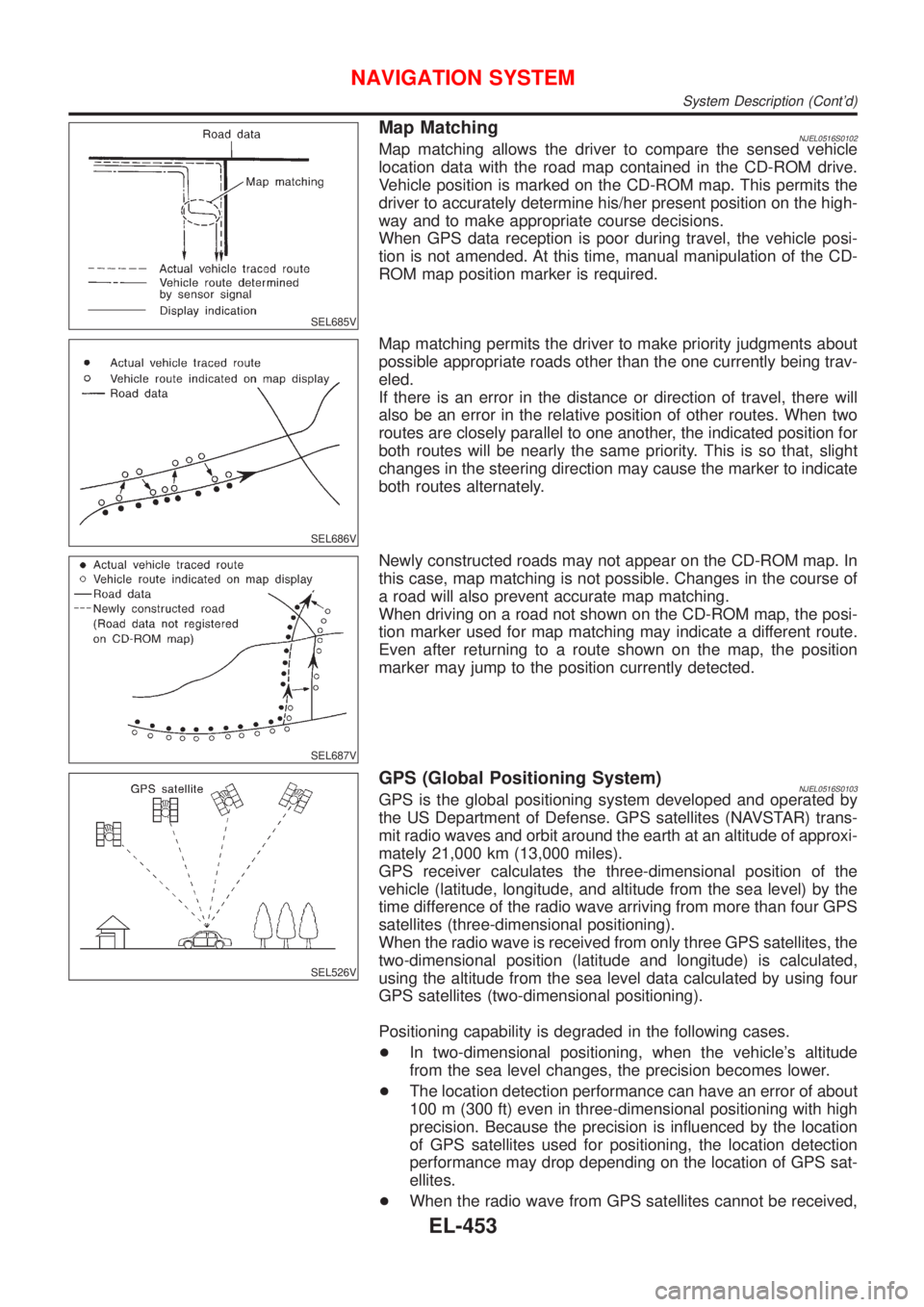
Position Sensor Operating PrinciplesNJEL0516S0101The sensor determines current vehicle location by calculating the
previously sensed position, the distance traveled from this position,
and the directional changes occurring during this travel.
1. Distance traveled
The distance traveled is calculated using signals received from
the vehicle speed sensor. The sensor automatically compen-
sates for the slightly reduced wheel and tire diameter resulting
from tire wear.
2. Forward movement (Direction)
Changes in the direction of forward movement are calculated
by the gyro (angular velocity sensor) and the GPS antenna
(GPS data). Each of these functions has its advantage and
disadvantages. Depending upon conditions, one function takes
precedence over the other to accurately determine the direc-
tion of forward movement.
Function type Advantage Disadvantage
Gyro (Angular
velocity sen-
sor)+Able to accurately detect
minute changes in steering
angle and direction.+Calculation errors may
accumulate over a long
period of continuous
vehicle travel.
GPS antenna
(GPS data)+Able to sense vehicle travel
in four general directions
(North, South, East, and
West)+Unable to detect direction
of vehicle travel at low
vehicle speeds.
NAVIGATION SYSTEM
System Description
EL-452
Page 2011 of 2898
SEL685V
Map MatchingNJEL0516S0102Map matching allows the driver to compare the sensed vehicle
location data with the road map contained in the CD-ROM drive.
Vehicle position is marked on the CD-ROM map. This permits the
driver to accurately determine his/her present position on the high-
way and to make appropriate course decisions.
When GPS data reception is poor during travel, the vehicle posi-
tion is not amended. At this time, manual manipulation of the CD-
ROM map position marker is required.
SEL686V
Map matching permits the driver to make priority judgments about
possible appropriate roads other than the one currently being trav-
eled.
If there is an error in the distance or direction of travel, there will
also be an error in the relative position of other routes. When two
routes are closely parallel to one another, the indicated position for
both routes will be nearly the same priority. This is so that, slight
changes in the steering direction may cause the marker to indicate
both routes alternately.
SEL687V
Newly constructed roads may not appear on the CD-ROM map. In
this case, map matching is not possible. Changes in the course of
a road will also prevent accurate map matching.
When driving on a road not shown on the CD-ROM map, the posi-
tion marker used for map matching may indicate a different route.
Even after returning to a route shown on the map, the position
marker may jump to the position currently detected.
SEL526V
GPS (Global Positioning System)NJEL0516S0103GPS is the global positioning system developed and operated by
the US Department of Defense. GPS satellites (NAVSTAR) trans-
mit radio waves and orbit around the earth at an altitude of approxi-
mately 21,000 km (13,000 miles).
GPS receiver calculates the three-dimensional position of the
vehicle (latitude, longitude, and altitude from the sea level) by the
time difference of the radio wave arriving from more than four GPS
satellites (three-dimensional positioning).
When the radio wave is received from only three GPS satellites, the
two-dimensional position (latitude and longitude) is calculated,
using the altitude from the sea level data calculated by using four
GPS satellites (two-dimensional positioning).
Positioning capability is degraded in the following cases.
+In two-dimensional positioning, when the vehicle's altitude
from the sea level changes, the precision becomes lower.
+The location detection performance can have an error of about
100 m (300 ft) even in three-dimensional positioning with high
precision. Because the precision is influenced by the location
of GPS satellites used for positioning, the location detection
performance may drop depending on the location of GPS sat-
ellites.
+When the radio wave from GPS satellites cannot be received,
NAVIGATION SYSTEM
System Description (Cont'd)
EL-453