2001 NISSAN ALMERA light
[x] Cancel search: lightPage 2622 of 2898
SMT600-A
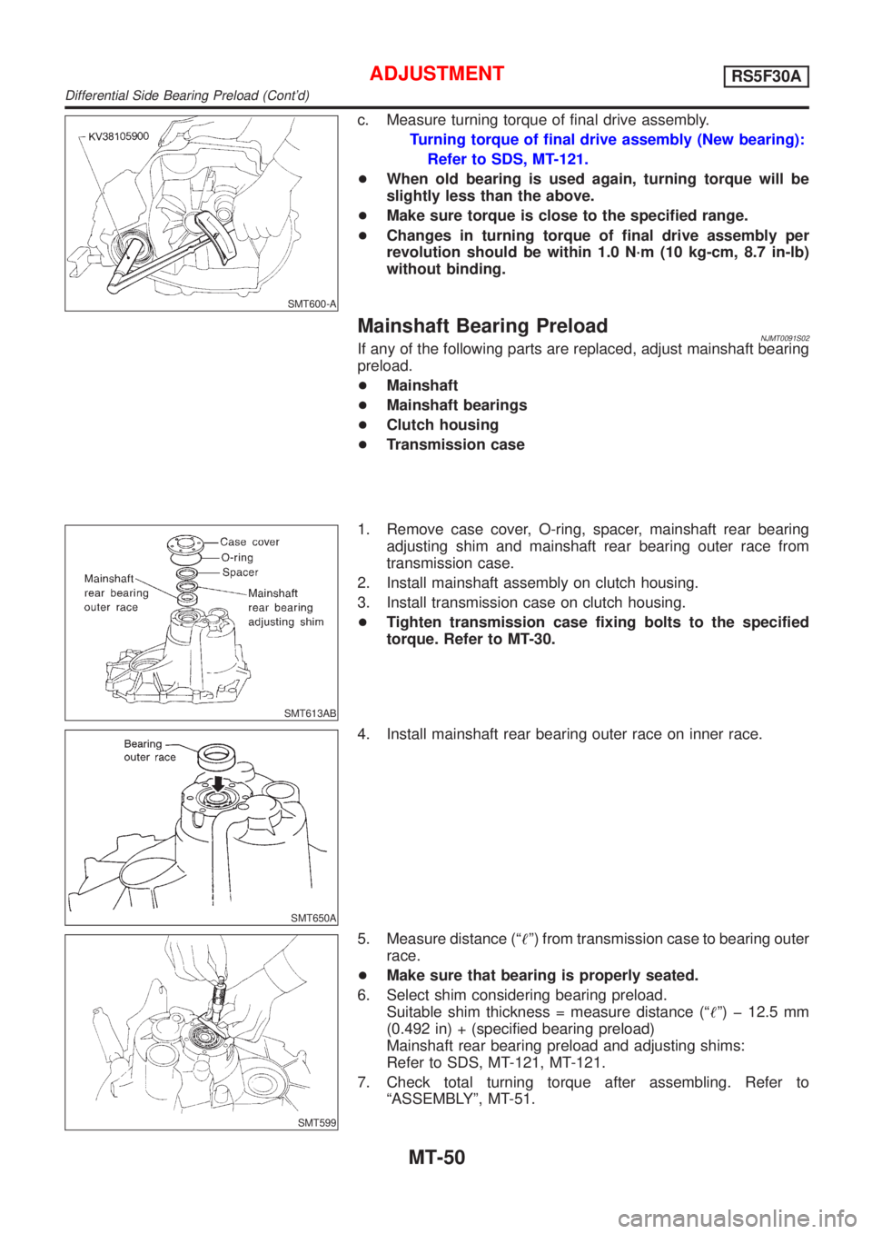
c. Measure turning torque of final drive assembly.
Turning torque of final drive assembly (New bearing):
Refer to SDS, MT-121.
+When old bearing is used again, turning torque will be
slightly less than the above.
+Make sure torque is close to the specified range.
+Changes in turning torque of final drive assembly per
revolution should be within 1.0 N´m (10 kg-cm, 8.7 in-lb)
without binding.
Mainshaft Bearing PreloadNJMT0091S02If any of the following parts are replaced, adjust mainshaft bearing
preload.
+Mainshaft
+Mainshaft bearings
+Clutch housing
+Transmission case
SMT613AB
1. Remove case cover, O-ring, spacer, mainshaft rear bearing
adjusting shim and mainshaft rear bearing outer race from
transmission case.
2. Install mainshaft assembly on clutch housing.
3. Install transmission case on clutch housing.
+Tighten transmission case fixing bolts to the specified
torque. Refer to MT-30.
SMT650A
4. Install mainshaft rear bearing outer race on inner race.
SMT599
5. Measure distance (ª!º) from transmission case to bearing outer
race.
+Make sure that bearing is properly seated.
6. Select shim considering bearing preload.
Suitable shim thickness = measure distance (ª!º) þ 12.5 mm
(0.492 in) + (specified bearing preload)
Mainshaft rear bearing preload and adjusting shims:
Refer to SDS, MT-121, MT-121.
7. Check total turning torque after assembling. Refer to
ªASSEMBLYº, MT-51.
ADJUSTMENTRS5F30A
Differential Side Bearing Preload (Cont'd)
MT-50
Page 2625 of 2898
SMT587
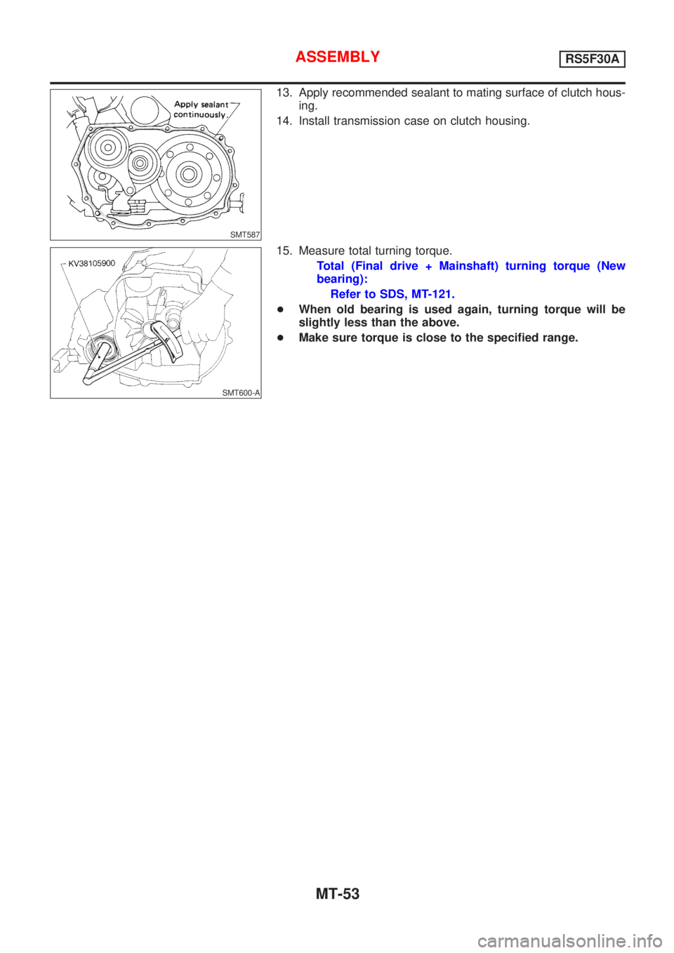
13. Apply recommended sealant to mating surface of clutch hous-
ing.
14. Install transmission case on clutch housing.
SMT600-A
15. Measure total turning torque.
Total (Final drive + Mainshaft) turning torque (New
bearing):
Refer to SDS, MT-121.
+When old bearing is used again, turning torque will be
slightly less than the above.
+Make sure torque is close to the specified range.
ASSEMBLYRS5F30A
MT-53
Page 2659 of 2898
SMT742D
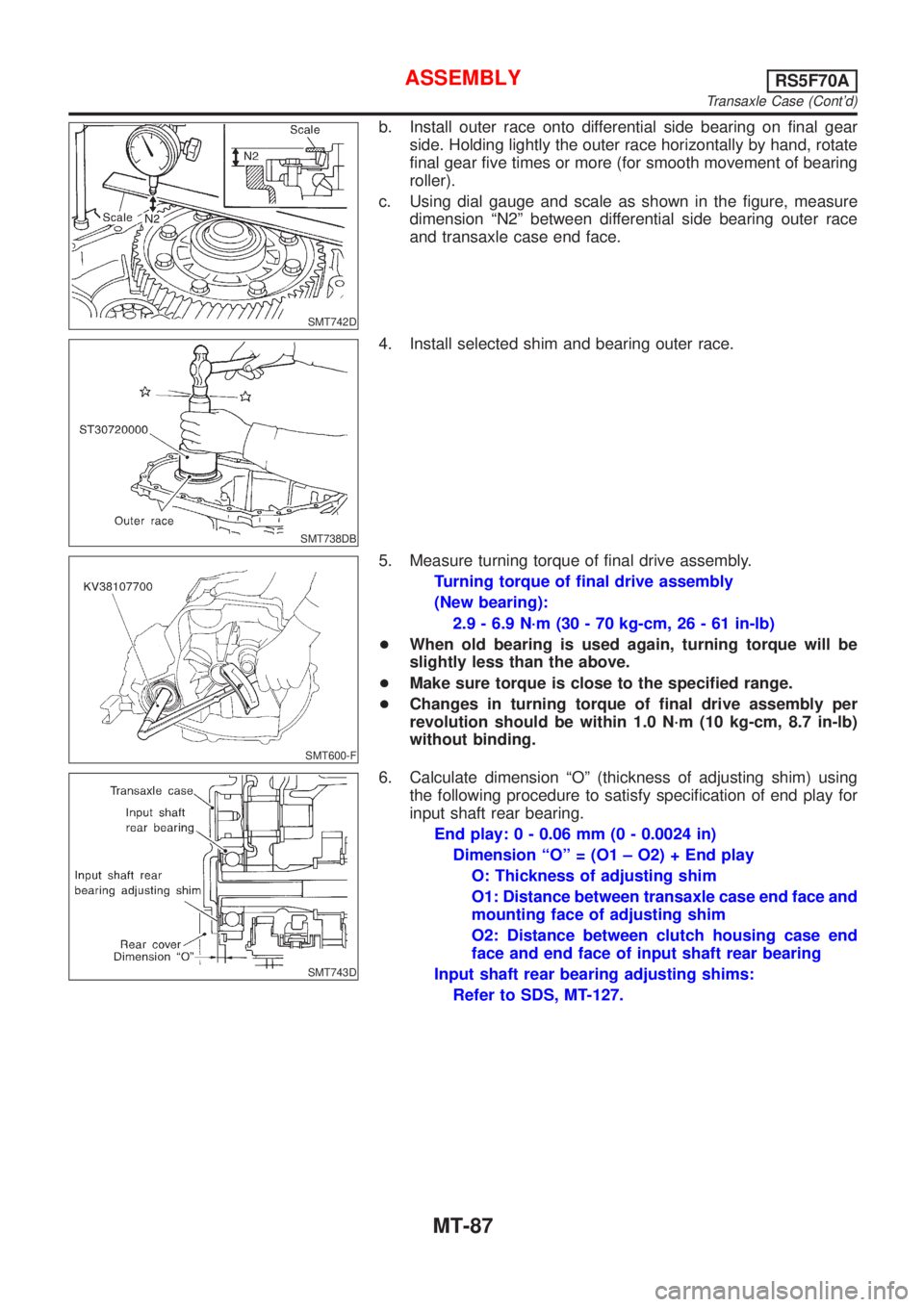
b. Install outer race onto differential side bearing on final gear
side. Holding lightly the outer race horizontally by hand, rotate
final gear five times or more (for smooth movement of bearing
roller).
c. Using dial gauge and scale as shown in the figure, measure
dimension ªN2º between differential side bearing outer race
and transaxle case end face.
SMT738DB
4. Install selected shim and bearing outer race.
SMT600-F
5. Measure turning torque of final drive assembly.
Turning torque of final drive assembly
(New bearing):
2.9 - 6.9 N´m (30 - 70 kg-cm, 26 - 61 in-lb)
+When old bearing is used again, turning torque will be
slightly less than the above.
+Make sure torque is close to the specified range.
+Changes in turning torque of final drive assembly per
revolution should be within 1.0 N´m (10 kg-cm, 8.7 in-lb)
without binding.
SMT743D
6. Calculate dimension ªOº (thickness of adjusting shim) using
the following procedure to satisfy specification of end play for
input shaft rear bearing.
End play: 0 - 0.06 mm (0 - 0.0024 in)
Dimension ªOº = (O1 ± O2) + End play
O: Thickness of adjusting shim
O1: Distance between transaxle case end face and
mounting face of adjusting shim
O2: Distance between clutch housing case end
face and end face of input shaft rear bearing
Input shaft rear bearing adjusting shims:
Refer to SDS, MT-127.
ASSEMBLYRS5F70A
Transaxle Case (Cont'd)
MT-87
Page 2689 of 2898
SMT070A
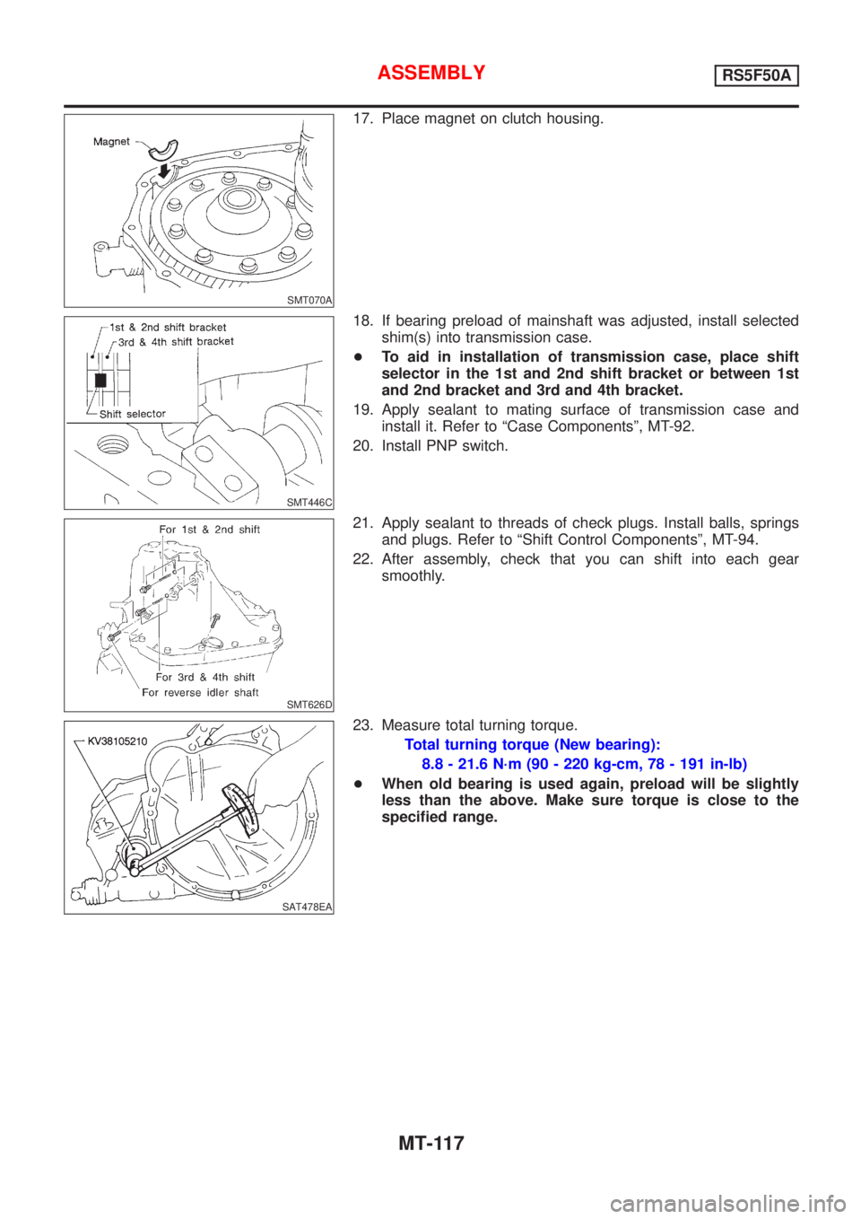
17. Place magnet on clutch housing.
SMT446C
18. If bearing preload of mainshaft was adjusted, install selected
shim(s) into transmission case.
+To aid in installation of transmission case, place shift
selector in the 1st and 2nd shift bracket or between 1st
and 2nd bracket and 3rd and 4th bracket.
19. Apply sealant to mating surface of transmission case and
install it. Refer to ªCase Componentsº, MT-92.
20. Install PNP switch.
SMT626D
21. Apply sealant to threads of check plugs. Install balls, springs
and plugs. Refer to ªShift Control Componentsº, MT-94.
22. After assembly, check that you can shift into each gear
smoothly.
SAT478EA
23. Measure total turning torque.
Total turning torque (New bearing):
8.8 - 21.6 N´m (90 - 220 kg-cm, 78 - 191 in-lb)
+When old bearing is used again, preload will be slightly
less than the above. Make sure torque is close to the
specified range.
ASSEMBLYRS5F50A
MT-117
Page 2748 of 2898
Disposal of Air Bag Module and Seat Belt Pre-
tensioner
NJRS0022+Before disposing of air bag module and seat belt pre-tensioner,
or vehicles equipped with such systems, deploy the systems.
If such systems have already been deployed due to an
accident, dispose of them as indicated in ªDISPOSING OF AIR
BAG MODULE AND SEAT BELT PRE-TENSIONERº (RS-46).
+When deploying the air bag module and seat belt pre-
tensioner, always use the Special Service Tool; Deployment
tool KV99106400.
+When deploying the air bag module and seat belt pre-
tensioner, stand at least 5 m (16 ft) away from the deployment
component.
+When deploying air bag module and seat belt pre-tensioner, a
fairly loud noise is made, followed by smoke being released.
The smoke is not poisonous, however, be careful not to inhale
smoke since it irritates the throat and can cause choking.
+Always activate one air bag module at a time.
+Due to heat, leave air bag module unattended for more than
30 minutes after deployment. Also leave seat belt pre-ten-
sioner unattended for move than 10 minutes after deployment.
+Be sure to wear gloves when handling a deployed air bag
module and seat belt pre-tensioner.
+Never apply water to the deployed air bag module and seat
belt pre-tensioner.
+Wash your hands clean after finishing work.
+Place the vehicle outdoors with an open space of at least 6 m
(20 ft) on all sides when deploying air bag module and seat belt
pre-tensioner while mounted in vehicle.
+Use a voltmeter to make sure the vehicle battery is fully
charged.
+Do not dispose of the air bag module and seat belt pre-ten-
sioner un-deployed.
SRS005-B
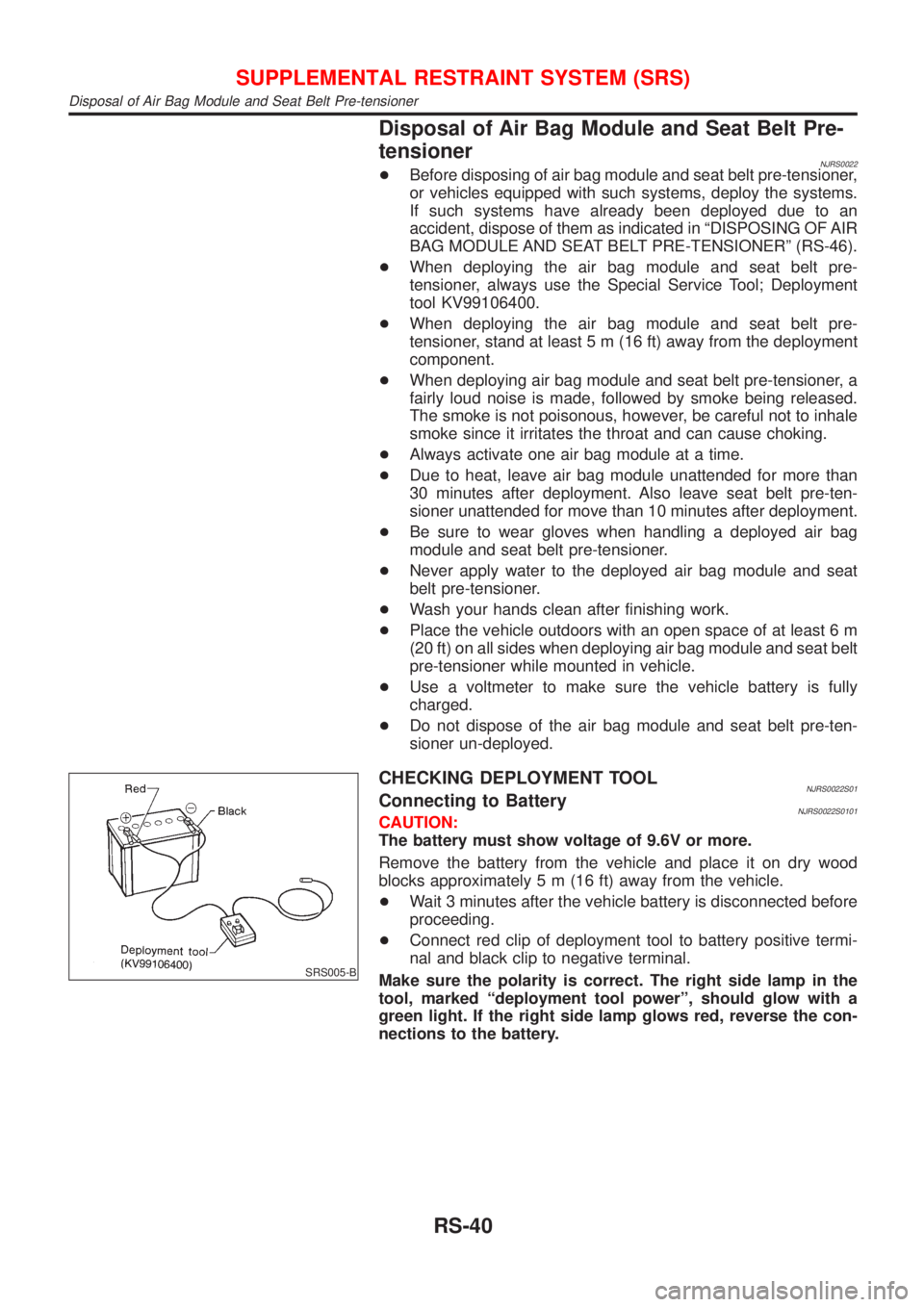
CHECKING DEPLOYMENT TOOLNJRS0022S01Connecting to BatteryNJRS0022S0101CAUTION:
The battery must show voltage of 9.6V or more.
Remove the battery from the vehicle and place it on dry wood
blocks approximately 5 m (16 ft) away from the vehicle.
+Wait 3 minutes after the vehicle battery is disconnected before
proceeding.
+Connect red clip of deployment tool to battery positive termi-
nal and black clip to negative terminal.
Make sure the polarity is correct. The right side lamp in the
tool, marked ªdeployment tool powerº, should glow with a
green light. If the right side lamp glows red, reverse the con-
nections to the battery.
SUPPLEMENTAL RESTRAINT SYSTEM (SRS)
Disposal of Air Bag Module and Seat Belt Pre-tensioner
RS-40
Page 2757 of 2898
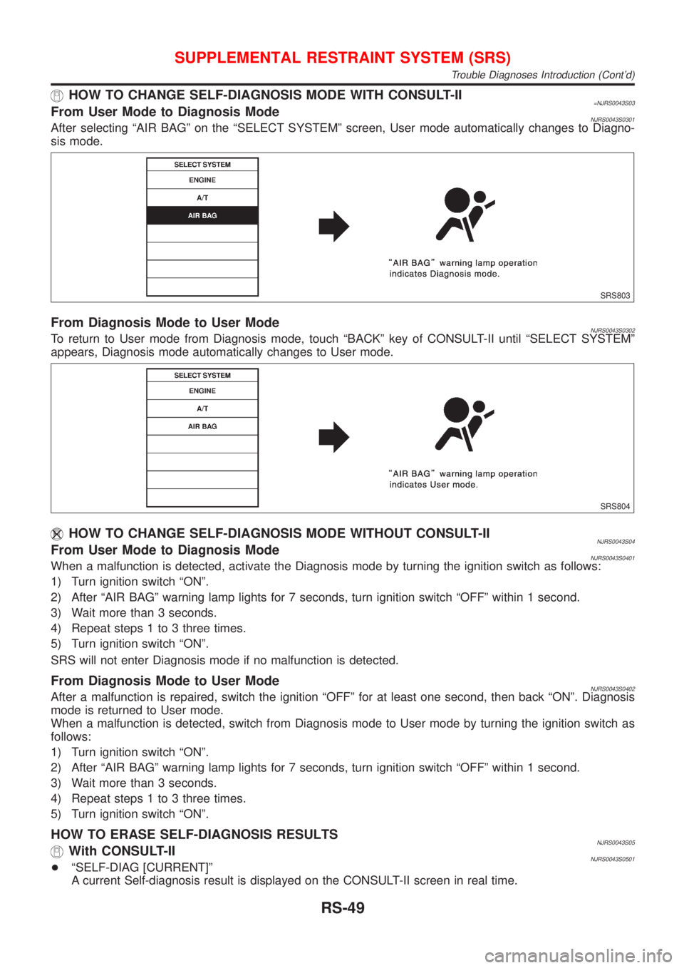
HOW TO CHANGE SELF-DIAGNOSIS MODE WITH CONSULT-II=NJRS0043S03From User Mode to Diagnosis ModeNJRS0043S0301After selecting ªAIR BAGº on the ªSELECT SYSTEMº screen, User mode automatically changes to Diagno-
sis mode.
SRS803
From Diagnosis Mode to User ModeNJRS0043S0302To return to User mode from Diagnosis mode, touch ªBACKº key of CONSULT-II until ªSELECT SYSTEMº
appears, Diagnosis mode automatically changes to User mode.
SRS804
HOW TO CHANGE SELF-DIAGNOSIS MODE WITHOUT CONSULT-IINJRS0043S04From User Mode to Diagnosis ModeNJRS0043S0401When a malfunction is detected, activate the Diagnosis mode by turning the ignition switch as follows:
1) Turn ignition switch ªONº.
2) After ªAIR BAGº warning lamp lights for 7 seconds, turn ignition switch ªOFFº within 1 second.
3) Wait more than 3 seconds.
4) Repeat steps 1 to 3 three times.
5) Turn ignition switch ªONº.
SRS will not enter Diagnosis mode if no malfunction is detected.
From Diagnosis Mode to User ModeNJRS0043S0402After a malfunction is repaired, switch the ignition ªOFFº for at least one second, then back ªONº. Diagnosis
mode is returned to User mode.
When a malfunction is detected, switch from Diagnosis mode to User mode by turning the ignition switch as
follows:
1) Turn ignition switch ªONº.
2) After ªAIR BAGº warning lamp lights for 7 seconds, turn ignition switch ªOFFº within 1 second.
3) Wait more than 3 seconds.
4) Repeat steps 1 to 3 three times.
5) Turn ignition switch ªONº.
HOW TO ERASE SELF-DIAGNOSIS RESULTSNJRS0043S05With CONSULT-IINJRS0043S0501+ªSELF-DIAG [CURRENT]º
A current Self-diagnosis result is displayed on the CONSULT-II screen in real time.
SUPPLEMENTAL RESTRAINT SYSTEM (SRS)
Trouble Diagnoses Introduction (Cont'd)
RS-49
Page 2782 of 2898
SRS800
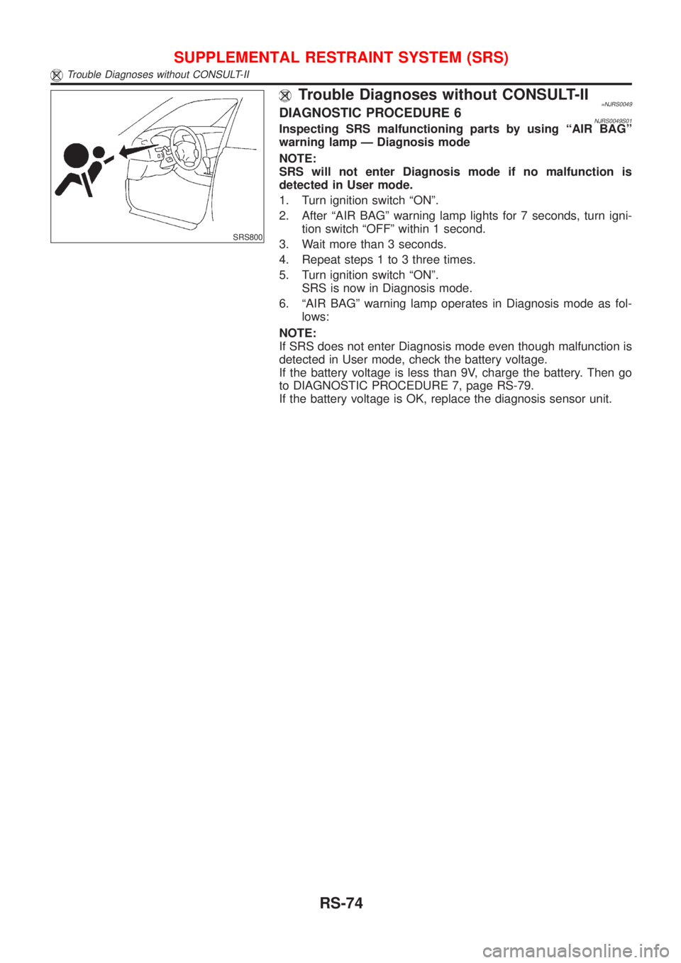
Trouble Diagnoses without CONSULT-II=NJRS0049DIAGNOSTIC PROCEDURE 6NJRS0049S01Inspecting SRS malfunctioning parts by using ªAIR BAGº
warning lamp Ð Diagnosis mode
NOTE:
SRS will not enter Diagnosis mode if no malfunction is
detected in User mode.
1. Turn ignition switch ªONº.
2. After ªAIR BAGº warning lamp lights for 7 seconds, turn igni-
tion switch ªOFFº within 1 second.
3. Wait more than 3 seconds.
4. Repeat steps 1 to 3 three times.
5. Turn ignition switch ªONº.
SRS is now in Diagnosis mode.
6. ªAIR BAGº warning lamp operates in Diagnosis mode as fol-
lows:
NOTE:
If SRS does not enter Diagnosis mode even though malfunction is
detected in User mode, check the battery voltage.
If the battery voltage is less than 9V, charge the battery. Then go
to DIAGNOSTIC PROCEDURE 7, page RS-79.
If the battery voltage is OK, replace the diagnosis sensor unit.
SUPPLEMENTAL RESTRAINT SYSTEM (SRS)
Trouble Diagnoses without CONSULT-II
RS-74
Page 2788 of 2898
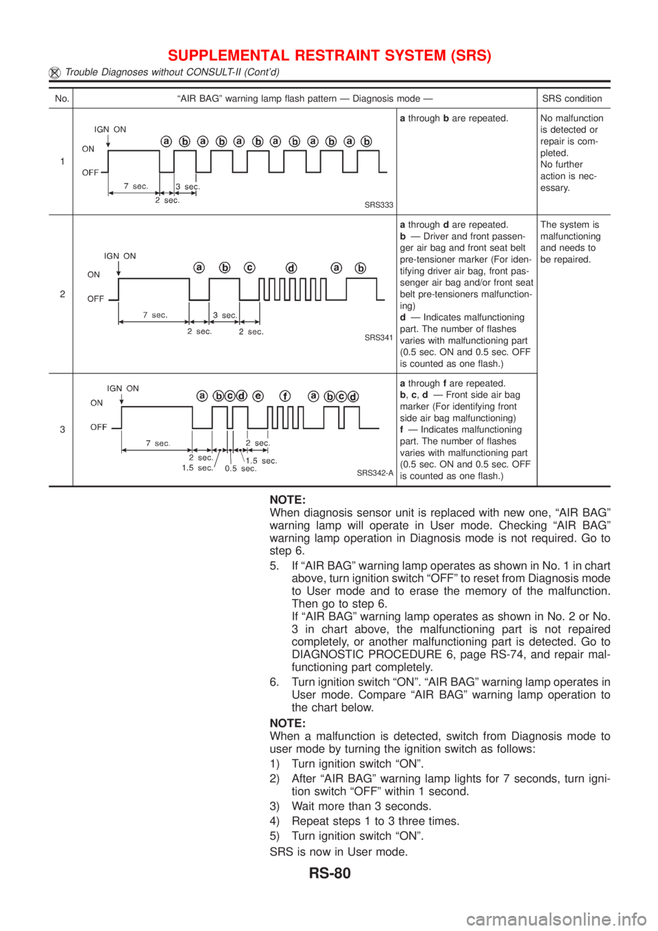
No. ªAIR BAGº warning lamp flash pattern Ð Diagnosis mode Ð SRS condition
1
SRS333
athroughbare repeated. No malfunction
is detected or
repair is com-
pleted.
No further
action is nec-
essary.
2
SRS341
athroughdare repeated.
bÐ Driver and front passen-
ger air bag and front seat belt
pre-tensioner marker (For iden-
tifying driver air bag, front pas-
senger air bag and/or front seat
belt pre-tensioners malfunction-
ing)
dÐ Indicates malfunctioning
part. The number of flashes
varies with malfunctioning part
(0.5 sec. ON and 0.5 sec. OFF
is counted as one flash.)The system is
malfunctioning
and needs to
be repaired.
3
SRS342-A
athroughfare repeated.
b,c,dÐ Front side air bag
marker (For identifying front
side air bag malfunctioning)
fÐ Indicates malfunctioning
part. The number of flashes
varies with malfunctioning part
(0.5 sec. ON and 0.5 sec. OFF
is counted as one flash.)
NOTE:
When diagnosis sensor unit is replaced with new one, ªAIR BAGº
warning lamp will operate in User mode. Checking ªAIR BAGº
warning lamp operation in Diagnosis mode is not required. Go to
step 6.
5. If ªAIR BAGº warning lamp operates as shown in No. 1 in chart
above, turn ignition switch ªOFFº to reset from Diagnosis mode
to User mode and to erase the memory of the malfunction.
Then go to step 6.
If ªAIR BAGº warning lamp operates as shown in No. 2 or No.
3 in chart above, the malfunctioning part is not repaired
completely, or another malfunctioning part is detected. Go to
DIAGNOSTIC PROCEDURE 6, page RS-74, and repair mal-
functioning part completely.
6. Turn ignition switch ªONº. ªAIR BAGº warning lamp operates in
User mode. Compare ªAIR BAGº warning lamp operation to
the chart below.
NOTE:
When a malfunction is detected, switch from Diagnosis mode to
user mode by turning the ignition switch as follows:
1) Turn ignition switch ªONº.
2) After ªAIR BAGº warning lamp lights for 7 seconds, turn igni-
tion switch ªOFFº within 1 second.
3) Wait more than 3 seconds.
4) Repeat steps 1 to 3 three times.
5) Turn ignition switch ªONº.
SRS is now in User mode.
SUPPLEMENTAL RESTRAINT SYSTEM (SRS)
Trouble Diagnoses without CONSULT-II (Cont'd)
RS-80