2001 NISSAN ALMERA light
[x] Cancel search: lightPage 2237 of 2898
JEM140G
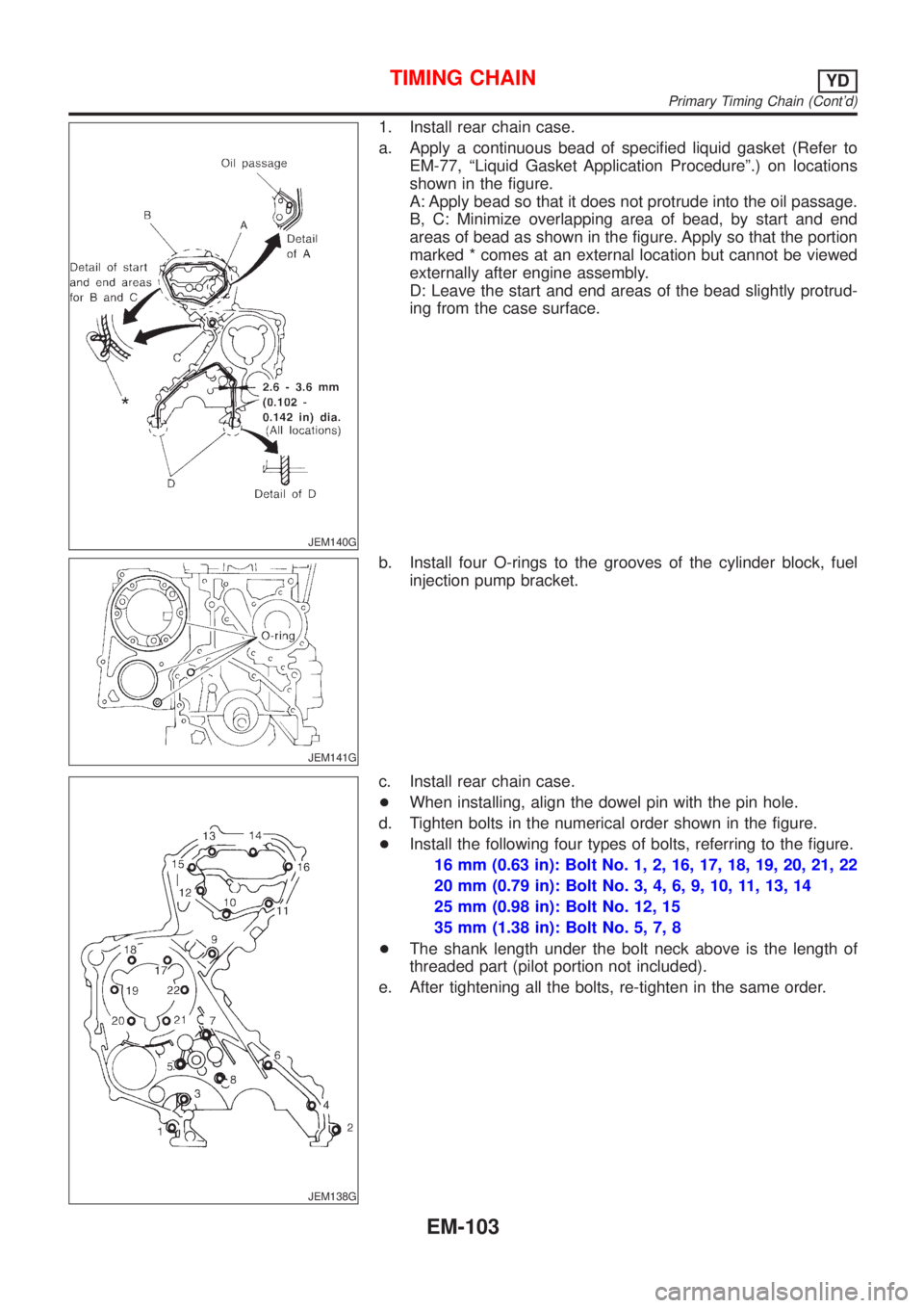
1. Install rear chain case.
a. Apply a continuous bead of specified liquid gasket (Refer to
EM-77, ªLiquid Gasket Application Procedureº.) on locations
shown in the figure.
A: Apply bead so that it does not protrude into the oil passage.
B, C: Minimize overlapping area of bead, by start and end
areas of bead as shown in the figure. Apply so that the portion
marked * comes at an external location but cannot be viewed
externally after engine assembly.
D: Leave the start and end areas of the bead slightly protrud-
ing from the case surface.
JEM141G
b. Install four O-rings to the grooves of the cylinder block, fuel
injection pump bracket.
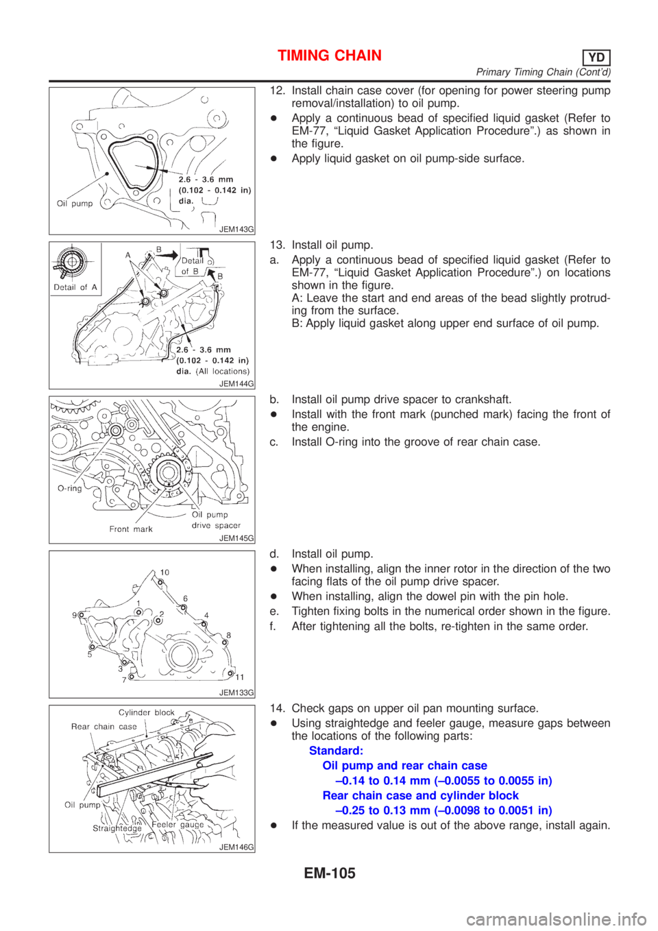
JEM138G
c. Install rear chain case.
+When installing, align the dowel pin with the pin hole.
d. Tighten bolts in the numerical order shown in the figure.
+Install the following four types of bolts, referring to the figure.
16 mm (0.63 in): Bolt No. 1, 2, 16, 17, 18, 19, 20, 21, 22
20 mm (0.79 in): Bolt No. 3, 4, 6, 9, 10, 11, 13, 14
25 mm (0.98 in): Bolt No. 12, 15
35 mm (1.38 in): Bolt No. 5, 7, 8
+The shank length under the bolt neck above is the length of
threaded part (pilot portion not included).
e. After tightening all the bolts, re-tighten in the same order.
TIMING CHAINYD
Primary Timing Chain (Cont'd)
EM-103
Page 2239 of 2898
JEM143G
12. Install chain case cover (for opening for power steering pump
removal/installation) to oil pump.
+Apply a continuous bead of specified liquid gasket (Refer to
EM-77, ªLiquid Gasket Application Procedureº.) as shown in
the figure.
+Apply liquid gasket on oil pump-side surface.
JEM144G
13. Install oil pump.
a. Apply a continuous bead of specified liquid gasket (Refer to
EM-77, ªLiquid Gasket Application Procedureº.) on locations
shown in the figure.
A: Leave the start and end areas of the bead slightly protrud-
ing from the surface.
B: Apply liquid gasket along upper end surface of oil pump.
JEM145G
b. Install oil pump drive spacer to crankshaft.
+Install with the front mark (punched mark) facing the front of
the engine.
c. Install O-ring into the groove of rear chain case.
JEM133G
d. Install oil pump.
+When installing, align the inner rotor in the direction of the two
facing flats of the oil pump drive spacer.
+When installing, align the dowel pin with the pin hole.
e. Tighten fixing bolts in the numerical order shown in the figure.
f. After tightening all the bolts, re-tighten in the same order.
JEM146G
14. Check gaps on upper oil pan mounting surface.
+Using straightedge and feeler gauge, measure gaps between
the locations of the following parts:
Standard:
Oil pump and rear chain case
±0.14 to 0.14 mm (±0.0055 to 0.0055 in)
Rear chain case and cylinder block
±0.25 to 0.13 mm (±0.0098 to 0.0051 in)
+If the measured value is out of the above range, install again.
TIMING CHAINYD
Primary Timing Chain (Cont'd)
EM-105
Page 2350 of 2898
combination meter. The indicator blinks when the ignition switch is
in ªOFFº or ªACCº position. Therefore, NATS warns outsiders that
the vehicle is equipped with the anti-theft system.
+When NATS detects trouble, the security indicator lamp lights
up while ignition switch is in ªONº position.
This lighting up indicates that the anti-theft is not functioning,
so prompt service is required.
+When servicing NATS (trouble diagnoses, system initialization
and additional registration of other NATS ignition key IDs),
CONSULT-II hardware and CONSULT-II NATS software is
necessary.
Regarding the procedures of NATS initialization and NATS
ignition key ID registration, refer to CONSULT-II operation
manual, NATS.
Therefore, CONSULT-II NATS software (program card and
operation manual) must be kept strictly confidential to main-
tain the integrity of the anti-theft function.
+When servicing NATS (trouble diagnoses, system initialization
and additional registration of other NATS ignition key IDs), it
may be necessary to re-register original key identification.
Therefore, be sure to receive all keys from vehicle owner. A
maximum of five key IDs can be registered into NATS.
+When failing to start the engine first time using the key of
NATS, start as follows.
a) Leave the ignition key in ªONº position for approximately 5
seconds.
b) Turn ignition key to ªOFFº or ªLOCKº position and wait approxi-
mately 5 seconds.
c) Repeat step 1 and 2 again.
d) Restart the engine while keeping the key separate from any
others on key-chain.
SGI285
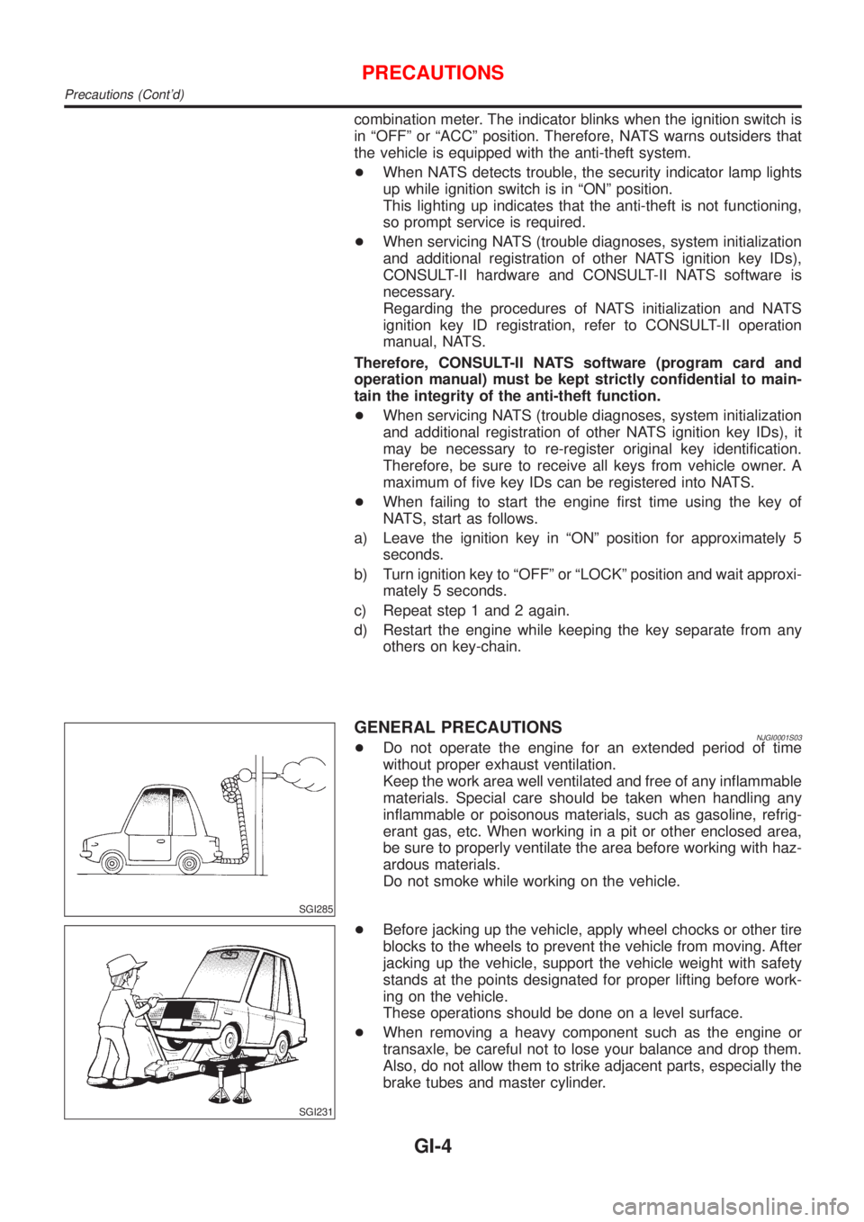
GENERAL PRECAUTIONSNJGI0001S03+Do not operate the engine for an extended period of time
without proper exhaust ventilation.
Keep the work area well ventilated and free of any inflammable
materials. Special care should be taken when handling any
inflammable or poisonous materials, such as gasoline, refrig-
erant gas, etc. When working in a pit or other enclosed area,
be sure to properly ventilate the area before working with haz-
ardous materials.
Do not smoke while working on the vehicle.
SGI231
+Before jacking up the vehicle, apply wheel chocks or other tire
blocks to the wheels to prevent the vehicle from moving. After
jacking up the vehicle, support the vehicle weight with safety
stands at the points designated for proper lifting before work-
ing on the vehicle.
These operations should be done on a level surface.
+When removing a heavy component such as the engine or
transaxle, be careful not to lose your balance and drop them.
Also, do not allow them to strike adjacent parts, especially the
brake tubes and master cylinder.
PRECAUTIONS
Precautions (Cont'd)
GI-4
Page 2359 of 2898
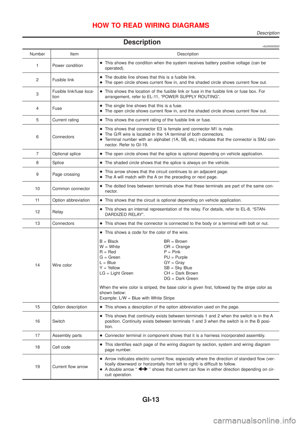
Description=NJGI0003S02
Number Item Description
1 Power condition+This shows the condition when the system receives battery positive voltage (can be
operated).
2 Fusible link+The double line shows that this is a fusible link.
+The open circle shows current flow in, and the shaded circle shows current flow out.
3Fusible link/fuse loca-
tion+This shows the location of the fusible link or fuse in the fusible link or fuse box. For
arrangement, refer to EL-11, ªPOWER SUPPLY ROUTINGº.
4 Fuse+The single line shows that this is a fuse.
+The open circle shows current flow in, and the shaded circle shows current flow out.
5 Current rating+This shows the current rating of the fusible link or fuse.
6 Connectors+This shows that connector E3 is female and connector M1 is male.
+The G/R wire is located in the 1A terminal of both connectors.
+Terminal number with an alphabet (1A, 5B, etc.) indicates that the connector is SMJ con-
nector. Refer to GI-19.
7 Optional splice+The open circle shows that the splice is optional depending on vehicle application.
8 Splice+The shaded circle shows that the splice is always on the vehicle.
9 Page crossing+This arrow shows that the circuit continues to an adjacent page.
+The A will match with the A on the preceding or next page.
10 Common connector+The dotted lines between terminals show that these terminals are part of the same con-
nector.
11 Option abbreviation+This shows that the circuit is optional depending on vehicle application.
12 Relay+This shows an internal representation of the relay. For details, refer to EL-8, ªSTAN-
DARDIZED RELAYº.
13 Connectors+This shows that the connector is connected to the body or a terminal with bolt or nut.
14 Wire color+This shows a code for the color of the wire.
B = Black
W = White
R = Red
G = Green
L = Blue
Y = Yellow
LG = Light GreenBR = Brown
OR = Orange
P = Pink
PU = Purple
GY = Gray
SB = Sky Blue
CH = Dark Brown
DG = Dark Green
When the wire color is striped, the base color is given first, followed by the stripe color as
shown below:
Example: L/W = Blue with White Stripe
15 Option description+This shows a description of the option abbreviation used on the page.
16 Switch+This shows that continuity exists between terminals 1 and 2 when the switch is in the A
position. Continuity exists between terminals 1 and 3 when the switch is in the B posi-
tion.
17 Assembly parts+Connector terminal in component shows that it is a harness incorporated assembly.
18 Cell code+This identifies each page of the wiring diagram by section, system and wiring diagram
page number.
19 Current flow arrow+Arrow indicates electric current flow, especially where the direction of standard flow (ver-
tically downward or horizontally from left to right) is difficult to follow.
+A double arrow ª
º shows that current can flow in either direction depending on cir-
cuit operation.
HOW TO READ WIRING DIAGRAMS
Description
GI-13
Page 2368 of 2898
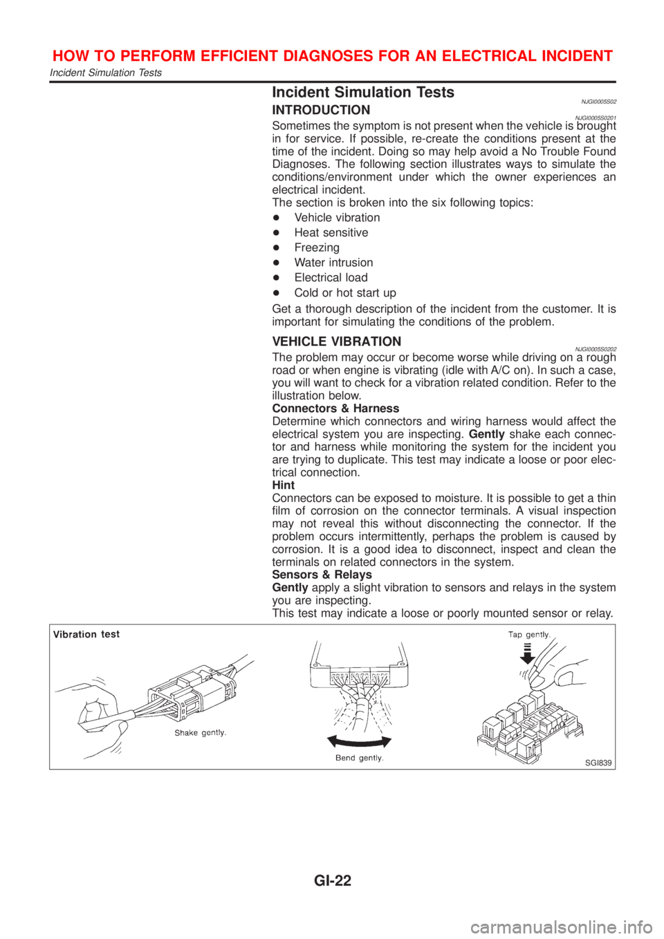
Incident Simulation TestsNJGI0005S02INTRODUCTIONNJGI0005S0201Sometimes the symptom is not present when the vehicle is brought
in for service. If possible, re-create the conditions present at the
time of the incident. Doing so may help avoid a No Trouble Found
Diagnoses. The following section illustrates ways to simulate the
conditions/environment under which the owner experiences an
electrical incident.
The section is broken into the six following topics:
+Vehicle vibration
+Heat sensitive
+Freezing
+Water intrusion
+Electrical load
+Cold or hot start up
Get a thorough description of the incident from the customer. It is
important for simulating the conditions of the problem.
VEHICLE VIBRATIONNJGI0005S0202The problem may occur or become worse while driving on a rough
road or when engine is vibrating (idle with A/C on). In such a case,
you will want to check for a vibration related condition. Refer to the
illustration below.
Connectors & Harness
Determine which connectors and wiring harness would affect the
electrical system you are inspecting.Gentlyshake each connec-
tor and harness while monitoring the system for the incident you
are trying to duplicate. This test may indicate a loose or poor elec-
trical connection.
Hint
Connectors can be exposed to moisture. It is possible to get a thin
film of corrosion on the connector terminals. A visual inspection
may not reveal this without disconnecting the connector. If the
problem occurs intermittently, perhaps the problem is caused by
corrosion. It is a good idea to disconnect, inspect and clean the
terminals on related connectors in the system.
Sensors & Relays
Gentlyapply a slight vibration to sensors and relays in the system
you are inspecting.
This test may indicate a loose or poorly mounted sensor or relay.
SGI839
HOW TO PERFORM EFFICIENT DIAGNOSES FOR AN ELECTRICAL INCIDENT
Incident Simulation Tests
GI-22
Page 2374 of 2898
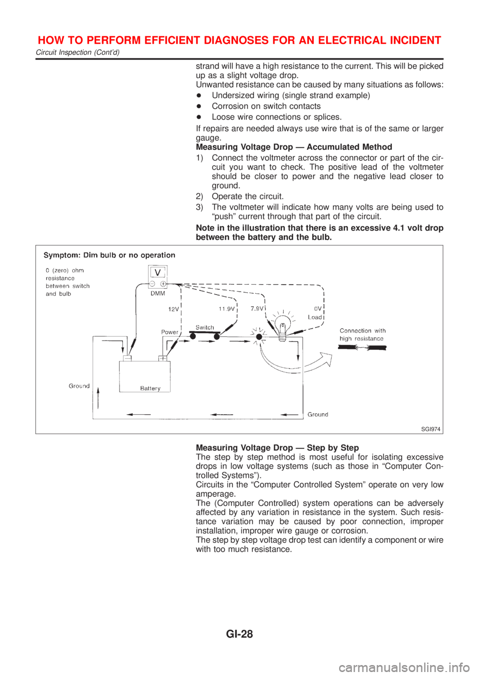
strand will have a high resistance to the current. This will be picked
up as a slight voltage drop.
Unwanted resistance can be caused by many situations as follows:
+Undersized wiring (single strand example)
+Corrosion on switch contacts
+Loose wire connections or splices.
If repairs are needed always use wire that is of the same or larger
gauge.
Measuring Voltage Drop Ð Accumulated Method
1) Connect the voltmeter across the connector or part of the cir-
cuit you want to check. The positive lead of the voltmeter
should be closer to power and the negative lead closer to
ground.
2) Operate the circuit.
3) The voltmeter will indicate how many volts are being used to
ªpushº current through that part of the circuit.
Note in the illustration that there is an excessive 4.1 volt drop
between the battery and the bulb.
SGI974
Measuring Voltage Drop Ð Step by Step
The step by step method is most useful for isolating excessive
drops in low voltage systems (such as those in ªComputer Con-
trolled Systemsº).
Circuits in the ªComputer Controlled Systemº operate on very low
amperage.
The (Computer Controlled) system operations can be adversely
affected by any variation in resistance in the system. Such resis-
tance variation may be caused by poor connection, improper
installation, improper wire gauge or corrosion.
The step by step voltage drop test can identify a component or wire
with too much resistance.
HOW TO PERFORM EFFICIENT DIAGNOSES FOR AN ELECTRICAL INCIDENT
Circuit Inspection (Cont'd)
GI-28
Page 2375 of 2898
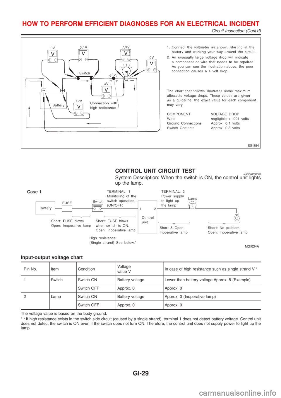
SGI854
CONTROL UNIT CIRCUIT TESTNJGI0005S0306System Description: When the switch is ON, the control unit lights
up the lamp.
MGI034A
Input-output voltage chart
Pin No. Item ConditionVoltage
value VIn case of high resistance such as single strand V *
1 Switch Switch ON Battery voltage Lower than battery voltage Approx. 8 (Example)
Switch OFF Approx. 0 Approx. 0
2 Lamp Switch ON Battery voltage Approx. 0 (Inoperative lamp)
Switch OFF Approx. 0 Approx. 0
The voltage value is based on the body ground.
* : If high resistance exists in the switch side circuit (caused by a single strand), terminal 1 does not detect battery voltage. Control unit
does not detect the switch is ON even if the switch does not turn ON. Therefore, the control unit does not supply power to light up the
lamp.
HOW TO PERFORM EFFICIENT DIAGNOSES FOR AN ELECTRICAL INCIDENT
Circuit Inspection (Cont'd)
GI-29
Page 2376 of 2898
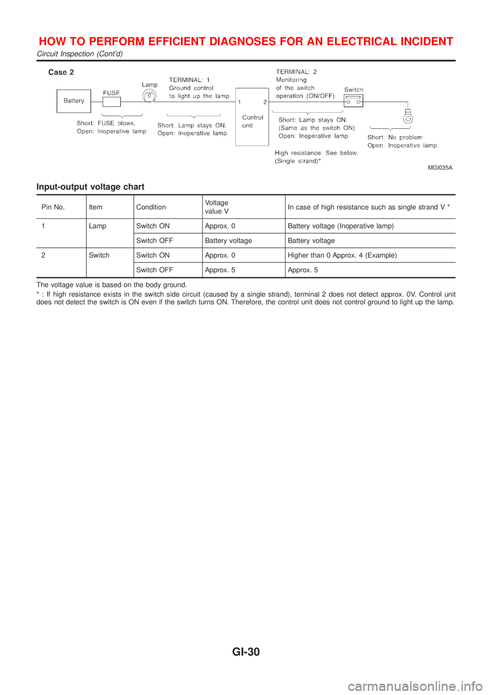
MGI035A
Input-output voltage chart
Pin No. Item ConditionVoltage
value VIn case of high resistance such as single strand V *
1 Lamp Switch ON Approx. 0 Battery voltage (Inoperative lamp)
Switch OFF Battery voltage Battery voltage
2 Switch Switch ON Approx. 0 Higher than 0 Approx. 4 (Example)
Switch OFF Approx. 5 Approx. 5
The voltage value is based on the body ground.
* : If high resistance exists in the switch side circuit (caused by a single strand), terminal 2 does not detect approx. 0V. Control unit
does not detect the switch is ON even if the switch turns ON. Therefore, the control unit does not control ground to light up the lamp.
HOW TO PERFORM EFFICIENT DIAGNOSES FOR AN ELECTRICAL INCIDENT
Circuit Inspection (Cont'd)
GI-30