Page 1764 of 2898

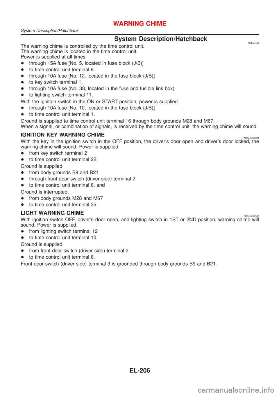
System Description/HatchbackNJEL0453The warning chime is controlled by the time control unit.
The warning chime is located in the time control unit.
Power is supplied at all times
+through 15A fuse [No. 5, located in fuse block (J/B)]
+to time control unit terminal 9.
+through 10A fuse [No. 12, located in the fuse block (J/B)]
+to key switch terminal 1.
+through 10A fuse (No. 38, located in the fuse and fusible link box)
+to lighting switch terminal 11.
With the ignition switch in the ON or START position, power is supplied
+through 10A fuse [No. 10, located in the fuse block (J/B)]
+to time control unit terminal 1.
Ground is supplied to time control unit terminal 16 through body grounds M28 and M67.
When a signal, or combination of signals, is received by the time control unit, the warning chime will sound.
IGNITION KEY WARNING CHIMENJEL0453S01With the key in the ignition switch in the OFF position, the driver's door open and driver's door locked, the
warning chime will sound. Power is supplied
+from key switch terminal 2
+to time control unit terminal 22.
Ground is supplied
+from body grounds B9 and B21
+through front door switch (driver side) terminal 2
+to time control unit terminal 6, and
Ground is interrupted,
+from body grounds M28 and M67
+to time control unit terminal 35
LIGHT WARNING CHIMENJEL0453S02With ignition switch OFF, driver's door open, and lighting switch in 1ST or 2ND position, warning chime will
sound. Power is supplied.
+from lighting switch terminal 12
+to time control unit terminal 10
Ground is supplied
+from front door switch (driver side) terminal 2
+to time control unit terminal 6.
Front door switch (driver side) terminal 3 is grounded through body grounds B9 and B21.
WARNING CHIME
System Description/Hatchback
EL-206
Page 1767 of 2898
Trouble Diagnoses/HatchbackNJEL0455SYMPTOM CHARTNJEL0455S01
REFERENCE PAGE (EL- ) 209 210 211 212 213
SYMPTOM
POWER SUPPLY AND
GROUND CIRCUIT CHECK
DIAGNOSTIC PROCEDURE 1
(LIGHTING SWITCH INPUT
SIGNAL CHECK)
DIAGNOSTIC PROCEDURE 2
(KEY SWITCH INSERT
SIGNAL CHECK)
DIAGNOSTIC PROCEDURE 3
(DOOR UNLOCK SENSOR CHECK)
DIAGNOSTIC PROCEDURE 4
Light warning chime does not acti-
vate.XX X
Ignition key warning chime does not
activate.XXXX
All warning chimes do not activate. XX
POWER SUPPLY AND GROUND CIRCUIT CHECKNJEL0455S02Power Supply Circuit CheckNJEL0455S0201
SEL447X
Ground Circuit CheckNJEL0455S0202
SEL448X
WARNING CHIME
Trouble Diagnoses/Hatchback
EL-209
Page 1768 of 2898
DIAGNOSTIC PROCEDURE 1 (LIGHTING SWITCH
INPUT SIGNAL CHECK)
=NJEL0455S03
1 CHECK LIGHTING SWITCH INPUT SIGNAL
Check voltage between time control unit terminal 10 and ground.
SEL449X
OK or NG
OK©Lighting switch is OK.
NG©Check the following.
+10A fuse (No. 38, located in the fuse and fusible link box)
+Harness for open or short between time control unit and lighting switch/daytime light
control unit
+Lighting switch
WARNING CHIME
Trouble Diagnoses/Hatchback (Cont'd)
EL-210
Page 1794 of 2898
Wiring Diagram Ð CIGAR Ð/SedanNJEL0156
HEL900A
CIGARETTE LIGHTER
Wiring Diagram Ð CIGAR Ð/Sedan
EL-236
Page 1795 of 2898
Wiring Diagram Ð CIGAR Ð/HatchbackNJEL0461
MEL188M
CIGARETTE LIGHTER
Wiring Diagram Ð CIGAR Ð/Hatchback
EL-237
Page 1815 of 2898

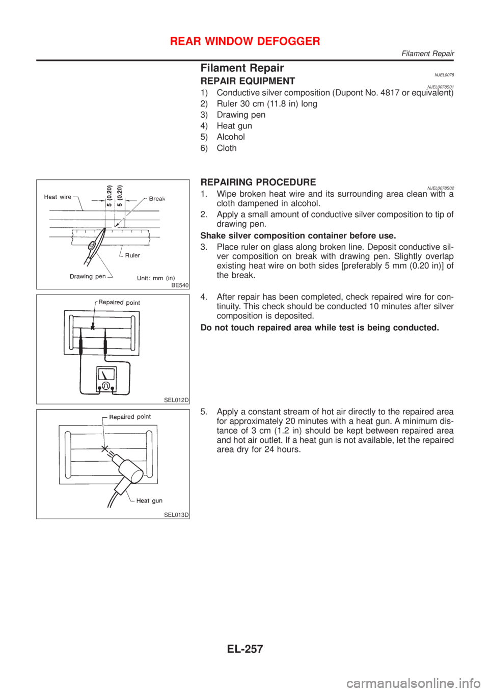
Filament RepairNJEL0078REPAIR EQUIPMENTNJEL0078S011) Conductive silver composition (Dupont No. 4817 or equivalent)
2) Ruler 30 cm (11.8 in) long
3) Drawing pen
4) Heat gun
5) Alcohol
6) Cloth
BE540
REPAIRING PROCEDURENJEL0078S021. Wipe broken heat wire and its surrounding area clean with a
cloth dampened in alcohol.
2. Apply a small amount of conductive silver composition to tip of
drawing pen.
Shake silver composition container before use.
3. Place ruler on glass along broken line. Deposit conductive sil-
ver composition on break with drawing pen. Slightly overlap
existing heat wire on both sides [preferably 5 mm (0.20 in)] of
the break.
SEL012D
4. After repair has been completed, check repaired wire for con-
tinuity. This check should be conducted 10 minutes after silver
composition is deposited.
Do not touch repaired area while test is being conducted.
SEL013D
5. Apply a constant stream of hot air directly to the repaired area
for approximately 20 minutes with a heat gun. A minimum dis-
tance of 3 cm (1.2 in) should be kept between repaired area
and hot air outlet. If a heat gun is not available, let the repaired
area dry for 24 hours.
REAR WINDOW DEFOGGER
Filament Repair
EL-257
Page 1972 of 2898
Description/Sedan=NJEL0403OUTLINENJEL0403S01The time control unit totally controls the following body electrical system operations.
+Warning chime
+Rear defogger
+Power door lock
+Interior lamp
INPUT/OUTPUTNJEL0403S02
System Input Output
Power door lockDoor lock and unlock switch
Door switches
Door unlock sensor
Door key cylinder switchesDoor lock actuator
Warning chimeKey switch (Insert)
Ignition switch (ON)
Lighting switch (1st)
Door switch driver side
Door unlock sensorWarning chime (located in time control unit)
Rear window defoggerIgnition switch (ON)
Rear window defogger switchRear window defogger relay
Interior lampDoor switches
Front door unlock sensor
Ignition switch (ON)
Key switch (Insert)Interior lamp
TIME CONTROL UNIT
Description/Sedan
EL-414
Page 1974 of 2898

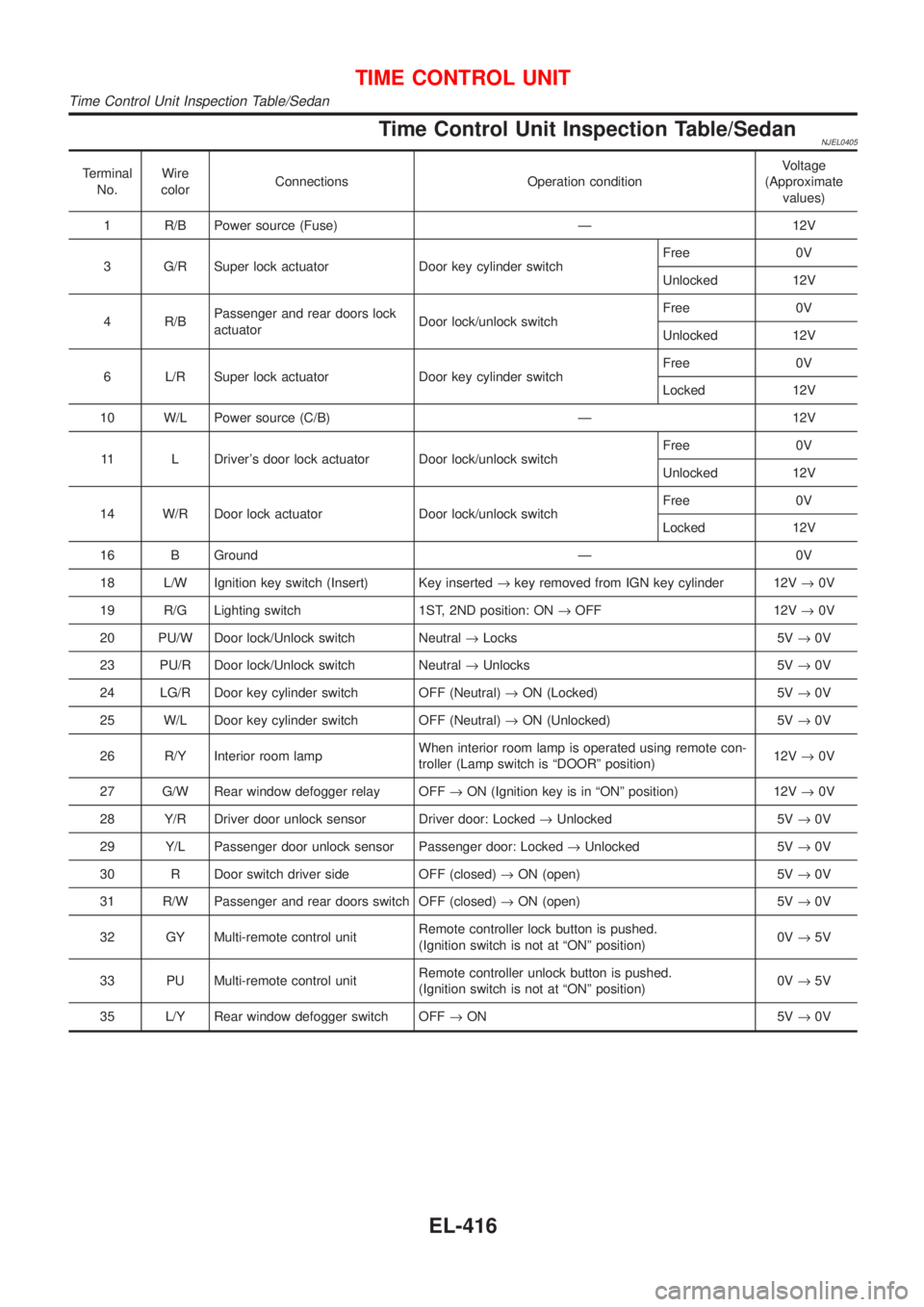
Time Control Unit Inspection Table/SedanNJEL0405
Terminal
No.Wire
colorConnections Operation conditionVoltage
(Approximate
values)
1 R/B Power source (Fuse) Ð 12V
3 G/R Super lock actuator Door key cylinder switchFree 0V
Unlocked 12V
4 R/BPassenger and rear doors lock
actuatorDoor lock/unlock switchFree 0V
Unlocked 12V
6 L/R Super lock actuator Door key cylinder switchFree 0V
Locked 12V
10 W/L Power source (C/B) Ð 12V
11 L Driver's door lock actuator Door lock/unlock switchFree 0V
Unlocked 12V
14 W/R Door lock actuator Door lock/unlock switchFree 0V
Locked 12V
16 B Ground Ð 0V
18 L/W Ignition key switch (Insert) Key inserted®key removed from IGN key cylinder 12V®0V
19 R/G Lighting switch 1ST, 2ND position: ON®OFF 12V®0V
20 PU/W Door lock/Unlock switch Neutral®Locks 5V®0V
23 PU/R Door lock/Unlock switch Neutral®Unlocks 5V®0V
24 LG/R Door key cylinder switch OFF (Neutral)®ON (Locked) 5V®0V
25 W/L Door key cylinder switch OFF (Neutral)®ON (Unlocked) 5V®0V
26 R/Y Interior room lampWhen interior room lamp is operated using remote con-
troller (Lamp switch is ªDOORº position)12V®0V
27 G/W Rear window defogger relay OFF®ON (Ignition key is in ªONº position) 12V®0V
28 Y/R Driver door unlock sensor Driver door: Locked®Unlocked 5V®0V
29 Y/L Passenger door unlock sensor Passenger door: Locked®Unlocked 5V®0V
30 R Door switch driver side OFF (closed)®ON (open) 5V®0V
31 R/W Passenger and rear doors switch OFF (closed)®ON (open) 5V®0V
32 GY Multi-remote control unitRemote controller lock button is pushed.
(Ignition switch is not at ªONº position)0V®5V
33 PU Multi-remote control unitRemote controller unlock button is pushed.
(Ignition switch is not at ªONº position)0V®5V
35 L/Y Rear window defogger switch OFF®ON 5V®0V
TIME CONTROL UNIT
Time Control Unit Inspection Table/Sedan
EL-416