2001 NISSAN ALMERA light
[x] Cancel search: lightPage 1351 of 2898
DTC and MI Detection LogicNJEC0626When a malfunction is detected, the malfunction (DTC) is stored in the ECM memory.
The MI will light up each time the ECM detects malfunction. For diagnostic items causing the MI to light up,
refer to ªTROUBLE DIAGNOSIS Ð INDEXº, EC-596.
Diagnostic Trouble Code (DTC)NJEC0627HOW TO READ DTCNJEC0627S01The DTC can be read by the following methods.
Without CONSULT-II
ECM displays the DTC by a set of four digit numbers with MI illumination in the diagnostic test mode II (Self-
diagnostic results). Example: 0103, 0807, 1002, etc.
With CONSULT-II
CONSULT-II displays the DTC in ªSELF-DIAG RESULTSº mode. Examples: P0115, P0571, P1202, etc.
These DTCs are prescribed by ISO15031-6.
(CONSULT-II also displays the malfunctioning component or system.)
+Output of the trouble code means that the indicated circuit has a malfunction. However, in the Mode
II it does not indicate whether the malfunction is still occurring or occurred in the past and returned
to normal.
CONSULT-II can identify them. Therefore, using CONSULT-II (if available) is recommended.
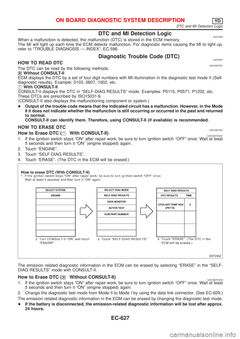
HOW TO ERASE DTCNJEC0627S02How to Erase DTC (With CONSULT-II)NJEC0627S02011. If the ignition switch stays ªONº after repair work, be sure to turn ignition switch ªOFFº once. Wait at least
5 seconds and then turn it ªONº (engine stopped) again.
2. Touch ªENGINEº.
3. Touch ªSELF-DIAG RESULTSº.
4. Touch ªERASEº. (The DTC in the ECM will be erased.)
SEF246Z
The emission related diagnostic information in the ECM can be erased by selecting ªERASEº in the ªSELF-
DIAG RESULTSº mode with CONSULT-II.
How to Erase DTC (Without CONSULT-II)NJEC0627S02021. If the ignition switch stays ªONº after repair work, be sure to turn ignition switch ªOFFº once. Wait at least
5 seconds and then turn it ªONº (engine stopped) again.
2. Change the diagnostic test mode from Mode II to Mode I by using the data link connector. (See EC-629.)
The emission related diagnostic information in the ECM can be erased by changing the diagnostic test mode.
+If the battery is disconnected, the emission-related diagnostic information will be lost after approx.
24 hours.
ON BOARD DIAGNOSTIC SYSTEM DESCRIPTIONYD
DTC and MI Detection Logic
EC-627
Page 1352 of 2898
+Erasing the emission-related diagnostic information using CONSULT-II is easier and quicker than
switching the diagnostic test mode using the data link connector.
Malfunction Indicator (MI)
DESCRIPTIONNJEC0628
SAT652J
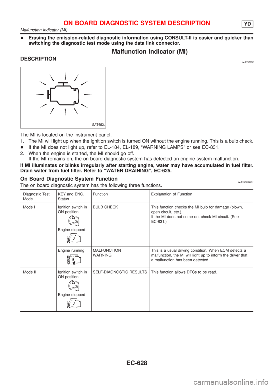
The MI is located on the instrument panel.
1. The MI will light up when the ignition switch is turned ON without the engine running. This is a bulb check.
+If the MI does not light up, refer to EL-184, EL-189, ªWARNING LAMPSº or see EC-831.
2. When the engine is started, the MI should go off.
If the MI remains on, the on board diagnostic system has detected an engine system malfunction.
If MI illuminates or blinks irregularly after starting engine, water may have accumulated in fuel filter.
Drain water from fuel filter. Refer to ªWATER DRAININGº, EC-625.
On Board Diagnostic System FunctionNJEC0628S01The on board diagnostic system has the following three functions.
Diagnostic Test
ModeKEY and ENG.
StatusFunction Explanation of Function
Mode I Ignition switch in
ON position
Engine stopped
BULB CHECK This function checks the MI bulb for damage (blown,
open circuit, etc.).
If the MI does not come on, check MI circuit. (See
EC-831.)
Engine running
MALFUNCTION
WARNINGThis is a usual driving condition. When ECM detects a
malfunction, the MI will light up to inform the driver that
a malfunction has been detected.
Mode II Ignition switch in
ON position
Engine stopped
SELF-DIAGNOSTIC RESULTS This function allows DTCs to be read.
ON BOARD DIAGNOSTIC SYSTEM DESCRIPTIONYD
Malfunction Indicator (MI)
EC-628
Page 1355 of 2898
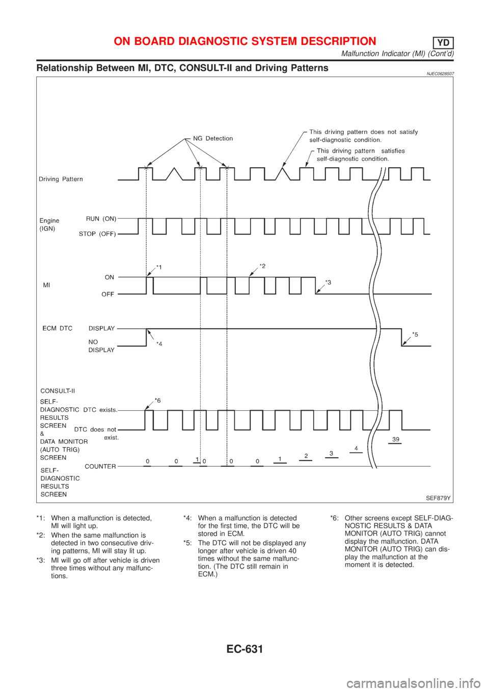
Relationship Between MI, DTC, CONSULT-II and Driving PatternsNJEC0628S07
SEF879Y
*1: When a malfunction is detected,
MI will light up.
*2: When the same malfunction is
detected in two consecutive driv-
ing patterns, MI will stay lit up.
*3: MI will go off after vehicle is driven
three times without any malfunc-
tions.*4: When a malfunction is detected
for the first time, the DTC will be
stored in ECM.
*5: The DTC will not be displayed any
longer after vehicle is driven 40
times without the same malfunc-
tion. (The DTC still remain in
ECM.)*6: Other screens except SELF-DIAG-
NOSTIC RESULTS & DATA
MONITOR (AUTO TRIG) cannot
display the malfunction. DATA
MONITOR (AUTO TRIG) can dis-
play the malfunction at the
moment it is detected.
ON BOARD DIAGNOSTIC SYSTEM DESCRIPTIONYD
Malfunction Indicator (MI) (Cont'd)
EC-631
Page 1365 of 2898
Basic InspectionNJEC0632Precaution:
Perform Basic Inspection without electrical or mechanical
loads applied;
+Headlamp switch is OFF,
+On vehicles equipped with daytime light systems, set
lighting switch to the 1st position to light only small
lamps.
+Air conditioner switch is OFF,
+Rear defogger switch is OFF,
+Steering wheel is in the straight-ahead position, etc.
1 INSPECTION START
1. Check service records for any recent repairs that may indicate a related problem.
2. Check the current need for scheduled maintenance, especially for fuel filter and air cleaner filter. Refer to MA-6, ªPeri-
odic Maintenanceº.
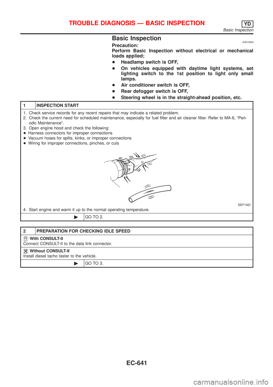
3. Open engine hood and check the following:
+Harness connectors for improper connections
+Vacuum hoses for splits, kinks, or improper connections
+Wiring for improper connections, pinches, or cuts
SEF142I
4. Start engine and warm it up to the normal operating temperature.
©GO TO 2.
2 PREPARATION FOR CHECKING IDLE SPEED
With CONSULT-II
Connect CONSULT-II to the data link connector.
Without CONSULT-II
Install diesel tacho tester to the vehicle.
©GO TO 3.
TROUBLE DIAGNOSIS Ð BASIC INSPECTIONYD
Basic Inspection
EC-641
Page 1380 of 2898
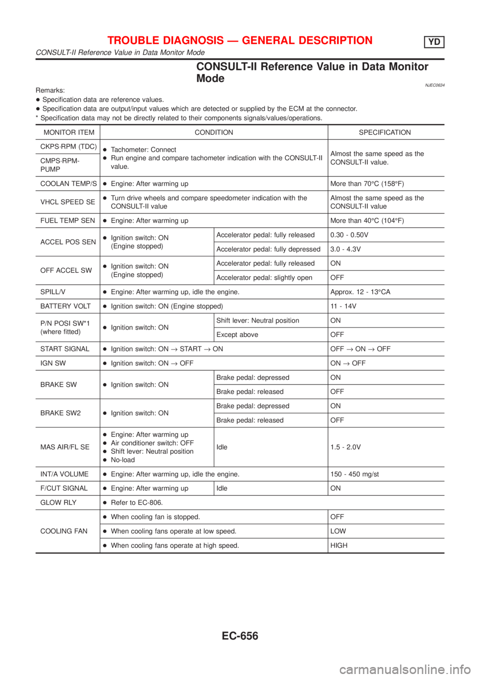
CONSULT-II Reference Value in Data Monitor
Mode
NJEC0634Remarks:
+Specification data are reference values.
+Specification data are output/input values which are detected or supplied by the ECM at the connector.
* Specification data may not be directly related to their components signals/values/operations.
MONITOR ITEM CONDITION SPECIFICATION
CKPS´RPM (TDC)
+Tachometer: Connect
+Run engine and compare tachometer indication with the CONSULT-II
value.Almost the same speed as the
CONSULT-II value. CMPS´RPM-
PUMP
COOLAN TEMP/S+Engine: After warming up More than 70ÉC (158ÉF)
VHCL SPEED SE+Turn drive wheels and compare speedometer indication with the
CONSULT-II valueAlmost the same speed as the
CONSULT-II value
FUEL TEMP SEN+Engine: After warming up More than 40ÉC (104ÉF)
ACCEL POS SEN+Ignition switch: ON
(Engine stopped)Accelerator pedal: fully released 0.30 - 0.50V
Accelerator pedal: fully depressed 3.0 - 4.3V
OFF ACCEL SW+Ignition switch: ON
(Engine stopped)Accelerator pedal: fully released ON
Accelerator pedal: slightly open OFF
SPILL/V+Engine: After warming up, idle the engine. Approx. 12 - 13ÉCA
BATTERY VOLT+Ignition switch: ON (Engine stopped) 11 - 14V
P/N POSI SW*1
(where fitted)+Ignition switch: ONShift lever: Neutral position ON
Except above OFF
START SIGNAL+Ignition switch: ON®START®ON OFF®ON®OFF
IGN SW+Ignition switch: ON®OFF ON®OFF
BRAKE SW+Ignition switch: ONBrake pedal: depressed ON
Brake pedal: released OFF
BRAKE SW2+Ignition switch: ONBrake pedal: depressed ON
Brake pedal: released OFF
MAS AIR/FL SE+Engine: After warming up
+Air conditioner switch: OFF
+Shift lever: Neutral position
+No-loadIdle 1.5 - 2.0V
INT/A VOLUME+Engine: After warming up, idle the engine. 150 - 450 mg/st
F/CUT SIGNAL+Engine: After warming up Idle ON
GLOW RLY+Refer to EC-806.
COOLING FAN+When cooling fan is stopped. OFF
+When cooling fans operate at low speed. LOW
+When cooling fans operate at high speed. HIGH
TROUBLE DIAGNOSIS Ð GENERAL DESCRIPTIONYD
CONSULT-II Reference Value in Data Monitor Mode
EC-656
Page 1409 of 2898
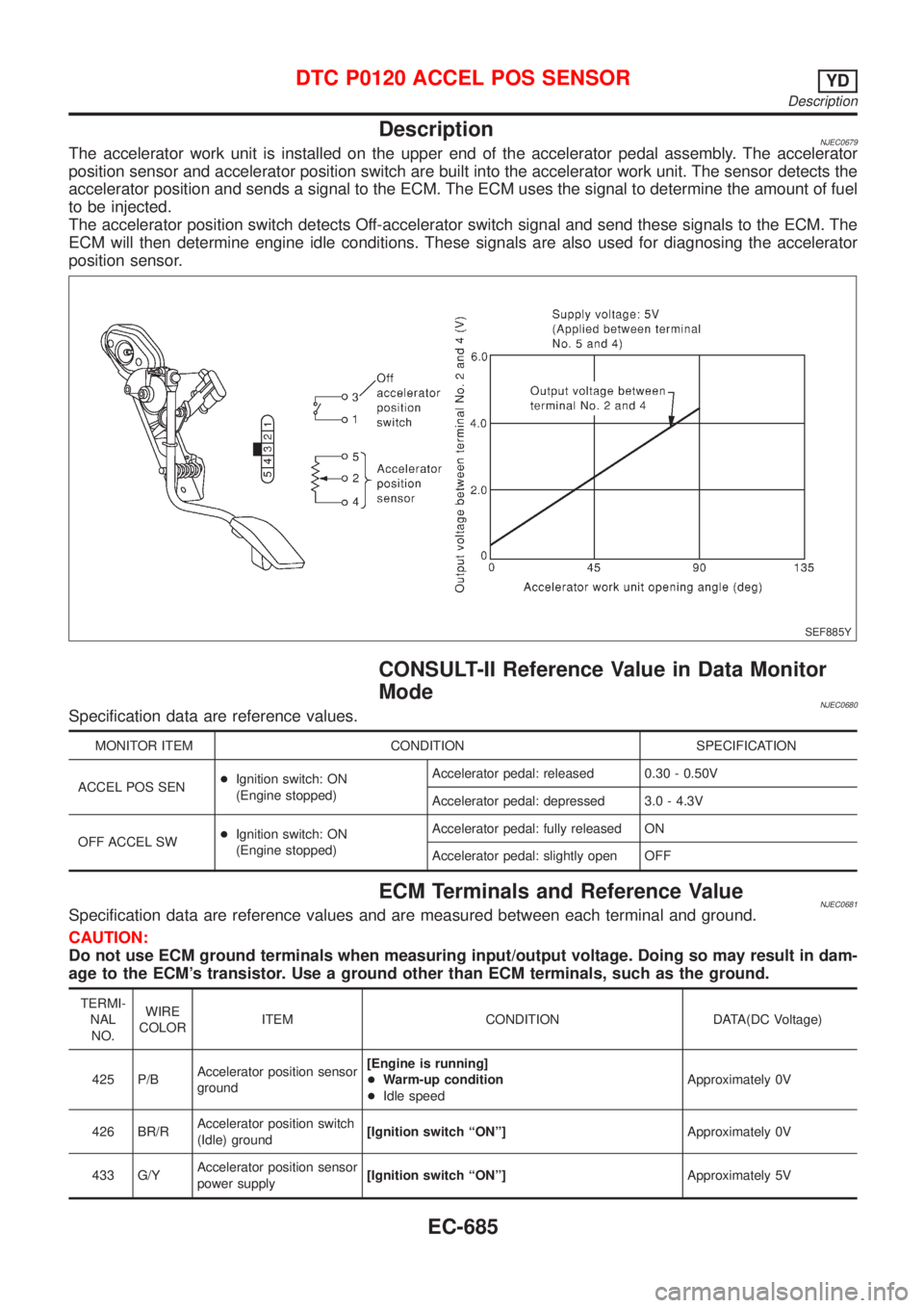
DescriptionNJEC0679The accelerator work unit is installed on the upper end of the accelerator pedal assembly. The accelerator
position sensor and accelerator position switch are built into the accelerator work unit. The sensor detects the
accelerator position and sends a signal to the ECM. The ECM uses the signal to determine the amount of fuel
to be injected.
The accelerator position switch detects Off-accelerator switch signal and send these signals to the ECM. The
ECM will then determine engine idle conditions. These signals are also used for diagnosing the accelerator
position sensor.
SEF885Y
CONSULT-II Reference Value in Data Monitor
Mode
NJEC0680Specification data are reference values.
MONITOR ITEM CONDITION SPECIFICATION
ACCEL POS SEN+Ignition switch: ON
(Engine stopped)Accelerator pedal: released 0.30 - 0.50V
Accelerator pedal: depressed 3.0 - 4.3V
OFF ACCEL SW+Ignition switch: ON
(Engine stopped)Accelerator pedal: fully released ON
Accelerator pedal: slightly open OFF
ECM Terminals and Reference ValueNJEC0681Specification data are reference values and are measured between each terminal and ground.
CAUTION:
Do not use ECM ground terminals when measuring input/output voltage. Doing so may result in dam-
age to the ECM's transistor. Use a ground other than ECM terminals, such as the ground.
TERMI-
NAL
NO.WIRE
COLORITEM CONDITION DATA(DC Voltage)
425 P/BAccelerator position sensor
ground[Engine is running]
+Warm-up condition
+Idle speedApproximately 0V
426 BR/RAccelerator position switch
(Idle) ground[Ignition switch ªONº]Approximately 0V
433 G/YAccelerator position sensor
power supply[Ignition switch ªONº]Approximately 5V
DTC P0120 ACCEL POS SENSORYD
Description
EC-685
Page 1559 of 2898
ELECTRICAL SYSTEM
SECTION
EL
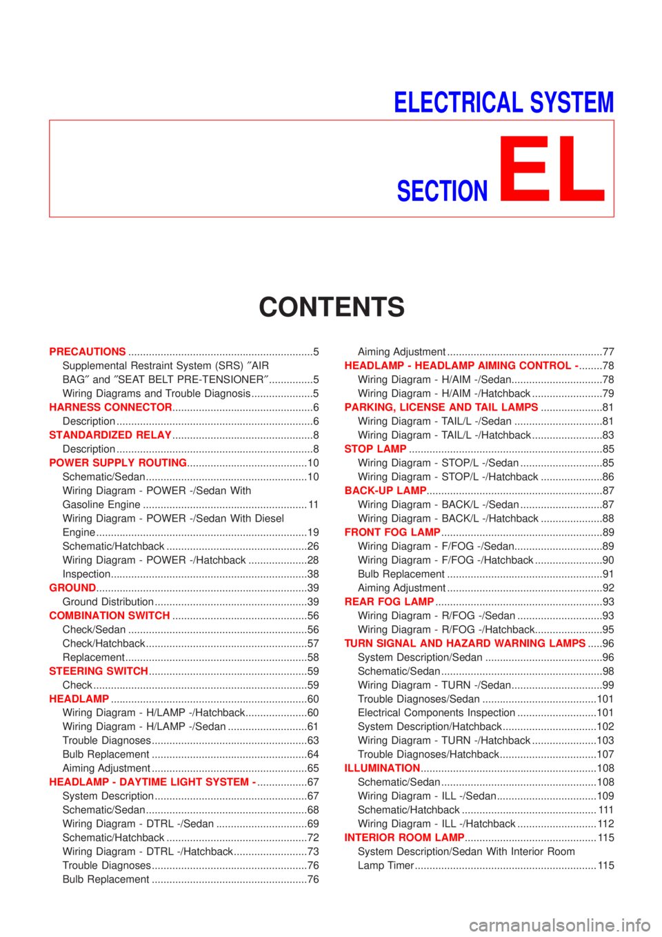
CONTENTS
PRECAUTIONS...............................................................5
Supplemental Restraint System (SRS)²AIR
BAG²and²SEAT BELT PRE-TENSIONER²...............5
Wiring Diagrams and Trouble Diagnosis .....................5
HARNESS CONNECTOR................................................6
Description ...................................................................6
STANDARDIZED RELAY................................................8
Description ...................................................................8
POWER SUPPLY ROUTING.........................................10
Schematic/Sedan .......................................................10
Wiring Diagram - POWER -/Sedan With
Gasoline Engine ........................................................ 11
Wiring Diagram - POWER -/Sedan With Diesel
Engine ........................................................................19
Schematic/Hatchback ................................................26
Wiring Diagram - POWER -/Hatchback ....................28
Inspection...................................................................38
GROUND........................................................................39
Ground Distribution ....................................................39
COMBINATION SWITCH..............................................56
Check/Sedan .............................................................56
Check/Hatchback .......................................................57
Replacement ..............................................................58
STEERING SWITCH......................................................59
Check .........................................................................59
HEADLAMP...................................................................60
Wiring Diagram - H/LAMP -/Hatchback.....................60
Wiring Diagram - H/LAMP -/Sedan ...........................61
Trouble Diagnoses.....................................................63
Bulb Replacement .....................................................64
Aiming Adjustment .....................................................65
HEADLAMP - DAYTIME LIGHT SYSTEM -.................67
System Description ....................................................67
Schematic/Sedan .......................................................68
Wiring Diagram - DTRL -/Sedan ...............................69
Schematic/Hatchback ................................................72
Wiring Diagram - DTRL -/Hatchback .........................73
Trouble Diagnoses.....................................................76
Bulb Replacement .....................................................76Aiming Adjustment .....................................................77
HEADLAMP - HEADLAMP AIMING CONTROL -........78
Wiring Diagram - H/AIM -/Sedan...............................78
Wiring Diagram - H/AIM -/Hatchback ........................79
PARKING, LICENSE AND TAIL LAMPS.....................81
Wiring Diagram - TAIL/L -/Sedan ..............................81
Wiring Diagram - TAIL/L -/Hatchback ........................83
STOP LAMP..................................................................85
Wiring Diagram - STOP/L -/Sedan ............................85
Wiring Diagram - STOP/L -/Hatchback .....................86
BACK-UP LAMP............................................................87
Wiring Diagram - BACK/L -/Sedan ............................87
Wiring Diagram - BACK/L -/Hatchback .....................88
FRONT FOG LAMP.......................................................89
Wiring Diagram - F/FOG -/Sedan..............................89
Wiring Diagram - F/FOG -/Hatchback .......................90
Bulb Replacement .....................................................91
Aiming Adjustment .....................................................92
REAR FOG LAMP.........................................................93
Wiring Diagram - R/FOG -/Sedan .............................93
Wiring Diagram - R/FOG -/Hatchback.......................95
TURN SIGNAL AND HAZARD WARNING LAMPS.....96
System Description/Sedan ........................................96
Schematic/Sedan .......................................................98
Wiring Diagram - TURN -/Sedan...............................99
Trouble Diagnoses/Sedan .......................................101
Electrical Components Inspection ...........................101
System Description/Hatchback ................................102
Wiring Diagram - TURN -/Hatchback ......................103
Trouble Diagnoses/Hatchback.................................107
ILLUMINATION............................................................108
Schematic/Sedan .....................................................108
Wiring Diagram - ILL -/Sedan ..................................109
Schematic/Hatchback .............................................. 111
Wiring Diagram - ILL -/Hatchback ........................... 112
INTERIOR ROOM LAMP............................................. 115
System Description/Sedan With Interior Room
Lamp Timer .............................................................. 115
Page 1560 of 2898
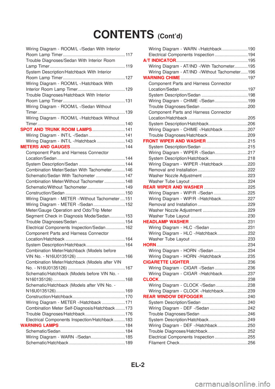
Wiring Diagram - ROOM/L -/Sedan With Interior
Room Lamp Timer ................................................... 117
Trouble Diagnoses/Sedan With Interior Room
Lamp Timer .............................................................. 119
System Description/Hatchback With Interior
Room Lamp Timer ...................................................127
Wiring Diagram - ROOM/L -/Hatchback With
Interior Room Lamp Timer.......................................129
Trouble Diagnoses/Hatchback With Interior
Room Lamp Timer ...................................................131
Wiring Diagram - ROOM/L -/Sedan Without
Timer ........................................................................139
Wiring Diagram - ROOM/L -/Hatchback Without
Timer ........................................................................140
SPOT AND TRUNK ROOM LAMPS...........................141
Wiring Diagram - INT/L -/Sedan ..............................141
Wiring Diagram - INT/L -/Hatchback .......................143
METERS AND GAUGES.............................................144
Component Parts and Harness Connector
Location/Sedan ........................................................144
System Description/Sedan ......................................144
Combination Meter/Sedan With Tachometer...........146
Schematic/Sedan With Tachometer ........................147
Combination Meter/Without Tachometer .................148
Schematic/Without Tachometer ...............................149
Construction/Sedan .................................................150
Wiring Diagram - METER -/Without Tachometer ....151
Wiring Diagram - METER -/Sedan ..........................152
Meter/Gauge Operation and Odo/Trip Meter
Segment Check in Diagnosis Mode/Sedan.............153
Trouble Diagnoses/Sedan .......................................154
Electrical Components Inspection/Sedan ................162
Component Parts and Harness Connector
Location/Hatchback .................................................164
System Description/Hatchback ................................164
Combination Meter/Hatchback (Models before
VIN No. - N16U0135126) ........................................166
Combination Meter/Hatchback (Models after VIN
No. - N16U0135126) ...............................................167
Schematic/Hatchback (Models before VIN No. -
N160135126) ...........................................................168
Schematic/Hatchback (Models after VIN No. -
N16U0135126).........................................................169
Construction/Hatchback ...........................................170
Wiring Diagram - METER -/Hatchback ...................171
Combination Meter Self-Diagnosis/Hatchback ........173
Trouble Diagnoses/Hatchback.................................176
Electrical Components Inspection/Hatchback .........183
WARNING LAMPS......................................................184
Schematic/Sedan .....................................................184
Wiring Diagram - WARN -/Sedan ............................185
Schematic/Hatchback ..............................................189Wiring Diagram - WARN -/Hatchback .....................190
Electrical Components Inspection ...........................194
A/T INDICATOR...........................................................195
Wiring Diagram - AT/IND -/With Tachometer...........195
Wiring Diagram - AT/IND -/Without Tachometer......196
WARNING CHIME.......................................................197
Component Parts and Harness Connector
Location/Sedan ........................................................197
System Description/Sedan ......................................198
Wiring Diagram - CHIME -/Sedan ...........................199
Trouble Diagnoses/Sedan .......................................200
Component Parts and Harness Connector
Location/Hatchback .................................................205
System Description/Hatchback ................................206
Wiring Diagram - CHIME -/Hatchback ....................207
Trouble Diagnoses/Hatchback.................................209
FRONT WIPER AND WASHER..................................215
System Description/Sedan ......................................215
Wiring Diagram - WIPER -/Sedan ...........................217
System Description/Hatchback ................................218
Wiring Diagram - WIPER -/Hatchback ....................220
Removal and Installation .........................................222
Washer Nozzle Adjustment .....................................223
Washer Tube Layout ...............................................224
REAR WIPER AND WASHER....................................225
Wiring Diagram - WIP/R -/Sedan ............................225
Wiring Diagram - WIP/R -/Hatchback......................227
Removal and Installation .........................................229
Washer Nozzle Adjustment .....................................229
Washer Tube Layout ...............................................230
HEADLAMP WASHER................................................231
Wiring Diagram - HLC -/Sedan ...............................231
Wiring Diagram - HLC -/Hatchback .........................232
Washer Tube Layout ...............................................233
HORN...........................................................................234
Wiring Diagram - HORN -/Sedan ............................234
Wiring Diagram - HORN -/Hatchback .....................235
CIGARETTE LIGHTER................................................236
Wiring Diagram - CIGAR -/Sedan ...........................236
Wiring Diagram - CIGAR -/Hatchback.....................237
CLOCK.........................................................................238
Wiring Diagram - CLOCK -/Sedan ..........................238
Wiring Diagram - CLOCK -/Hatchback....................239
REAR WINDOW DEFOGGER.....................................240
System Description/Sedan ......................................240
Wiring Diagram - DEF -/Sedan ...............................242
Trouble Diagnoses/Sedan .......................................246
System Description/Hatchback ................................249
Wiring Diagram - DEF -/Hatchback .........................250
Trouble Diagnoses/Hatchback.................................252
Electrical Components Inspection ...........................255
Filament Check ........................................................256
CONTENTS(Cont'd)
EL-2