2001 DODGE RAM interior
[x] Cancel search: interiorPage 523 of 2889
The indicator lamps in the heated seat switches
receive battery current through a fused ignition
switch output (run) circuit when the ignition switch
is in the On position. The ground side of each indi-
cator lamp is controlled by a separate (high or low/
driver or passenger) indicator lamp driver circuit by
the heated seat module. The heated seat module con-
trol of the switch indicator lamps also allows the
module to provide diagnostic feedback to the vehicle
operator to indicate monitored heated seat system
faults by flashing the indicator lamps on and off. One
side of the incandescent back lighting bulb in each
heated seat switch is connected to ground at all
times. The other side of the incandescent bulb is con-
nected to the fused panel lamps dimmer switch sig-
nal circuit. These bulbs are energized when the park
lamps or headlamps are turned on, and their illumi-
nation intensity is controlled by the panel lamps dim-
mer switch.
DIAGNOSIS & TESTING - HEATED SEAT
SWITCH
Refer toWiring Diagramsfor the location of com-
plete heated seat system wiring diagrams.
WARNING: ON VEHICLES EQUIPPED WITH AIR-
BAGS, DISABLE THE AIRBAG SYSTEM BEFORE
ATTEMPTING ANY STEERING WHEEL, STEERING
COLUMN, OR INSTRUMENT PANEL COMPONENT
DIAGNOSIS OR SERVICE. DISCONNECT AND ISO-
LATE THE BATTERY NEGATIVE (GROUND) CABLE,
THEN WAIT TWO MINUTES FOR THE AIRBAG SYS-
TEM CAPACITOR TO DISCHARGE BEFORE PER-
FORMING FURTHER DIAGNOSIS OR SERVICE. THIS
IS THE ONLY SURE WAY TO DISABLE THE AIRBAG
SYSTEM. FAILURE TO TAKE THE PROPER PRE-
CAUTIONS COULD RESULT IN ACCIDENTAL AIR-
BAG DEPLOYMENT AND POSSIBLE PERSONAL
INJURY.
(1) If the problem being diagnosed involves inoper-
ative heated seat switch back lighting and the cluster
illumination lamps operate, go to Step 2. If the prob-
lem being diagnosed involves inoperative heated seat
switch back lighting and the cluster illumination
lamps are also inoperative, refer toInstrument
Clusterin the index of this service manual for the
proper cluster illumination lamps diagnosis and test-
ing procedures. If the problem being diagnosed
involves inoperative heated seat switch indicator
lamps and the heated seat elements do not heat,
refer to Step 4. If the problem being diagnosed
involves inoperative heated seat switch indicator
lamps and the heated seat elements do heat, go to
Step 8. If the problem being diagnosed involves a
heated seat switch indicator lamp that remains illu-minated after the heated seat has been turned Off,
refer toHeated Seat Modulein Electronic Control
Modules for the location of the proper heated seat
module diagnosis and testing procedures. Also refer
to the Body Diagnostic Manual for additional diagno-
sis and testing procedures.
(2) Disconnect and isolate the battery negative
cable. Remove the heated seat switch and bezel unit
from the instrument panel. Disconnect the instru-
ment panel wire harness connector from the connec-
tor receptacle on the back of the heated seat switch
to be tested. Check for continuity between the ground
circuit cavity of the instrument panel wire harness
connector for the heated seat switch and a good
ground. There should be continuity. If OK, go to Step
3. If not OK, repair the open ground circuit to ground
as required.
(3) Reconnect the battery negative cable. Turn the
park lamps on with the headlamp switch. Rotate the
panel lamps dimmer thumbwheel on the headlamp
switch upward to just before the interior lamps
detent. Check for battery voltage at the fused panel
lamps dimmer switch signal circuit cavity of the
instrument panel wire harness connector for the
heated seat switch. If OK, replace the faulty heated
seat switch. If not OK, repair the open fused panel
lamps dimmer switch signal circuit to the fuse in the
Junction Block (JB) as required.
(4) Check the fused ignition switch output (run)
fuse in the Junction Block (JB). If OK, go to Step 5.
If not OK, repair the shorted circuit or component as
required and replace the faulty fuse.
(5) Turn the ignition switch to the On position.
Check for battery voltage at the fused ignition switch
output (run) fuse in the JB. If OK, go to Step 6. If
not OK, repair the open fused ignition switch output
(run) circuit to the ignition switch as required.
(6) Disconnect and isolate the battery negative
cable. Remove the heated seat switch and bezel unit
from the instrument panel. Disconnect the instru-
ment panel wire harness connector from the connec-
tor receptacle on the back of the heated seat switch
to be tested. Reconnect the battery negative cable.
Turn the ignition switch to the On position. Check
for battery voltage at the fused ignition switch out-
put (run) circuit cavity of the instrument panel wire
harness connector for the heated seat switch. If OK,
go to Step 7. If not OK, repair the open fused ignition
switch output (run) circuit to the JB fuse as required.
(7) Check the continuity and resistance values of
the heated seat switch in the Neutral, Low and High
positions as shown in the Heated Seat Switch Conti-
nuity chart (Fig. 3). If OK, refer toHeated Seat
Modulein Electronic Control Modules for the loca-
tion of the proper heated seat module diagnosis and
testing procedures. Also refer to the Body Diagnostic
8G - 8 HEATED SEAT SYSTEMBR/BE
DRIVER SEAT HEATER SWITCH (Continued)
Page 530 of 2889
Clusterin the index of this service manual for the
proper cluster illumination lamps diagnosis and test-
ing procedures. If the problem being diagnosed
involves inoperative heated seat switch indicator
lamps and the heated seat elements do not heat,
refer to Step 4. If the problem being diagnosed
involves inoperative heated seat switch indicator
lamps and the heated seat elements do heat, go to
Step 8. If the problem being diagnosed involves a
heated seat switch indicator lamp that remains illu-
minated after the heated seat has been turned Off,
refer toHeated Seat Modulein Electronic Control
Modules for the location of the proper heated seat
module diagnosis and testing procedures. Also refer
to the Body Diagnostic Manual for additional diagno-
sis and testing procedures.
(2) Disconnect and isolate the battery negative
cable. Remove the heated seat switch and bezel unit
from the instrument panel. Disconnect the instru-
ment panel wire harness connector from the connec-
tor receptacle on the back of the heated seat switch
to be tested. Check for continuity between the ground
circuit cavity of the instrument panel wire harness
connector for the heated seat switch and a good
ground. There should be continuity. If OK, go to Step
3. If not OK, repair the open ground circuit to ground
as required.
(3) Reconnect the battery negative cable. Turn the
park lamps on with the headlamp switch. Rotate the
panel lamps dimmer thumbwheel on the headlamp
switch upward to just before the interior lamps
detent. Check for battery voltage at the fused panel
lamps dimmer switch signal circuit cavity of the
instrument panel wire harness connector for the
heated seat switch. If OK, replace the faulty heated
seat switch. If not OK, repair the open fused panel
lamps dimmer switch signal circuit to the fuse in the
Junction Block (JB) as required.
(4) Check the fused ignition switch output (run)
fuse in the Junction Block (JB). If OK, go to Step 5.
If not OK, repair the shorted circuit or component as
required and replace the faulty fuse.
(5) Turn the ignition switch to the On position.
Check for battery voltage at the fused ignition switch
output (run) fuse in the JB. If OK, go to Step 6. If
not OK, repair the open fused ignition switch output
(run) circuit to the ignition switch as required.
(6) Disconnect and isolate the battery negative
cable. Remove the heated seat switch and bezel unit
from the instrument panel. Disconnect the instru-
ment panel wire harness connector from the connec-
tor receptacle on the back of the heated seat switch
to be tested. Reconnect the battery negative cable.
Turn the ignition switch to the On position. Check
for battery voltage at the fused ignition switch out-
put (run) circuit cavity of the instrument panel wireharness connector for the heated seat switch. If OK,
go to Step 7. If not OK, repair the open fused ignition
switch output (run) circuit to the JB fuse as required.
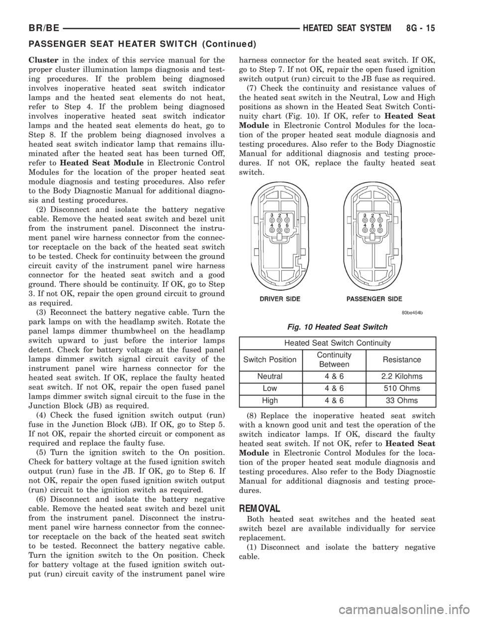
(7) Check the continuity and resistance values of
the heated seat switch in the Neutral, Low and High
positions as shown in the Heated Seat Switch Conti-
nuity chart (Fig. 10). If OK, refer toHeated Seat
Modulein Electronic Control Modules for the loca-
tion of the proper heated seat module diagnosis and
testing procedures. Also refer to the Body Diagnostic
Manual for additional diagnosis and testing proce-
dures. If not OK, replace the faulty heated seat
switch.
Heated Seat Switch Continuity
Switch PositionContinuity
BetweenResistance
Neutral 4 & 6 2.2 Kilohms
Low 4 & 6 510 Ohms
High 4 & 6 33 Ohms
(8) Replace the inoperative heated seat switch
with a known good unit and test the operation of the
switch indicator lamps. If OK, discard the faulty
heated seat switch. If not OK, refer toHeated Seat
Modulein Electronic Control Modules for the loca-
tion of the proper heated seat module diagnosis and
testing procedures. Also refer to the Body Diagnostic
Manual for additional diagnosis and testing proce-
dures.
REMOVAL
Both heated seat switches and the heated seat
switch bezel are available individually for service
replacement.
(1) Disconnect and isolate the battery negative
cable.
Fig. 10 Heated Seat Switch
BR/BEHEATED SEAT SYSTEM 8G - 15
PASSENGER SEAT HEATER SWITCH (Continued)
Page 569 of 2889
(2) Turn the exterior lamps On with the headlamp
switch. Rotate the headlamp switch panel lamps dim-
mer thumbwheel upward to just before the interior
lamps detent. Check for battery voltage at the panel
lamps dimmer fuse (Fuse5-5ampere) in the JB.
Rotate the panel lamps dimmer thumbwheel down-
ward while observing the test voltmeter. The reading
should go from battery voltage to zero volts. If OK,
go to Step 3. If not OK, repair the open panel lamps
dimmer switch signal circuit between the headlamp
switch and the JB as required.
(3) Turn the exterior lamps Off. Disconnect and
isolate the battery negative cable. Remove the instru-
ment cluster. Remove the instrument panel dimmer
fuse (Fuse5-5ampere) from the JB. Probe the
fused panel lamps dimmer switch signal circuit cav-
ity of the instrument panel wire harness connector
(Connector C2) for the instrument cluster. Check for
continuity to a good ground. There should be no con-
tinuity. If OK, go to Step 4. If not OK, repair the
shorted fused panel lamps dimmer switch signal cir-
cuit between the instrument cluster and the JB as
required.
(4) Reinstall the instrument panel dimmer fuse
(Fuse5-5ampere) in the JB. Reconnect the battery
negative cable. Turn the exterior lamps On with the
headlamp switch. Rotate the headlamp switch panel
lamps dimmer thumbwheel upward to just before the
interior lamps detent. Check for battery voltage at
the fused panel lamps dimmer switch signal circuit
cavity of the instrument panel wire harness connec-
tor (Connector C2) for the instrument cluster. If OK,
replace the faulty bulb and bulb holder units. If not
OK, repair the open fused panel lamps dimmer
switch signal circuit between the instrument cluster
and the JB as required.
REMOVAL
WARNING: ON VEHICLES EQUIPPED WITH AIR-
BAGS, DISABLE THE AIRBAG SYSTEM BEFORE
ATTEMPTING ANY STEERING WHEEL, STEERING
COLUMN, OR INSTRUMENT PANEL COMPONENT
DIAGNOSIS OR SERVICE. DISCONNECT AND ISO-
LATE THE BATTERY NEGATIVE (GROUND) CABLE,
THEN WAIT TWO MINUTES FOR THE AIRBAG SYS-
TEM CAPACITOR TO DISCHARGE BEFORE PER-
FORMING FURTHER DIAGNOSIS OR SERVICE. THIS
IS THE ONLY SURE WAY TO DISABLE THE AIRBAG
SYSTEM. FAILURE TO TAKE THE PROPER PRE-
CAUTIONS COULD RESULT IN ACCIDENTAL AIR-
BAG DEPLOYMENT AND POSSIBLE PERSONAL
INJURY.(1) Disconnect and isolate the battery negative
cable.
(2) Remove the cluster bezel from the instrument
panel. (Refer to 23 - BODY/INSTRUMENT PANEL/
CLUSTER BEZEL - REMOVAL).
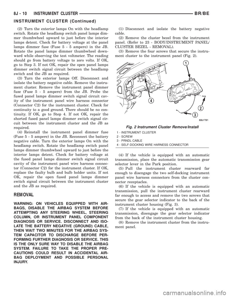
(3) Remove the four screws that secure the instru-
ment cluster to the instrument panel (Fig. 2).
(4) If the vehicle is equipped with an automatic
transmission, place the automatic transmission gear
selector lever in the Park position.
(5) Pull the instrument cluster rearward far
enough to disengage the two self-docking instrument
panel wire harness connectors from the cluster con-
nector receptacles.
(6) If the vehicle is equipped with an automatic
transmission, pull the instrument cluster rearward
far enough to access and remove the two screws that
secure the gear selector indicator to the back of the
instrument cluster housing (Fig. 3).
(7) If the vehicle is equipped with an automatic
transmission, disengage the gear selector indicator
from the back of the instrument cluster housing.
(8) Remove the instrument cluster from the instru-
ment panel.
Fig. 2 Instrument Cluster Remove/Install
1 - INSTRUMENT CLUSTER
2 - SCREW
3 - PRNDL CABLE
4 - SELF-DOCKING WIRE HARNESS CONNECTOR
8J - 10 INSTRUMENT CLUSTERBR/BE
INSTRUMENT CLUSTER (Continued)
Page 598 of 2889
LAMPS
TABLE OF CONTENTS
page page
LAMPS/LIGHTING - EXTERIOR............... 1LAMPS/LIGHTING - INTERIOR............... 33
LAMPS/LIGHTING - EXTERIOR
TABLE OF CONTENTS
page page
LAMPS/LIGHTING - EXTERIOR
DESCRIPTION............................2
OPERATION.............................2
DIAGNOSIS AND TESTING..................3
TURN SIGNAL & HAZARD WARNING
SYSTEM...............................3
SPECIFICATIONS.........................4
SPECIAL TOOLS..........................4
BRAKE LAMP SWITCH
DESCRIPTION............................4
OPERATION.............................4
DIAGNOSIS AND TESTING..................5
BRAKE LAMP SWITCH...................5
REMOVAL...............................5
INSTALLATION............................5
CENTER HIGH MOUNTED STOP LAMP
REMOVAL...............................6
INSTALLATION............................6
CENTER HIGH MOUNTED STOP LAMP UNIT
REMOVAL...............................6
INSTALLATION............................6
CLEARANCE LAMP
REMOVAL...............................6
INSTALLATION............................6
COMBINATION FLASHER
DESCRIPTION............................7
OPERATION.............................7
REMOVAL...............................8
INSTALLATION............................8
DAYTIME RUNNING LAMP MODULE
DESCRIPTION............................9
OPERATION.............................9
REMOVAL...............................9
INSTALLATION............................9
FOG LAMP
DIAGNOSIS AND TESTING..................9
FOG LAMP.............................9REMOVAL..............................11
INSTALLATION...........................11
FOG LAMP UNIT
REMOVAL..............................11
INSTALLATION...........................12
ADJUSTMENTS..........................12
HEADLAMP
DESCRIPTION...........................13
OPERATION.............................13
DIAGNOSIS AND TESTING.................13
HEADLAMP...........................13
REMOVAL..............................16
INSTALLATION...........................16
HEADLAMP RELAY
DESCRIPTION...........................16
OPERATION.............................17
DIAGNOSIS AND TESTING.................17
HEADLAMP RELAY.....................17
REMOVAL..............................18
INSTALLATION...........................18
HEADLAMP SWITCH
DESCRIPTION...........................18
OPERATION.............................18
DIAGNOSIS AND TESTING.................18
HEADLAMP SWITCH....................18
REMOVAL..............................19
INSTALLATION...........................20
HEADLAMP UNIT
REMOVAL..............................20
INSTALLATION...........................20
ADJUSTMENTS..........................21
LICENSE PLATE LAMP
REMOVAL..............................22
INSTALLATION...........................22
LICENSE PLATE LAMP UNIT
REMOVAL..............................22
INSTALLATION...........................22
BR/BELAMPS 8L - 1
Page 615 of 2889
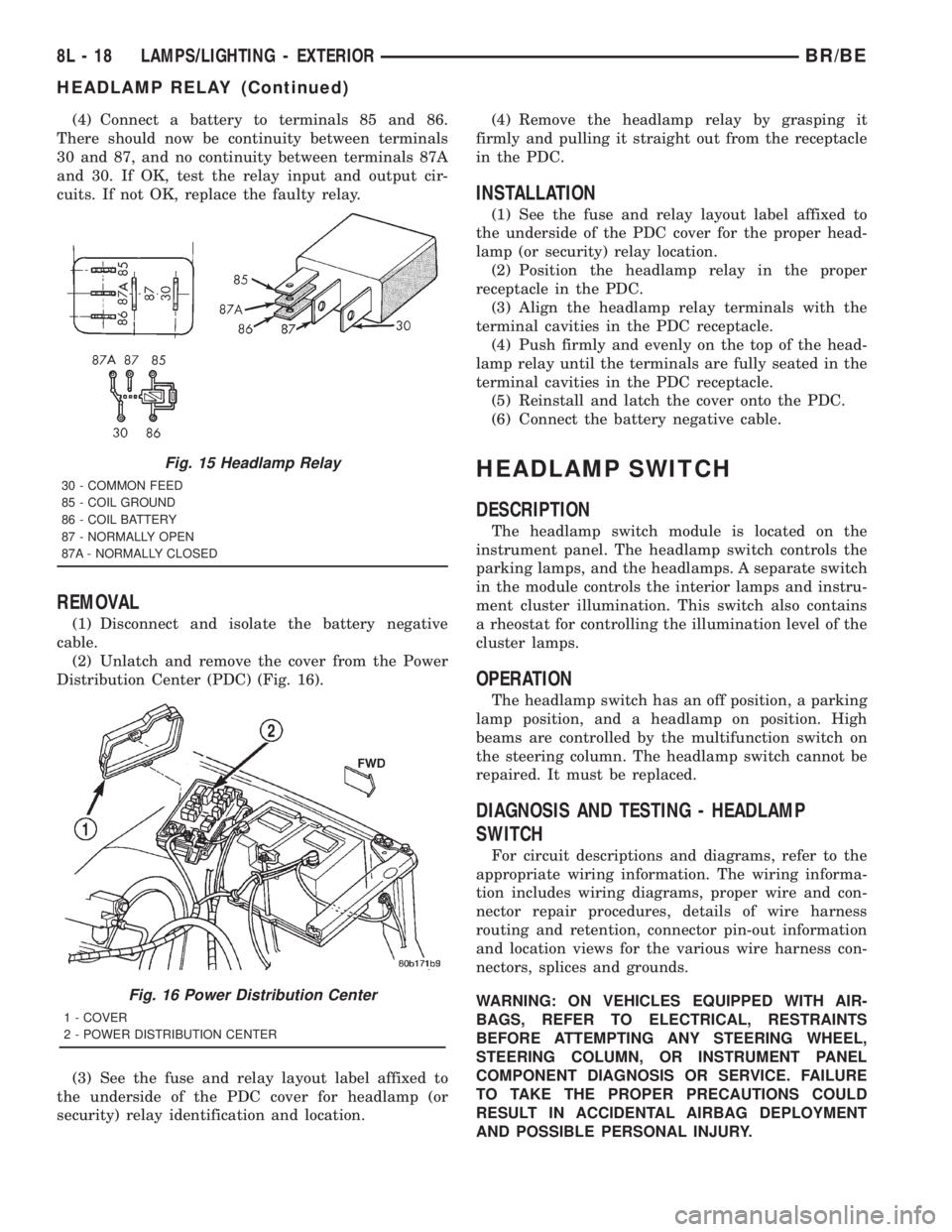
(4) Connect a battery to terminals 85 and 86.
There should now be continuity between terminals
30 and 87, and no continuity between terminals 87A
and 30. If OK, test the relay input and output cir-
cuits. If not OK, replace the faulty relay.
REMOVAL
(1) Disconnect and isolate the battery negative
cable.
(2) Unlatch and remove the cover from the Power
Distribution Center (PDC) (Fig. 16).
(3) See the fuse and relay layout label affixed to
the underside of the PDC cover for headlamp (or
security) relay identification and location.(4) Remove the headlamp relay by grasping it
firmly and pulling it straight out from the receptacle
in the PDC.
INSTALLATION
(1) See the fuse and relay layout label affixed to
the underside of the PDC cover for the proper head-
lamp (or security) relay location.
(2) Position the headlamp relay in the proper
receptacle in the PDC.
(3) Align the headlamp relay terminals with the
terminal cavities in the PDC receptacle.
(4) Push firmly and evenly on the top of the head-
lamp relay until the terminals are fully seated in the
terminal cavities in the PDC receptacle.
(5) Reinstall and latch the cover onto the PDC.
(6) Connect the battery negative cable.
HEADLAMP SWITCH
DESCRIPTION
The headlamp switch module is located on the
instrument panel. The headlamp switch controls the
parking lamps, and the headlamps. A separate switch
in the module controls the interior lamps and instru-
ment cluster illumination. This switch also contains
a rheostat for controlling the illumination level of the
cluster lamps.
OPERATION
The headlamp switch has an off position, a parking
lamp position, and a headlamp on position. High
beams are controlled by the multifunction switch on
the steering column. The headlamp switch cannot be
repaired. It must be replaced.
DIAGNOSIS AND TESTING - HEADLAMP
SWITCH
For circuit descriptions and diagrams, refer to the
appropriate wiring information. The wiring informa-
tion includes wiring diagrams, proper wire and con-
nector repair procedures, details of wire harness
routing and retention, connector pin-out information
and location views for the various wire harness con-
nectors, splices and grounds.
WARNING: ON VEHICLES EQUIPPED WITH AIR-
BAGS, REFER TO ELECTRICAL, RESTRAINTS
BEFORE ATTEMPTING ANY STEERING WHEEL,
STEERING COLUMN, OR INSTRUMENT PANEL
COMPONENT DIAGNOSIS OR SERVICE. FAILURE
TO TAKE THE PROPER PRECAUTIONS COULD
RESULT IN ACCIDENTAL AIRBAG DEPLOYMENT
AND POSSIBLE PERSONAL INJURY.
Fig. 15 Headlamp Relay
30 - COMMON FEED
85 - COIL GROUND
86 - COIL BATTERY
87 - NORMALLY OPEN
87A - NORMALLY CLOSED
Fig. 16 Power Distribution Center
1 - COVER
2 - POWER DISTRIBUTION CENTER
8L - 18 LAMPS/LIGHTING - EXTERIORBR/BE
HEADLAMP RELAY (Continued)
Page 630 of 2889
LAMPS/LIGHTING - INTERIOR
TABLE OF CONTENTS
page page
LAMPS/LIGHTING - INTERIOR
SPECIFICATIONS........................33
DOME LAMP
REMOVAL..............................33
INSTALLATION...........................33
DOOR AJAR SWITCH
DESCRIPTION...........................34
DIAGNOSIS AND TESTING.................34
DOOR AJAR SWITCH....................34
REMOVAL..............................35
INSTALLATION...........................35GLOVE BOX LAMP AND SWITCH
REMOVAL..............................35
INSTALLATION...........................35
READING LAMP
DESCRIPTION...........................36
OPERATION.............................36
REMOVAL..............................36
INSTALLATION...........................36
VANITY LAMP
REMOVAL..............................37
INSTALLATION...........................37
LAMPS/LIGHTING - INTERIOR
SPECIFICATIONS
INTERIOR LAMPS
LAMP BULB
A/C HEATER CONTROL 158
ASH RECEIVER 161
CIGAR LIGHTER 161
HEADLAMP SWITCH 158
HEATER CONTROL 158
INSTRUMENT CLUSTER PC194
RADIO ASC
AIRBAG HIGH LINE PC194
AIRBAG LOW LINE PC74
ANTI-LOCK BRAKE PC74
BATTERY VOLTAGE PC194
BRAKE WARNING PC194
CHECK ENGINE PC74
ENGINE OIL PRESSURE PC74
FOUR WHEEL DRIVE PC194
HIGH BEAM PC194
LOW FUEL PC194
LOW WASHER FLUID PC74
MAINTENANCE
REQUIREDPC74
MESSAGE CENTER PC194
SEAT BELT PC74
LAMP BULB
TURN SIGNAL PC194
UPSHIFT PC74
DOME 1004
GLOVE COMPARTMENT 1891
VANITY MIRROR LAMP P/N 6501966
DOME LAMP
REMOVAL
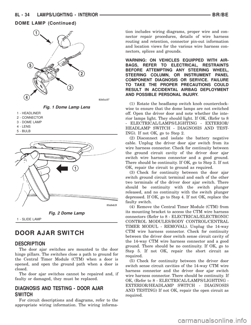
(1) Using a small flat blade, pry the left side (driv-
er's side) of the dome lamp lens downward from
dome lamp.
(2) Allow the lens to hang down (Fig. 1) , this will
disengage the right side of the lamp (passenger's
side) from the headliner.
(3) Pull the right side of the lamp down and slide
the lamp to the right (Fig. 2) .
(4) Separate the lamp from the headliner.
(5) Disengage dome lamp wire connector from body
wire harness.
(6) Separate dome lamp from vehicle.
INSTALLATION
(1) Position dome lamp at headliner.
(2) Connect dome lamp wire connector to body
wire harness.
(3) Position the left side of the lamp in the head-
liner opening and slide lamp to the left.
(4) Push the right side of the lamp in the head-
liner opening and push the lamp lens up into the
lamp to secure.
BR/BELAMPS/LIGHTING - INTERIOR 8L - 33
Page 631 of 2889
DOOR AJAR SWITCH
DESCRIPTION
The door ajar switches are mounted to the door
hinge pillars. The switches close a path to ground for
the Central Timer Module (CTM) when a door is
opened, and open the ground path when a door is
closed.
The door ajar switches cannot be repaired and, if
faulty or damaged, they must be replaced.
DIAGNOSIS AND TESTING - DOOR AJAR
SWITCH
For circuit descriptions and diagrams, refer to the
appropriate wiring information. The wiring informa-tion includes wiring diagrams, proper wire and con-
nector repair procedures, details of wire harness
routing and retention, connector pin-out information
and location views for the various wire harness con-
nectors, splices and grounds.
WARNING: ON VEHICLES EQUIPPED WITH AIR-
BAGS, REFER TO ELECTRICAL, RESTRAINTS
BEFORE ATTEMPTING ANY STEERING WHEEL,
STEERING COLUMN, OR INSTRUMENT PANEL
COMPONENT DIAGNOSIS OR SERVICE. FAILURE
TO TAKE THE PROPER PRECAUTIONS COULD
RESULT IN ACCIDENTAL AIRBAG DEPLOYMENT
AND POSSIBLE PERSONAL INJURY.
(1) Rotate the headlamp switch knob counterclock-
wise to ensure that the dome lamps are not switched
off. Open the driver door and note whether the inte-
rior lamps light. They should light. If OK, (Refer to 8
- ELECTRICAL/LAMPS/LIGHTING - EXTERIOR/
HEADLAMP SWITCH - DIAGNOSIS AND TEST-
ING). If not OK, go to Step 2.
(2) Disconnect and isolate the battery negative
cable. Unplug the driver door ajar switch from its
wire harness connector. Check for continuity between
the ground circuit cavity of the driver door ajar
switch wire harness connector and a good ground.
There should be continuity. If OK, go to Step 3. If not
OK, repair the circuit to ground as required.
(3) Check for continuity between the door ajar
switch ground circuit terminal and each of the other
two terminals of the driver door ajar switch. There
should be continuity with the switch plunger
released, and no continuity with the switch plunger
depressed. If OK, go to Step 4. If not OK, replace the
faulty switch.
(4) Remove the Central Timer Module (CTM) from
its mounting bracket to access the CTM wire harness
connectors (Refer to 8 - ELECTRICAL/ELECTRONIC
CONTROL MODULES/BODY CONTROL/CENTRAL
TIMER MODUL - REMOVAL). Unplug the 14-way
CTM wire harness connector. Check for continuity
between the driver door switch sense circuit cavity of
the 14-way CTM wire harness connector and a good
ground. There should be no continuity. If OK, go to
Step 5. If not OK, repair the short circuit as
required.
(5) Check for continuity between the driver door
switch sense circuit cavities of the 14-way CTM wire
harness connector and the driver door ajar switch
wire harness connector. There should be continuity. If
OK, (Refer to 8 - ELECTRICAL/LAMPS/LIGHTING -
EXTERIOR/HEADLAMP SWITCH - DIAGNOSIS
AND TESTING) If not OK, repair the open circuit as
required.
Fig. 1 Dome Lamp Lens
1 - HEADLINER
2 - CONNECTOR
3 - DOME LAMP
4 - LENS
5 - BULB
Fig. 2 Dome Lamp
1 - SLIDE LAMP
8L - 34 LAMPS/LIGHTING - INTERIORBR/BE
DOME LAMP (Continued)
Page 632 of 2889
REMOVAL
(1) Disconnect and isolate the battery negative
cable.
(2) Grasp the body of the door ajar switch with a
pair of pliers and move the switch gently back-and-
forth while pulling it out of the door hinge pillar
mounting hole.
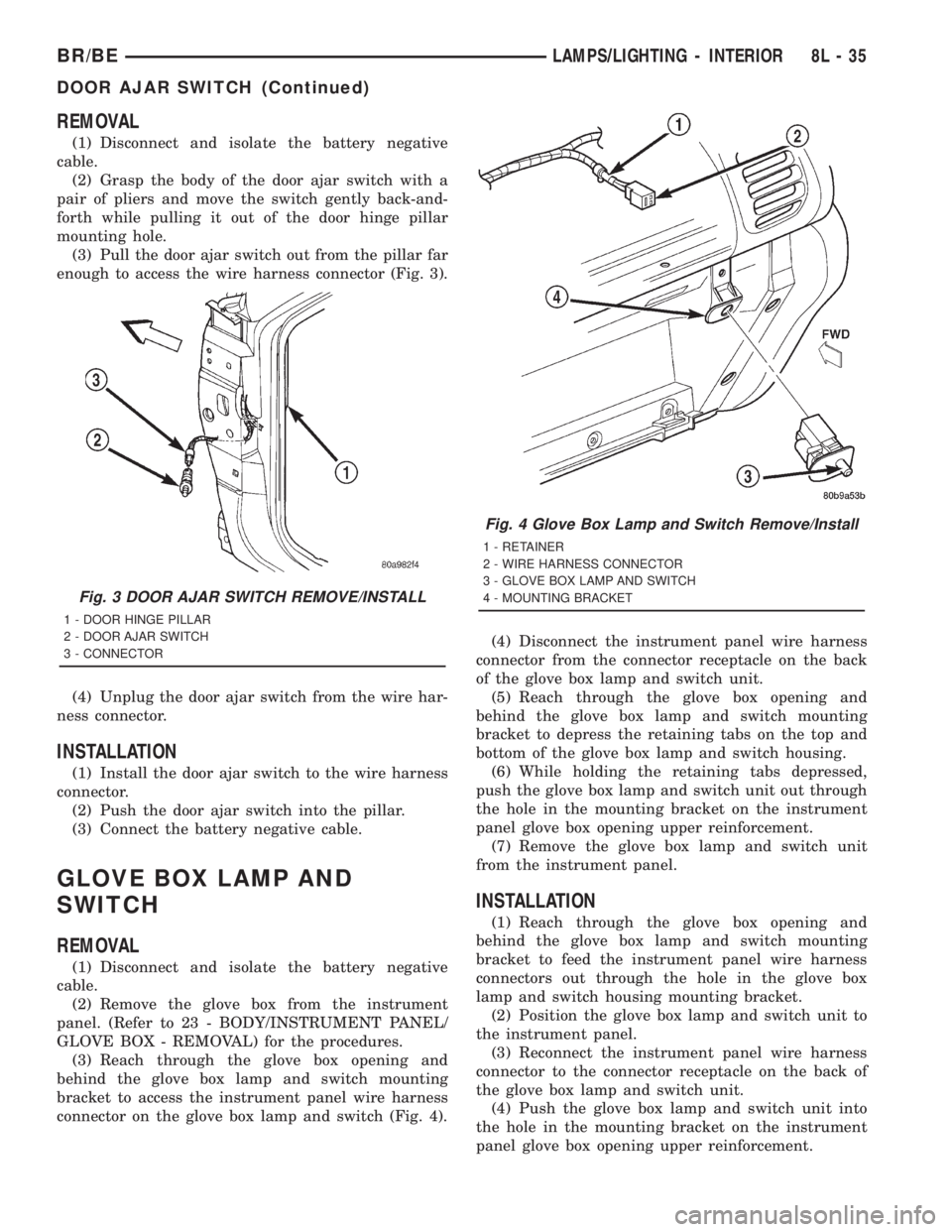
(3) Pull the door ajar switch out from the pillar far
enough to access the wire harness connector (Fig. 3).
(4) Unplug the door ajar switch from the wire har-
ness connector.
INSTALLATION
(1) Install the door ajar switch to the wire harness
connector.
(2) Push the door ajar switch into the pillar.
(3) Connect the battery negative cable.
GLOVE BOX LAMP AND
SWITCH
REMOVAL
(1) Disconnect and isolate the battery negative
cable.
(2) Remove the glove box from the instrument
panel. (Refer to 23 - BODY/INSTRUMENT PANEL/
GLOVE BOX - REMOVAL) for the procedures.
(3) Reach through the glove box opening and
behind the glove box lamp and switch mounting
bracket to access the instrument panel wire harness
connector on the glove box lamp and switch (Fig. 4).(4) Disconnect the instrument panel wire harness
connector from the connector receptacle on the back
of the glove box lamp and switch unit.
(5) Reach through the glove box opening and
behind the glove box lamp and switch mounting
bracket to depress the retaining tabs on the top and
bottom of the glove box lamp and switch housing.
(6) While holding the retaining tabs depressed,
push the glove box lamp and switch unit out through
the hole in the mounting bracket on the instrument
panel glove box opening upper reinforcement.
(7) Remove the glove box lamp and switch unit
from the instrument panel.
INSTALLATION
(1) Reach through the glove box opening and
behind the glove box lamp and switch mounting
bracket to feed the instrument panel wire harness
connectors out through the hole in the glove box
lamp and switch housing mounting bracket.
(2) Position the glove box lamp and switch unit to
the instrument panel.
(3) Reconnect the instrument panel wire harness
connector to the connector receptacle on the back of
the glove box lamp and switch unit.
(4) Push the glove box lamp and switch unit into
the hole in the mounting bracket on the instrument
panel glove box opening upper reinforcement.
Fig. 3 DOOR AJAR SWITCH REMOVE/INSTALL
1 - DOOR HINGE PILLAR
2 - DOOR AJAR SWITCH
3 - CONNECTOR
Fig. 4 Glove Box Lamp and Switch Remove/Install
1 - RETAINER
2 - WIRE HARNESS CONNECTOR
3 - GLOVE BOX LAMP AND SWITCH
4 - MOUNTING BRACKET
BR/BELAMPS/LIGHTING - INTERIOR 8L - 35
DOOR AJAR SWITCH (Continued)