2001 DODGE RAM interior
[x] Cancel search: interiorPage 2012 of 2889
(2) Install new seals in the clutch retainer lower
groove and on the outer diameter of the retainer hub.
Be sure lip of each seal faces interior of clutch
retainer.
(3) Lubricate lips of the retainer seals with liberal
quantity of MopartDoor Ease. Then lubricate
retainer hub, bore, and piston with light coat of
transmission fluid.
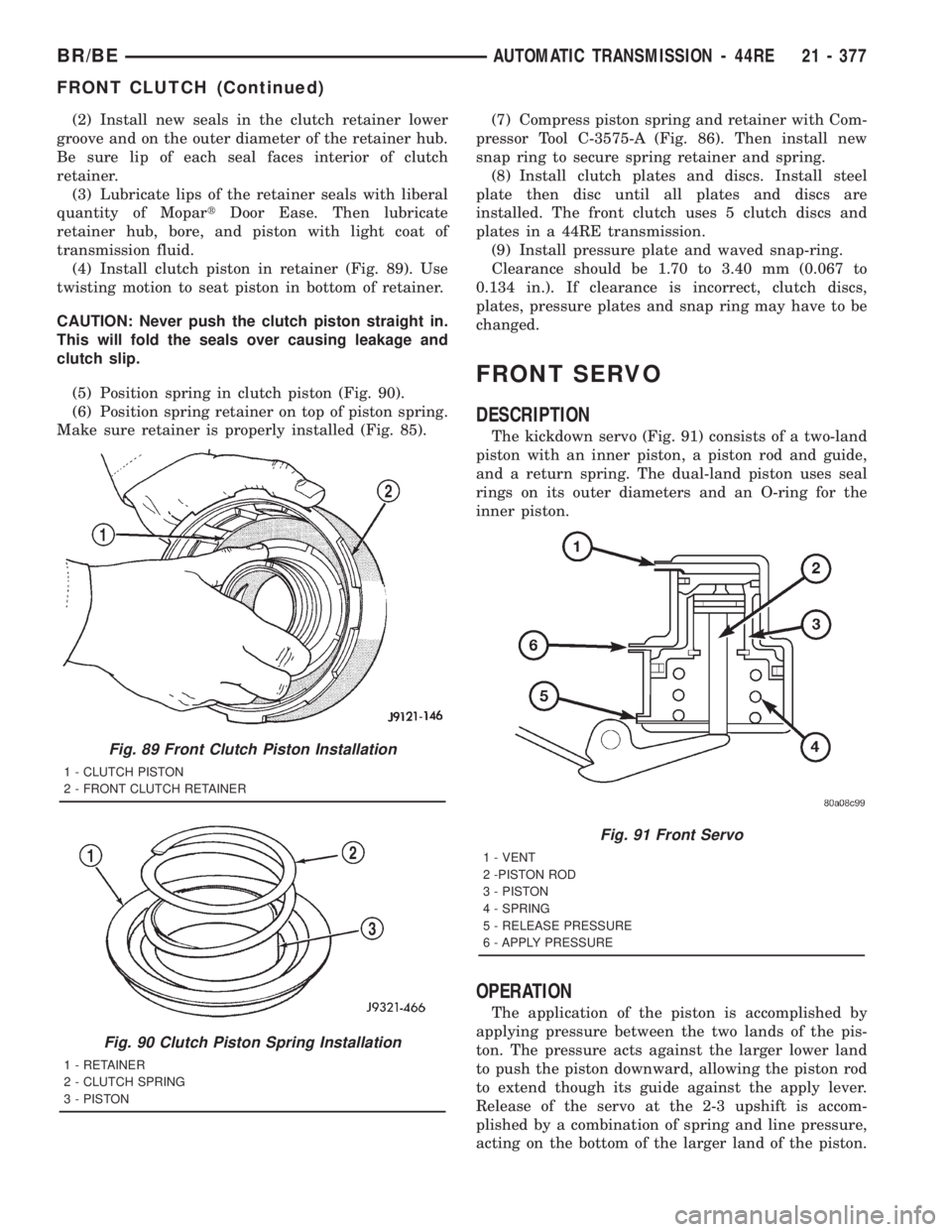
(4) Install clutch piston in retainer (Fig. 89). Use
twisting motion to seat piston in bottom of retainer.
CAUTION: Never push the clutch piston straight in.
This will fold the seals over causing leakage and
clutch slip.
(5) Position spring in clutch piston (Fig. 90).
(6) Position spring retainer on top of piston spring.
Make sure retainer is properly installed (Fig. 85).(7) Compress piston spring and retainer with Com-
pressor Tool C-3575-A (Fig. 86). Then install new
snap ring to secure spring retainer and spring.
(8) Install clutch plates and discs. Install steel
plate then disc until all plates and discs are
installed. The front clutch uses 5 clutch discs and
plates in a 44RE transmission.
(9) Install pressure plate and waved snap-ring.
Clearance should be 1.70 to 3.40 mm (0.067 to
0.134 in.). If clearance is incorrect, clutch discs,
plates, pressure plates and snap ring may have to be
changed.
FRONT SERVO
DESCRIPTION
The kickdown servo (Fig. 91) consists of a two-land
piston with an inner piston, a piston rod and guide,
and a return spring. The dual-land piston uses seal
rings on its outer diameters and an O-ring for the
inner piston.
OPERATION
The application of the piston is accomplished by
applying pressure between the two lands of the pis-
ton. The pressure acts against the larger lower land
to push the piston downward, allowing the piston rod
to extend though its guide against the apply lever.
Release of the servo at the 2-3 upshift is accom-
plished by a combination of spring and line pressure,
acting on the bottom of the larger land of the piston.
Fig. 89 Front Clutch Piston Installation
1 - CLUTCH PISTON
2 - FRONT CLUTCH RETAINER
Fig. 90 Clutch Piston Spring Installation
1 - RETAINER
2 - CLUTCH SPRING
3 - PISTON
Fig. 91 Front Servo
1 - VENT
2 -PISTON ROD
3 - PISTON
4 - SPRING
5 - RELEASE PRESSURE
6 - APPLY PRESSURE
BR/BEAUTOMATIC TRANSMISSION - 44RE 21 - 377
FRONT CLUTCH (Continued)
Page 2054 of 2889

INSPECTION
Replace the clutch discs if warped, worn, scored,
burned/charred, the lugs are damaged, or if the fac-
ing is flaking off. Replace the top and bottom pres-
sure plates if scored, warped, or cracked. Be sure the
driving lugs on the pressure and clutch plates are
also in good condition. The lugs must not be bent,
cracked or damaged in any way.
Replace the piston spring and wave spring if either
part is distorted, warped or broken.
Check the lug grooves in the clutch retainer. The
clutch and pressure plates should slide freely in the
slots. Replace the retainer if the grooves are worn or
damaged. Also check action of the check balls in the
retainer and piston. Each check ball must move
freely and not stick.
Replace the retainer bushing if worn, scored, or
doubt exists about bushing condition.
Inspect the piston and retainer seal surfaces for
nicks or scratches. Minor scratches can be removed
with crocus cloth. However, replace the piston and/or
retainer if the seal surfaces are seriously scored.
Check condition of the fiber thrust washer and
metal output shaft thrust washer. Replace either
washer if worn or damaged.
Check condition of the seal rings on the input shaft
and clutch retainer hub. Replace the seal rings only
if worn, distorted, or damaged. The input shaft front
seal ring is teflon with chamfered ends. The rear ring
is metal with interlocking ends.
Check the input shaft for wear, or damage. Replace
the shaft if worn, scored or damaged in any way.
ASSEMBLY
(1) Soak clutch discs in transmission fluid while
assembling other clutch parts.
(2) Install new seal rings on clutch retainer hub
and input shaft, if necessary, (Fig. 216) and (Fig.
217).
(a) Be sure clutch hub seal ring is fully seated in
groove and is not twisted.
(3) Lubricate splined end of input shaft and clutch
retainer with transmission fluid. Then press input
shaft into retainer (Fig. 218). Use a suitably sized
press tool to support retainer as close to input shaft
as possible.
(4) Install input shaft snap-ring (Fig. 217).
(5) Invert retainer and press input shaft in oppo-
site direction until snap-ring is seated.
(6) Install new seals on clutch piston. Be sure lip
of each seal faces interior of clutch retainer.
(7) Lubricate lip of piston seals with generous
quantity of MopartDoor Ease. Then lubricate
retainer hub and bore with light coat of transmission
fluid.
(8) Install clutch piston in retainer. Use twisting
motion to seat piston in bottom of retainer. A thin
strip of plastic (about 0.0209thick), can be used to
guide seals into place if necessary.
CAUTION: Never push the clutch piston straight in.
This will fold the seals over causing leakage and
clutch slip. In addition, never use any type of metal
tool to help ease the piston seals into place. Metal
tools will cut, shave, or score the seals.
(9) Install piston spring in retainer and on top of
piston (Fig. 219). Concave side of spring faces down-
ward (toward piston).
(10) Install wave spring in retainer (Fig. 219). Be
sure spring is completely seated in retainer groove.
(11) Install bottom pressure plate (Fig. 216).
Ridged side of plate faces downward (toward piston)
and flat side toward clutch pack.
(12) Install first clutch disc in retainer on top of
bottom pressure plate. Then install a clutch plate fol-
lowed by a clutch disc until entire clutch pack is
installed (4 discs and 3 plates are required) (Fig.
216).
(13) Install top pressure plate.
(14) Install selective snap-ring. Be sure snap-ring
is fully seated in retainer groove.
Fig. 215 Removing Input Shaft Snap-Ring
1 - REAR CLUTCH RETAINER
2 - INPUT SHAFT SNAP-RING
3 - SNAP-RING PLIERS
BR/BEAUTOMATIC TRANSMISSION - 44RE 21 - 419
REAR CLUTCH (Continued)
Page 2100 of 2889
CLEANING
Clean the valve housings, valves, plugs, springs,
and separator plates with a standard parts cleaning
solution only. Do not use gasoline, kerosene, or any
type of caustic solution.
Do not immerse any of the electrical components in
cleaning solution. Clean the governor solenoid and
sensor and the dual solenoid and harness assembly
by wiping them off with dry shop towels only.
Dry all except the electrical parts with compressed
air. Make sure all passages are clean and free from
obstructions.Do not use rags or shop towels to
dry or wipe off valve body components. Lint
from these materials can stick to valve body
parts, interfere with valve operation, and clog
filters and fluid passages.
Wipe the governor pressure sensor and solenoid
valve with dry, lint free shop towels only. The O-rings
on the sensor and solenoid valve are the only service-
able components. Be sure the vent ports in the sole-
noid valve are open and not blocked by dirt or debris.
Replace the valve and/or sensor only when DRB scan
tool diagnosis indicates this is necessary. Or, if either
part has sustained physical damage (dented,
deformed, broken, etc.).
CAUTION: Do not turn the small screw at the end of
the solenoid valve for any reason. Turning the
screw in either direction will ruin solenoid calibra-
tion and result in solenoid failure. In addition, the
filter on the solenoid valve is NOT serviceable. Do
not try to remove the filter as this will damage the
valve housing.
INSPECTION
Inspect the throttle and manual valve levers and
shafts. Do not attempt to straighten a bent shaft or
correct a loose lever. Replace these components if
worn, bent, loose or damaged in any way.
Inspect all of the valve body mating surfaces for
scratches, nicks, burrs, or distortion. Use a straight-
edge to check surface flatness. Minor scratches may
be removed with crocus cloth using only very light
pressure.
Minor distortion of a valve body mating surface
may be corrected by smoothing the surface with a
sheet of crocus cloth. Position the crocus cloth on a
surface plate, sheet of plate glass or equally flat sur-
face. If distortion is severe or any surfaces are
heavily scored, the valve body will have to be
replaced.
CAUTION: Many of the valves and plugs, such as
the throttle valve, shuttle valve plug, 1-2 shift valve
and 1-2 governor plug, are made of coated alumi-
num. Aluminum components are identified by the
dark color of the special coating applied to the sur-
face (or by testing with a magnet). Do not sand alu-
minum valves or plugs under any circumstances.
This practice could damage the special coating
causing the valves/plugs to stick and bind.
Inspect the valves and plugs for scratches, burrs,
nicks, or scores. Minor surface scratches on steel
valves and plugs can be removed with crocus cloth
butdo not round off the edges of the valve or
plug lands.Maintaining sharpness of these edges is
vitally important. The edges prevent foreign matter
from lodging between the valves and plugs and the
bore.
Inspect all the valve and plug bores in the valve
body. Use a penlight to view the bore interiors.
Replace the valve body if any bores are distorted or
scored. Inspect all of the valve body springs. The
springs must be free of distortion, warpage or broken
coils.
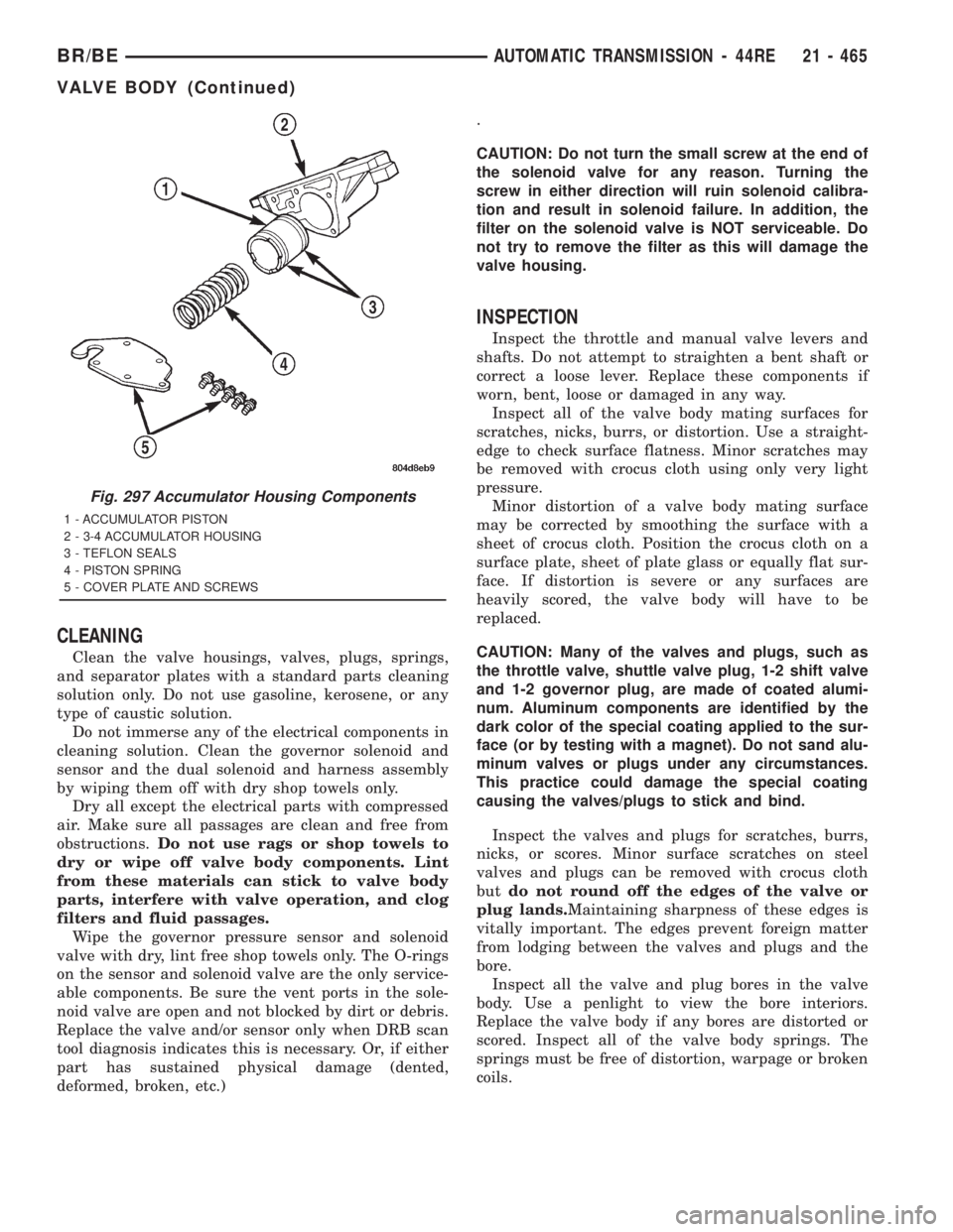
Fig. 297 Accumulator Housing Components
1 - ACCUMULATOR PISTON
2 - 3-4 ACCUMULATOR HOUSING
3 - TEFLON SEALS
4 - PISTON SPRING
5 - COVER PLATE AND SCREWS
BR/BEAUTOMATIC TRANSMISSION - 44RE 21 - 465
VALVE BODY (Continued)
Page 2185 of 2889
INSPECTION
Inspect the front clutch components. Replace the
clutch discs if warped, worn, scored, burned or
charred, the lugs are damaged, or if the facing is
flaking off. Replace the steel plates and reaction
plate if heavily scored, warped, or broken. Be sure
the driving lugs on the discs and plate are also in
good condition. The lugs must not be bent, cracked or
damaged in any way.
Replace the piston springs and spring retainer if
either are distorted, warped or broken.
Check the lug grooves in the clutch piston retainer.
The steel plates should slide freely in the slots.
Replace the piston retainer if the grooves are worn or
damaged. Also check action of the check ball in the
piston retainer. The ball must move freely and not
stick.
Replace the retainer bushing if worn, scored, or
there is any doubt about bushing condition.
Inspect the piston and retainer seal surfaces for
nicks or scratches. Minor scratches can be removed
with crocus cloth. However, replace the piston and/or
retainer if the seal surfaces are seriously scored.
Check the clutch piston check ball. The ball should
be securely in place. Replace the piston if the ball is
missing, or seized in place.
ASSEMBLY
NOTE: The 46RE transmission uses three plates
and discs for the front clutch.
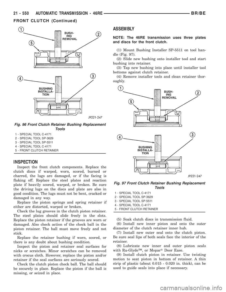
(1) Mount Bushing Installer SP-5511 on tool han-
dle (Fig. 97).
(2) Slide new bushing onto installer tool and start
bushing into retainer.
(3) Tap new bushing into place until installer tool
bottoms against clutch retainer.
(4) Remove installer tools and clean retainer thor-
oughly.
(5) Soak clutch discs in transmission fluid.
(6) Install new inner piston seal onto the outer
diameter of the clutch retainer inner hub.
(7) Install new outer seal onto the clutch piston.
Be sure seal lips of both seals face the interior of the
retainer.
(8) Lubricate new inner and outer piston seals
with Ru-GlydeŸ, or MopartDoor Ease.
(9) Install clutch piston in retainer. Use twisting
motion to seat piston in bottom of retainer. A thin
strip of plastic (about 0.015 - 0.020 in. thick), can be
used to guide seals into place if necessary.
Fig. 96 Front Clutch Retainer Bushing Replacement
Tools
1 - SPECIAL TOOL C-4171
2 - SPECIAL TOOL SP-3629
3 - SPECIAL TOOL SP-5511
4 - SPECIAL TOOL C-4171
5 - FRONT CLUTCH RETAINER
Fig. 97 Front Clutch Retainer Bushing Replacement
Tools
1 - SPECIAL TOOL C-4171
2 - SPECIAL TOOL SP-3629
3 - SPECIAL TOOL SP-5511
4 - SPECIAL TOOL C-4171
5 - FRONT CLUTCH RETAINER
21 - 550 AUTOMATIC TRANSMISSION - 46REBR/BE
FRONT CLUTCH (Continued)
Page 2228 of 2889
CLEANING
Clean the clutch components with solvent and dry
them with compressed air. Do not use rags or shop
towels to dry any of the clutch parts. Lint from such
materials will adhere to component surfaces and
could restrict or block fluid passages after assembly.
INSPECTION
Replace the clutch discs if warped, worn, scored,
burned/charred, the lugs are damaged, or if the fac-
ing is flaking off. Replace the top and bottom pres-
sure plates if scored, warped, or cracked. Be sure the
driving lugs on the pressure and clutch plates are
also in good condition. The lugs must not be bent,
cracked or damaged in any way.
Replace the piston spring and wave spring if either
part is distorted, warped or broken.
Check the lug grooves in the clutch retainer. The
clutch and pressure plates should slide freely in the
slots. Replace the retainer if the grooves are worn or
damaged. Also check action of the check balls in the
retainer and piston. Each check ball must move
freely and not stick.
Replace the retainer bushing if worn, scored, or
doubt exists about bushing condition.
Inspect the piston and retainer seal surfaces for
nicks or scratches. Minor scratches can be removed
with crocus cloth. However, replace the piston and/or
retainer if the seal surfaces are seriously scored.
Check condition of the fiber thrust washer and
metal output shaft thrust washer. Replace either
washer if worn or damaged.
Check condition of the seal rings on the input shaft
and clutch retainer hub. Replace the seal rings only
if worn, distorted, or damaged. The input shaft front
seal ring is teflon with chamfered ends. The rear ring
is metal with interlocking ends.
Check the input shaft for wear, or damage. Replace
the shaft if worn, scored or damaged in any way.
ASSEMBLY
(1) Soak clutch discs in transmission fluid while
assembling other clutch parts.
(2) Install new seal rings on clutch retainer hub
and input shaft if necessary.
(a) Be sure clutch hub seal ring is fully seated in
groove and is not twisted.
(3) Lubricate splined end of input shaft and clutch
retainer with transmission fluid. Then partially press
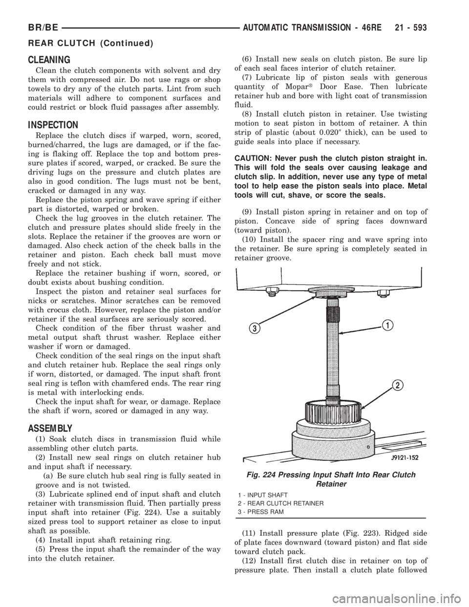
input shaft into retainer (Fig. 224). Use a suitably
sized press tool to support retainer as close to input
shaft as possible.
(4) Install input shaft retaining ring.
(5) Press the input shaft the remainder of the way
into the clutch retainer.(6) Install new seals on clutch piston. Be sure lip
of each seal faces interior of clutch retainer.
(7) Lubricate lip of piston seals with generous
quantity of MopartDoor Ease. Then lubricate
retainer hub and bore with light coat of transmission
fluid.
(8) Install clutch piston in retainer. Use twisting
motion to seat piston in bottom of retainer. A thin
strip of plastic (about 0.0209thick), can be used to
guide seals into place if necessary.
CAUTION: Never push the clutch piston straight in.
This will fold the seals over causing leakage and
clutch slip. In addition, never use any type of metal
tool to help ease the piston seals into place. Metal
tools will cut, shave, or score the seals.
(9) Install piston spring in retainer and on top of
piston. Concave side of spring faces downward
(toward piston).
(10) Install the spacer ring and wave spring into
the retainer. Be sure spring is completely seated in
retainer groove.
(11) Install pressure plate (Fig. 223). Ridged side
of plate faces downward (toward piston) and flat side
toward clutch pack.
(12) Install first clutch disc in retainer on top of
pressure plate. Then install a clutch plate followed
Fig. 224 Pressing Input Shaft Into Rear Clutch
Retainer
1 - INPUT SHAFT
2 - REAR CLUTCH RETAINER
3 - PRESS RAM
BR/BEAUTOMATIC TRANSMISSION - 46RE 21 - 593
REAR CLUTCH (Continued)
Page 2272 of 2889
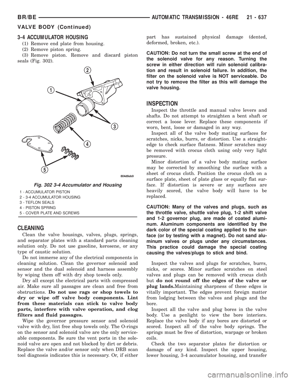
3-4 ACCUMULATOR HOUSING
(1) Remove end plate from housing.
(2) Remove piston spring.
(3) Remove piston. Remove and discard piston
seals (Fig. 302).
CLEANING
Clean the valve housings, valves, plugs, springs,
and separator plates with a standard parts cleaning
solution only. Do not use gasoline, kerosene, or any
type of caustic solution.
Do not immerse any of the electrical components in
cleaning solution. Clean the governor solenoid and
sensor and the dual solenoid and harness assembly
by wiping them off with dry shop towels only.
Dry all except the electrical parts with compressed
air. Make sure all passages are clean and free from
obstructions.Do not use rags or shop towels to
dry or wipe off valve body components. Lint
from these materials can stick to valve body
parts, interfere with valve operation, and clog
filters and fluid passages.
Wipe the governor pressure sensor and solenoid
valve with dry, lint free shop towels only. The O-rings
on the sensor and solenoid valve are the only service-
able components. Be sure the vent ports in the sole-
noid valve are open and not blocked by dirt or debris.
Replace the valve and/or sensor only when DRB scan
tool diagnosis indicates this is necessary. Or, if eitherpart has sustained physical damage (dented,
deformed, broken, etc.).
CAUTION: Do not turn the small screw at the end of
the solenoid valve for any reason. Turning the
screw in either direction will ruin solenoid calibra-
tion and result in solenoid failure. In addition, the
filter on the solenoid valve is NOT serviceable. Do
not try to remove the filter as this will damage the
valve housing.
INSPECTION
Inspect the throttle and manual valve levers and
shafts. Do not attempt to straighten a bent shaft or
correct a loose lever. Replace these components if
worn, bent, loose or damaged in any way.
Inspect all of the valve body mating surfaces for
scratches, nicks, burrs, or distortion. Use a straight-
edge to check surface flatness. Minor scratches may
be removed with crocus cloth using only very light
pressure.
Minor distortion of a valve body mating surface
may be corrected by smoothing the surface with a
sheet of crocus cloth. Position the crocus cloth on a
surface plate, sheet of plate glass or equally flat sur-
face. If distortion is severe or any surfaces are
heavily scored, the valve body will have to be
replaced.
CAUTION: Many of the valves and plugs, such as
the throttle valve, shuttle valve plug, 1-2 shift valve
and 1-2 governor plug, are made of coated alumi-
num. Aluminum components are identified by the
dark color of the special coating applied to the sur-
face (or by testing with a magnet). Do not sand alu-
minum valves or plugs under any circumstances.
This practice could damage the special coating
causing the valves/plugs to stick and bind.
Inspect the valves and plugs for scratches, burrs,
nicks, or scores. Minor surface scratches on steel
valves and plugs can be removed with crocus cloth
butdo not round off the edges of the valve or
plug lands.Maintaining sharpness of these edges is
vitally important. The edges prevent foreign matter
from lodging between the valves and plugs and the
bore.
Inspect all the valve and plug bores in the valve
body. Use a penlight to view the bore interiors.
Replace the valve body if any bores are distorted or
scored. Inspect all of the valve body springs. The
springs must be free of distortion, warpage or broken
coils.
Check the two separator plates for distortion or
damage of any kind. Inspect the upper housing,
lower housing, 3-4 accumulator housing, and transfer
Fig. 302 3-4 Accumulator and Housing
1 - ACCUMULATOR PISTON
2 - 3-4 ACCUMULATOR HOUSING
3 - TEFLON SEALS
4 - PISTON SPRING
5 - COVER PLATE AND SCREWS
BR/BEAUTOMATIC TRANSMISSION - 46RE 21 - 637
VALVE BODY (Continued)
Page 2356 of 2889
INSPECTION
Inspect the front clutch components. Replace the
clutch discs if warped, worn, scored, burned or
charred, the lugs are damaged, or if the facing is
flaking off. Replace the steel plates and reaction
plate if heavily scored, warped, or broken. Be sure
the driving lugs on the discs and plate are also in
good condition. The lugs must not be bent, cracked or
damaged in any way.
Replace the piston springs and spring retainer if
either are distorted, warped or broken.
Check the lug grooves in the clutch piston retainer.
The steel plates should slide freely in the slots.
Replace the piston retainer if the grooves are worn or
damaged. Also check action of the check ball in the
piston retainer. The ball must move freely and not
stick.
Replace the retainer bushing if worn, scored, or
there is any doubt about bushing condition.
Inspect the piston and retainer seal surfaces for
nicks or scratches. Minor scratches can be removed
with crocus cloth. However, replace the piston and/or
retainer if the seal surfaces are seriously scored.
Check the clutch piston check ball. The ball should
be securely in place. Replace the piston if the ball is
missing, or seized in place.
ASSEMBLY
NOTE: The 47RE transmission uses four plates and
discs for the front clutch.
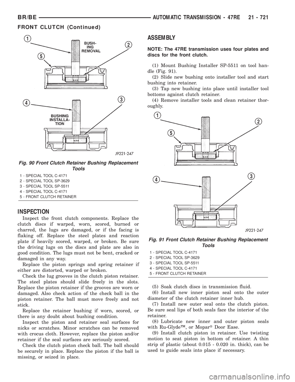
(1) Mount Bushing Installer SP-5511 on tool han-
dle (Fig. 91).
(2) Slide new bushing onto installer tool and start
bushing into retainer.
(3) Tap new bushing into place until installer tool
bottoms against clutch retainer.
(4) Remove installer tools and clean retainer thor-
oughly.
(5) Soak clutch discs in transmission fluid.
(6) Install new inner piston seal onto the outer
diameter of the clutch retainer inner hub.
(7) Install new outer seal onto the clutch piston.
Be sure seal lips of both seals face the interior of the
retainer.
(8) Lubricate new inner and outer piston seals
with Ru-GlydeŸ, or MopartDoor Ease.
(9) Install clutch piston in retainer. Use twisting
motion to seat piston in bottom of retainer. A thin
strip of plastic (about 0.015 - 0.020 in. thick), can be
used to guide seals into place if necessary.
Fig. 90 Front Clutch Retainer Bushing Replacement
Tools
1 - SPECIAL TOOL C-4171
2 - SPECIAL TOOL SP-3629
3 - SPECIAL TOOL SP-5511
4 - SPECIAL TOOL C-4171
5 - FRONT CLUTCH RETAINER
Fig. 91 Front Clutch Retainer Bushing Replacement
Tools
1 - SPECIAL TOOL C-4171
2 - SPECIAL TOOL SP-3629
3 - SPECIAL TOOL SP-5511
4 - SPECIAL TOOL C-4171
5 - FRONT CLUTCH RETAINER
BR/BEAUTOMATIC TRANSMISSION - 47RE 21 - 721
FRONT CLUTCH (Continued)
Page 2401 of 2889
Inspect the piston and retainer seal surfaces for
nicks or scratches. Minor scratches can be removed
with crocus cloth. However, replace the piston and/or
retainer if the seal surfaces are seriously scored.
Check condition of the fiber thrust washer and
metal output shaft thrust washer. Replace either
washer if worn or damaged.
Check condition of the seal rings on the input shaft
and clutch retainer hub. Replace the seal rings only
if worn, distorted, or damaged. The input shaft front
seal ring is teflon with chamfered ends. The rear ring
is metal with interlocking ends.
Check the input shaft for wear, or damage. Replace
the shaft if worn, scored or damaged in any way.
ASSEMBLY
(1) Soak clutch discs in transmission fluid while
assembling other clutch parts.
(2) Install new seal rings on clutch retainer hub
and input shaft if necessary.
(a) Be sure clutch hub seal ring is fully seated in
groove and is not twisted.
(3) Lubricate splined end of input shaft and clutch
retainer with transmission fluid. Then partially press
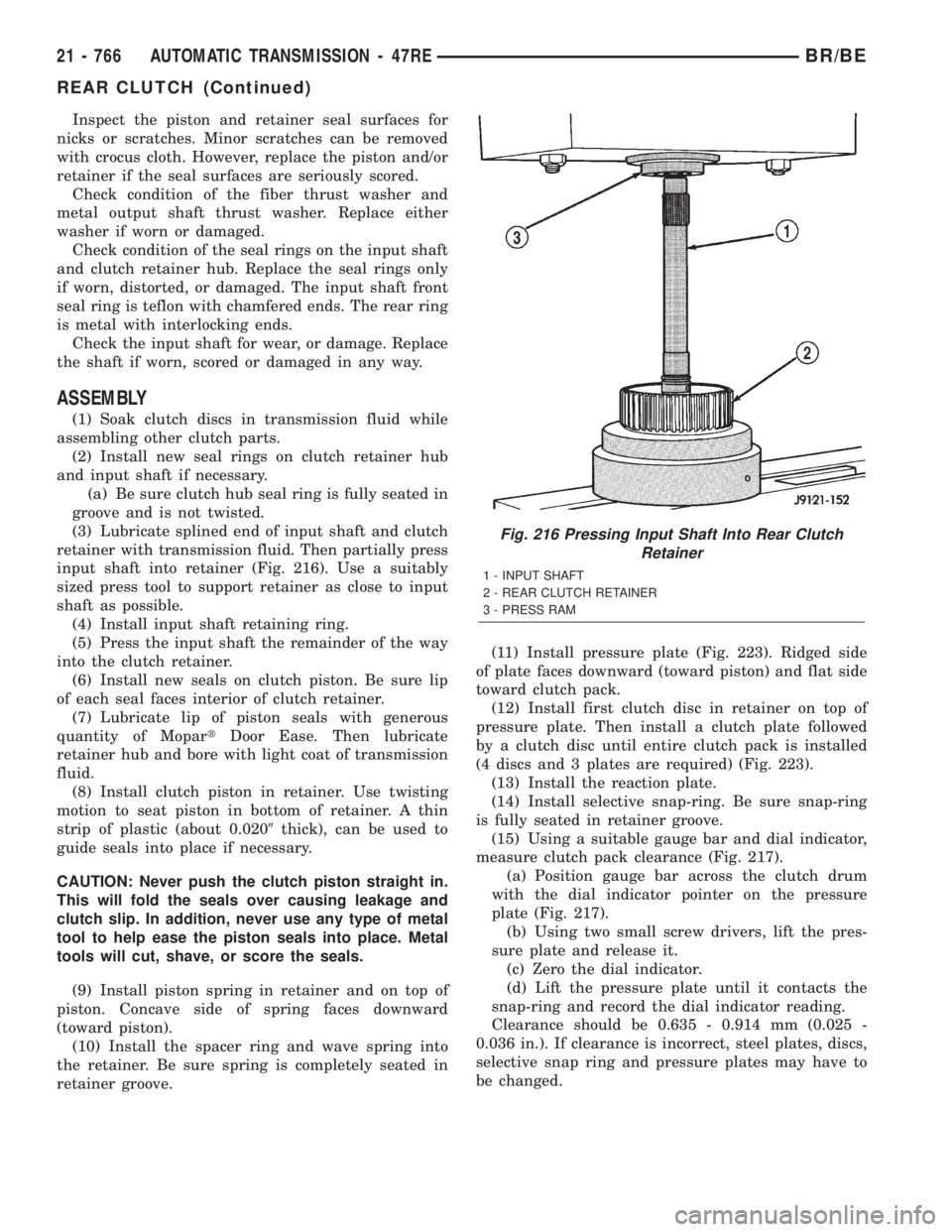
input shaft into retainer (Fig. 216). Use a suitably
sized press tool to support retainer as close to input
shaft as possible.
(4) Install input shaft retaining ring.
(5) Press the input shaft the remainder of the way
into the clutch retainer.
(6) Install new seals on clutch piston. Be sure lip
of each seal faces interior of clutch retainer.
(7) Lubricate lip of piston seals with generous
quantity of MopartDoor Ease. Then lubricate
retainer hub and bore with light coat of transmission
fluid.
(8) Install clutch piston in retainer. Use twisting
motion to seat piston in bottom of retainer. A thin
strip of plastic (about 0.0209thick), can be used to
guide seals into place if necessary.
CAUTION: Never push the clutch piston straight in.
This will fold the seals over causing leakage and
clutch slip. In addition, never use any type of metal
tool to help ease the piston seals into place. Metal
tools will cut, shave, or score the seals.
(9) Install piston spring in retainer and on top of
piston. Concave side of spring faces downward
(toward piston).
(10) Install the spacer ring and wave spring into
the retainer. Be sure spring is completely seated in
retainer groove.(11) Install pressure plate (Fig. 223). Ridged side
of plate faces downward (toward piston) and flat side
toward clutch pack.
(12) Install first clutch disc in retainer on top of
pressure plate. Then install a clutch plate followed
by a clutch disc until entire clutch pack is installed
(4 discs and 3 plates are required) (Fig. 223).
(13) Install the reaction plate.
(14) Install selective snap-ring. Be sure snap-ring
is fully seated in retainer groove.
(15) Using a suitable gauge bar and dial indicator,
measure clutch pack clearance (Fig. 217).
(a) Position gauge bar across the clutch drum
with the dial indicator pointer on the pressure
plate (Fig. 217).
(b) Using two small screw drivers, lift the pres-
sure plate and release it.
(c) Zero the dial indicator.
(d) Lift the pressure plate until it contacts the
snap-ring and record the dial indicator reading.
Clearance should be 0.635 - 0.914 mm (0.025 -
0.036 in.). If clearance is incorrect, steel plates, discs,
selective snap ring and pressure plates may have to
be changed.
Fig. 216 Pressing Input Shaft Into Rear Clutch
Retainer
1 - INPUT SHAFT
2 - REAR CLUTCH RETAINER
3 - PRESS RAM
21 - 766 AUTOMATIC TRANSMISSION - 47REBR/BE
REAR CLUTCH (Continued)