2001 DODGE RAM interior
[x] Cancel search: interiorPage 720 of 2889
VEHICLE THEFT SECURITY
TABLE OF CONTENTS
page page
VEHICLE THEFT SECURITY
DESCRIPTION............................1
OPERATION.............................2
DIAGNOSIS AND TESTING..................3
VEHICLE THEFT SECURITY SYSTEM........3VTSS INDICATOR
DESCRIPTION............................3
OPERATION.............................3
DIAGNOSIS AND TESTING..................3
VTSS INDICATOR.......................3
VEHICLE THEFT SECURITY
DESCRIPTION
The Vehicle Theft Security System (VTSS) is an
available factory-installed option on this model when
it is also equipped with the high-line or premium
Central Timer Module (CTM). The VTSS is designed
to provide perimeter protection against unauthorized
use or tampering by monitoring the vehicle doors and
the ignition system. If unauthorized vehicle use or
tampering is detected, the system responds by puls-
ing the horn, flashing the headlamps, and preventing
the engine from operating.
The VTSS includes the following major compo-
nents, which are described in further detail else-
where in this service manual:
²Central Timer Module- The high-line or pre-
mium Central Timer Module (CTM) is located under
the driver side end of the instrument panel, inboard
of the instrument panel steering column opening.
The high-line or premium CTM contains a micropro-
cessor and software that allow it to provide many
electronic functions and features not available with
base version of the CTM, including the VTSS. The
CTM provides all of the proper VTSS features and
outputs based upon the monitored inputs. The CTM
circuitry monitors hard wired switch inputs, as well
as message inputs received from other vehicle elec-
tronic modules over the Chrysler Collision Detection
(CCD) data bus network. (Refer to 8 - ELECTRICAL/
ELECTRONIC CONTROL MODULES/BODY CON-
TROL/CENTRAL TIMER MODULE -
DESCRIPTION).
²Door Ajar Switch- A door ajar switch is
located on the hinge pillar of each front door in the
vehicle. These switches provide an input to the VTSS
indicating whether the door is opened or closed.
(Refer to 8 - ELECTRICAL/LAMPS/LIGHTING -
INTERIOR/DOOR AJAR SWITCH - DESCRIPTION).
²Door Cylinder Lock Switch- A door cylinder
lock switch is located on the back of each front door
lock cylinder. This switch provides an input to theVTSS indicating whether the system should remain
armed or be disarmed. (Refer to 8 - ELECTRICAL/
POWER LOCKS/DOOR CYLINDER LOCK SWITCH
- DESCRIPTION).
²Horn Relay- The horn relay is located in the
Power Distribution Center (PDC) in the engine com-
partment near the battery. The horn relay is nor-
mally activated by the horn switch to control the
sounding of the vehicle horn or horns. However, it
can also be activated by an output of the Central
Timer Module (CTM) to provide an audible indication
that unauthorized vehicle use or tampering has been
detected. (Refer to 8 - ELECTRICAL/HORN/HORN
RELAY - DESCRIPTION).
²Headlamp Relay- The headlamp relay (also
known as the security relay) is located in the Power
Distribution Center (PDC) in the engine compart-
ment near the battery. The headlamp relay is nor-
mally activated by the Central Timer Module (CTM)
based upon inputs from the Remote Keyless Entry
(RKE) panic mode feature. However, it can also be
activated by an output of the CTM to flash the head-
lamp low beams to provide a highly visible indication
that unauthorized vehicle use or tampering has been
detected. (Refer to 8 - ELECTRICAL/LAMPS/LIGHT-
ING - EXTERIOR/HEADLAMP RELAY - DESCRIP-
TION).
²VTSS Indicator- A red Light Emitting Diode
(LED) located on the lower surface of the overhead
console near the windshield is illuminated by an out-
put of the Central Timer Module (CTM) to indicate
the status of the VTSS. This LED is integral to the
electronic circuit board for the Compass Mini-Trip
Computer (CMTC). (Refer to 8 - ELECTRICAL/
OVERHEAD CONSOLE/COMPASS/MINI-TRIP
COMPUTER - DESCRIPTION).
The engine no-run feature of the VTSS relies upon
communication between the high-line or premium
CTM and the Powertrain Control Module (PCM) over
the Chrysler Collision Detection (CCD) data bus net-
work.
Hard wired circuitry connects many of the VTSS
components to each other through the electrical sys-
BR/BEVEHICLE THEFT SECURITY 8Q - 1
Page 742 of 2889
WIRING
TABLE OF CONTENTS
page page
WIRING DIAGRAM INFORMATION....... 8W-01-1
COMPONENT INDEX.................. 8W-02-1
POWER DISTRIBUTION............... 8W-10-1
JUNCTION BLOCK.................... 8W-12-1
GROUND DISTRIBUTION.............. 8W-15-1
BUS COMMUNICATIONS.............. 8W-18-1
CHARGING SYSTEM.................. 8W-20-1
STARTING SYSTEM.................. 8W-21-1
FUEL/IGNITION SYSTEM.............. 8W-30-1
TRANSMISSION CONTROL SYSTEM..... 8W-31-1
VEHICLE SPEED CONTROL............ 8W-33-1
REAR WHEEL ANTILOCK BRAKES....... 8W-34-1
ALL WHEEL ANTILOCK BRAKES........ 8W-35-1
VEHICLE THEFT SECURITY SYSTEM..... 8W-39-1
INSTRUMENT CLUSTER............... 8W-40-1
HORN/CIGAR LIGHTER/POWER OUTLET . . 8W-41-1
AIR CONDITIONING-HEATER........... 8W-42-1
AIRBAG SYSTEM.................... 8W-43-1INTERIOR LIGHTING.................. 8W-44-1
CENTRAL TIMER MODULE............. 8W-45-1
AUDIO SYSTEM..................... 8W-47-1
OVERHEAD CONSOLE................. 8W-49-1
FRONT LIGHTING.................... 8W-50-1
REAR LIGHTING..................... 8W-51-1
TURN SIGNALS...................... 8W-52-1
WIPERS............................ 8W-53-1
TRAILER TOW....................... 8W-54-1
POWER WINDOWS................... 8W-60-1
POWER DOOR LOCKS................ 8W-61-1
POWER MIRRORS................... 8W-62-1
POWER SEATS...................... 8W-63-1
SPLICE INFORMATION................ 8W-70-1
CONNECTOR PIN-OUTS............... 8W-80-1
CONNECTOR/GROUND LOCATIONS...... 8W-90-1
SPLICE LOCATIONS.................. 8W-95-1
POWER DISTRIBUTION............... 8W-97-1 BR/BEWIRING 8W - 1
Page 924 of 2889
8W-44 INTERIOR LIGHTING
Component Page
Ash Receiver Lamp................... 8W-44-6
Cargo Lamp No. 1.................... 8W-44-4
Cargo Lamp No. 2.................... 8W-44-4
Central Timer Module C1.............. 8W-44-5
Cup Holder Lamp.................... 8W-44-6
Data Link Connector................. 8W-44-2
Dome Lamp........................ 8W-44-4
Fuse 5 (JB)......................... 8W-44-6
Fuse 11 (JB)........................ 8W-44-5
Fuse 12 (JB)...................... 8W-44-2, 3
G100.............................. 8W-44-2
G200.............................. 8W-44-3
G201.......................... 8W-44-2, 4, 6
Glove Box Lamp And Switch............ 8W-44-2Component Page
Headlamp Switch................ 8W-44-4, 5, 6
Ignition Switch...................... 8W-44-5
Joint Connector No. 4................. 8W-44-2
Joint Connector No. 5............... 8W-44-2, 6
Joint Connector No. 6................. 8W-44-5
Joint Connector No. 8............. 8W-44-4, 5, 6
Junction Block............... 8W-44-2, 3, 4, 5, 6
Left Visor/Vanity Lamp................ 8W-44-2
Overhead Console.................... 8W-44-3
Power Mirror Switch.................. 8W-44-4
Radio............................ 8W-44-2, 6
Right Visor/Vanity Lamp............... 8W-44-2
Underhood Lamp.................... 8W-44-2
BR/BE8W-44 INTERIOR LIGHTING 8W - 44 - 1
Page 1509 of 2889
(7) Connect two mounting straps and mounting
strap nuts.
(8) Tighten strap nuts to 41 N´m (30 ft. lbs.)
torque. Do not over tighten retaining strap nuts.
(9) Remove transmission jack.
(10) Connect fuel filler tube assembly to body.
(11) If equipped, connect grounding wire (strap)
and screw.
(12) Refill fuel tank and inspect all hoses and lines
for leaks.
(13)
Connect negative battery cable(s) to battery(s).
INLET FILTER
REMOVAL
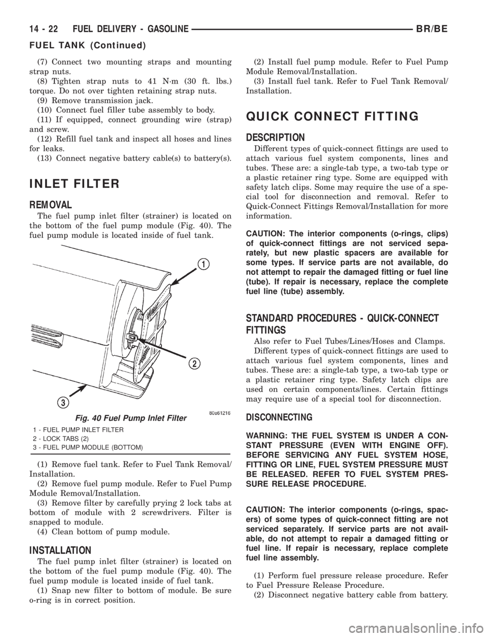
The fuel pump inlet filter (strainer) is located on
the bottom of the fuel pump module (Fig. 40). The
fuel pump module is located inside of fuel tank.
(1) Remove fuel tank. Refer to Fuel Tank Removal/
Installation.
(2) Remove fuel pump module. Refer to Fuel Pump
Module Removal/Installation.
(3) Remove filter by carefully prying 2 lock tabs at
bottom of module with 2 screwdrivers. Filter is
snapped to module.
(4) Clean bottom of pump module.
INSTALLATION
The fuel pump inlet filter (strainer) is located on
the bottom of the fuel pump module (Fig. 40). The
fuel pump module is located inside of fuel tank.
(1) Snap new filter to bottom of module. Be sure
o-ring is in correct position.(2) Install fuel pump module. Refer to Fuel Pump
Module Removal/Installation.
(3) Install fuel tank. Refer to Fuel Tank Removal/
Installation.
QUICK CONNECT FITTING
DESCRIPTION
Different types of quick-connect fittings are used to
attach various fuel system components, lines and
tubes. These are: a single-tab type, a two-tab type or
a plastic retainer ring type. Some are equipped with
safety latch clips. Some may require the use of a spe-
cial tool for disconnection and removal. Refer to
Quick-Connect Fittings Removal/Installation for more
information.
CAUTION: The interior components (o-rings, clips)
of quick-connect fittings are not serviced sepa-
rately, but new plastic spacers are available for
some types. If service parts are not available, do
not attempt to repair the damaged fitting or fuel line
(tube). If repair is necessary, replace the complete
fuel line (tube) assembly.
STANDARD PROCEDURES - QUICK-CONNECT
FITTINGS
Also refer to Fuel Tubes/Lines/Hoses and Clamps.
Different types of quick-connect fittings are used to
attach various fuel system components, lines and
tubes. These are: a single-tab type, a two-tab type or
a plastic retainer ring type. Safety latch clips are
used on certain components/lines. Certain fittings
may require use of a special tool for disconnection.
DISCONNECTING
WARNING: THE FUEL SYSTEM IS UNDER A CON-
STANT PRESSURE (EVEN WITH ENGINE OFF).
BEFORE SERVICING ANY FUEL SYSTEM HOSE,
FITTING OR LINE, FUEL SYSTEM PRESSURE MUST
BE RELEASED. REFER TO FUEL SYSTEM PRES-
SURE RELEASE PROCEDURE.
CAUTION: The interior components (o-rings, spac-
ers) of some types of quick-connect fitting are not
serviced separately. If service parts are not avail-
able, do not attempt to repair a damaged fitting or
fuel line. If repair is necessary, replace complete
fuel line assembly.
(1) Perform fuel pressure release procedure. Refer
to Fuel Pressure Release Procedure.
(2) Disconnect negative battery cable from battery.
Fig. 40 Fuel Pump Inlet Filter
1 - FUEL PUMP INLET FILTER
2 - LOCK TABS (2)
3 - FUEL PUMP MODULE (BOTTOM)
14 - 22 FUEL DELIVERY - GASOLINEBR/BE
FUEL TANK (Continued)
Page 1674 of 2889
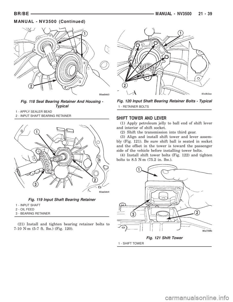
(21) Install and tighten bearing retainer bolts to
7-10 N´m (5-7 ft. lbs.) (Fig. 120).
SHIFT TOWER AND LEVER
(1) Apply petroleum jelly to ball end of shift lever
and interior of shift socket.
(2) Shift the transmission into third gear.
(3) Align and install shift tower and lever assem-
bly (Fig. 121). Be sure shift ball is seated in socket
and the offset in the tower is toward the passenger
side of the vehicle before installing tower bolts.
(4) Install shift tower bolts (Fig. 122) and tighten
bolts to 8.5 N´m (75.2 in. lbs.).
Fig. 118 Seal Bearing Retainer And Housing -
Typical
1 - APPLY SEALER BEAD
2 - INPUT SHAFT BEARING RETAINER
Fig. 119 Input Shaft Bearing Retainer
1 - INPUT SHAFT
2 - OIL FEED
3 - BEARING RETAINER
Fig. 120 Input Shaft Bearing Retainer Bolts - Typical
1 - RETAINER BOLTS
Fig. 121 Shift Tower
1 - SHIFT TOWER
BR/BEMANUAL - NV3500 21 - 39
MANUAL - NV3500 (Continued)
Page 1841 of 2889
ASSEMBLY
NOTE: The 42RE transmission uses four plates and
discs for the front clutch.
(1) Soak clutch discs in transmission fluid while
assembling other clutch parts.
(2) Install new seals in the clutch retainer lower
groove and on outer diameter of the retainer hub. Be
sure lip of each seal faces interior of clutch retainer.
(3) Lubricate lips of the retainer seals with liberal
quantity of MopartDoor Ease. Then lubricate
retainer hub, bore and piston with light coat of trans-
mission fluid.
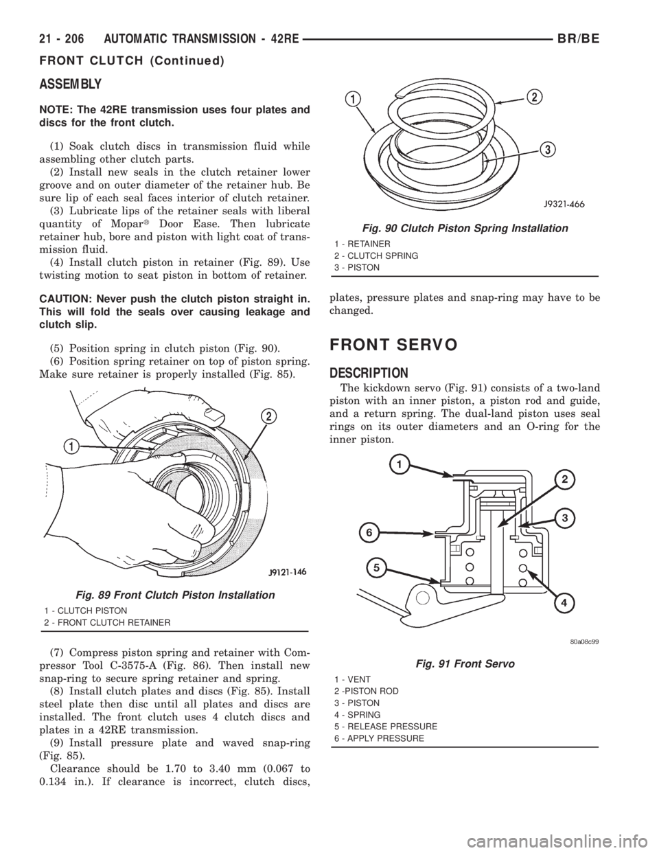
(4) Install clutch piston in retainer (Fig. 89). Use
twisting motion to seat piston in bottom of retainer.
CAUTION: Never push the clutch piston straight in.
This will fold the seals over causing leakage and
clutch slip.
(5) Position spring in clutch piston (Fig. 90).
(6) Position spring retainer on top of piston spring.
Make sure retainer is properly installed (Fig. 85).
(7) Compress piston spring and retainer with Com-
pressor Tool C-3575-A (Fig. 86). Then install new
snap-ring to secure spring retainer and spring.
(8) Install clutch plates and discs (Fig. 85). Install
steel plate then disc until all plates and discs are
installed. The front clutch uses 4 clutch discs and
plates in a 42RE transmission.
(9) Install pressure plate and waved snap-ring
(Fig. 85).
Clearance should be 1.70 to 3.40 mm (0.067 to
0.134 in.). If clearance is incorrect, clutch discs,plates, pressure plates and snap-ring may have to be
changed.
FRONT SERVO
DESCRIPTION
The kickdown servo (Fig. 91) consists of a two-land
piston with an inner piston, a piston rod and guide,
and a return spring. The dual-land piston uses seal
rings on its outer diameters and an O-ring for the
inner piston.
Fig. 89 Front Clutch Piston Installation
1 - CLUTCH PISTON
2 - FRONT CLUTCH RETAINER
Fig. 90 Clutch Piston Spring Installation
1 - RETAINER
2 - CLUTCH SPRING
3 - PISTON
Fig. 91 Front Servo
1 - VENT
2 -PISTON ROD
3 - PISTON
4 - SPRING
5 - RELEASE PRESSURE
6 - APPLY PRESSURE
21 - 206 AUTOMATIC TRANSMISSION - 42REBR/BE
FRONT CLUTCH (Continued)
Page 1883 of 2889

materials will adhere to component surfaces and
could restrict or block fluid passages after assembly.
INSPECTION
Replace the clutch discs if warped, worn, scored,
burned/charred, the lugs are damaged, or if the fac-
ing is flaking off. Replace the top and bottom pres-
sure plates if scored, warped, or cracked. Be sure the
driving lugs on the pressure and clutch plates are
also in good condition. The lugs must not be bent,
cracked or damaged in any way.
Replace the piston spring and wave spring if either
part is distorted, warped or broken.
Check the lug grooves in the clutch retainer. The
clutch and pressure plates should slide freely in the
slots. Replace the retainer if the grooves are worn or
damaged. Also check action of the check balls in the
retainer and piston. Each check ball must move
freely and not stick.
Replace the retainer bushing if worn, scored, or
doubt exists about bushing condition.
Inspect the piston and retainer seal surfaces for
nicks or scratches. Minor scratches can be removed
with crocus cloth. However, replace the piston and/or
retainer if the seal surfaces are seriously scored.
Check condition of the fiber thrust washer and
metal output shaft thrust washer. Replace either
washer if worn or damaged.
Check condition of the seal rings on the input shaft
and clutch retainer hub. Replace the seal rings only
if worn, distorted, or damaged. The input shaft front
seal ring is teflon with chamfered ends. The rear ring
is metal with interlocking ends.
Check the input shaft for wear, or damage. Replace
the shaft if worn, scored or damaged in any way.
ASSEMBLY
(1) Soak clutch discs in transmission fluid while
assembling other clutch parts.
(2) Install new seal rings on clutch retainer hub
and input shaft, if necessary, (Fig. 218) and (Fig.
219).
(a) Be sure clutch hub seal ring is fully seated in
groove and is not twisted.
(3) Lubricate splined end of input shaft and clutch
retainer with transmission fluid. Then press input
shaft into retainer (Fig. 220). Use a suitably sized
press tool to support retainer as close to input shaft
as possible.
(4) Install input shaft snap-ring (Fig. 217).
(5) Invert retainer and press input shaft in oppo-
site direction until snap-ring is seated.
(6) Install new seals on clutch piston. Be sure lip
of each seal faces interior of clutch retainer.
(7) Lubricate lip of piston seals with generous
quantity of MopartDoor Ease. Then lubricate
retainer hub and bore with light coat of transmission
fluid.
(8) Install clutch piston in retainer. Use twisting
motion to seat piston in bottom of retainer. A thin
strip of plastic (about 0.0209thick), can be used to
guide seals into place if necessary.
CAUTION: Never push the clutch piston straight in.
This will fold the seals over causing leakage and
clutch slip. In addition, never use any type of metal
tool to help ease the piston seals into place. Metal
tools will cut, shave, or score the seals.
(9) Install piston spring in retainer and on top of
piston (Fig. 221). Concave side of spring faces down-
ward (toward piston).
(10) Install wave spring in retainer (Fig. 221). Be
sure spring is completely seated in retainer groove.
(11) Install bottom pressure plate (Fig. 216).
Ridged side of plate faces downward (toward piston)
and flat side toward clutch pack.
(12) Install first clutch disc in retainer on top of
bottom pressure plate. Then install a clutch plate fol-
lowed by a clutch disc until entire clutch pack is
installed (4 discs and 3 plates are required) (Fig.
216).
(13) Install top pressure plate.
(14) Install selective snap-ring. Be sure snap-ring
is fully seated in retainer groove.
Fig. 217 Removing Input Shaft Snap-Ring
1 - REAR CLUTCH RETAINER
2 - INPUT SHAFT SNAP-RING
3 - SNAP-RING PLIERS
21 - 248 AUTOMATIC TRANSMISSION - 42REBR/BE
REAR CLUTCH (Continued)
Page 1928 of 2889
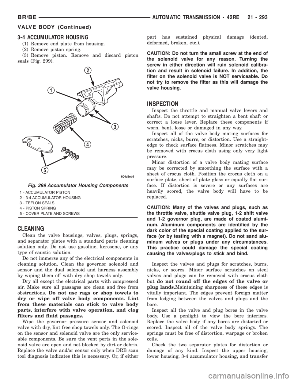
3-4 ACCUMULATOR HOUSING
(1) Remove end plate from housing.
(2) Remove piston spring.
(3) Remove piston. Remove and discard piston
seals (Fig. 299).
CLEANING
Clean the valve housings, valves, plugs, springs,
and separator plates with a standard parts cleaning
solution only. Do not use gasoline, kerosene, or any
type of caustic solution.
Do not immerse any of the electrical components in
cleaning solution. Clean the governor solenoid and
sensor and the dual solenoid and harness assembly
by wiping them off with dry shop towels only.
Dry all except the electrical parts with compressed
air. Make sure all passages are clean and free from
obstructions.Do not use rags or shop towels to
dry or wipe off valve body components. Lint
from these materials can stick to valve body
parts, interfere with valve operation, and clog
filters and fluid passages.
Wipe the governor pressure sensor and solenoid
valve with dry, lint free shop towels only. The O-rings
on the sensor and solenoid valve are the only service-
able components. Be sure the vent ports in the sole-
noid valve are open and not blocked by dirt or debris.
Replace the valve and/or sensor only when DRB scan
tool diagnosis indicates this is necessary. Or, if eitherpart has sustained physical damage (dented,
deformed, broken, etc.).
CAUTION: Do not turn the small screw at the end of
the solenoid valve for any reason. Turning the
screw in either direction will ruin solenoid calibra-
tion and result in solenoid failure. In addition, the
filter on the solenoid valve is NOT serviceable. Do
not try to remove the filter as this will damage the
valve housing.
INSPECTION
Inspect the throttle and manual valve levers and
shafts. Do not attempt to straighten a bent shaft or
correct a loose lever. Replace these components if
worn, bent, loose or damaged in any way.
Inspect all of the valve body mating surfaces for
scratches, nicks, burrs, or distortion. Use a straight-
edge to check surface flatness. Minor scratches may
be removed with crocus cloth using only very light
pressure.
Minor distortion of a valve body mating surface
may be corrected by smoothing the surface with a
sheet of crocus cloth. Position the crocus cloth on a
surface plate, sheet of plate glass or equally flat sur-
face. If distortion is severe or any surfaces are
heavily scored, the valve body will have to be
replaced.
CAUTION: Many of the valves and plugs, such as
the throttle valve, shuttle valve plug, 1-2 shift valve
and 1-2 governor plug, are made of coated alumi-
num. Aluminum components are identified by the
dark color of the special coating applied to the sur-
face (or by testing with a magnet). Do not sand alu-
minum valves or plugs under any circumstances.
This practice could damage the special coating
causing the valves/plugs to stick and bind.
Inspect the valves and plugs for scratches, burrs,
nicks, or scores. Minor surface scratches on steel
valves and plugs can be removed with crocus cloth
butdo not round off the edges of the valve or
plug lands.Maintaining sharpness of these edges is
vitally important. The edges prevent foreign matter
from lodging between the valves and plugs and the
bore.
Inspect all the valve and plug bores in the valve
body. Use a penlight to view the bore interiors.
Replace the valve body if any bores are distorted or
scored. Inspect all of the valve body springs. The
springs must be free of distortion, warpage or broken
coils.
Check the two separator plates for distortion or
damage of any kind. Inspect the upper housing,
lower housing, 3-4 accumulator housing, and transfer
Fig. 299 Accumulator Housing Components
1 - ACCUMULATOR PISTON
2 - 3-4 ACCUMULATOR HOUSING
3 - TEFLON SEALS
4 - PISTON SPRING
5 - COVER PLATE AND SCREWS
BR/BEAUTOMATIC TRANSMISSION - 42RE 21 - 293
VALVE BODY (Continued)