2001 DODGE RAM drain bolt
[x] Cancel search: drain boltPage 89 of 2889
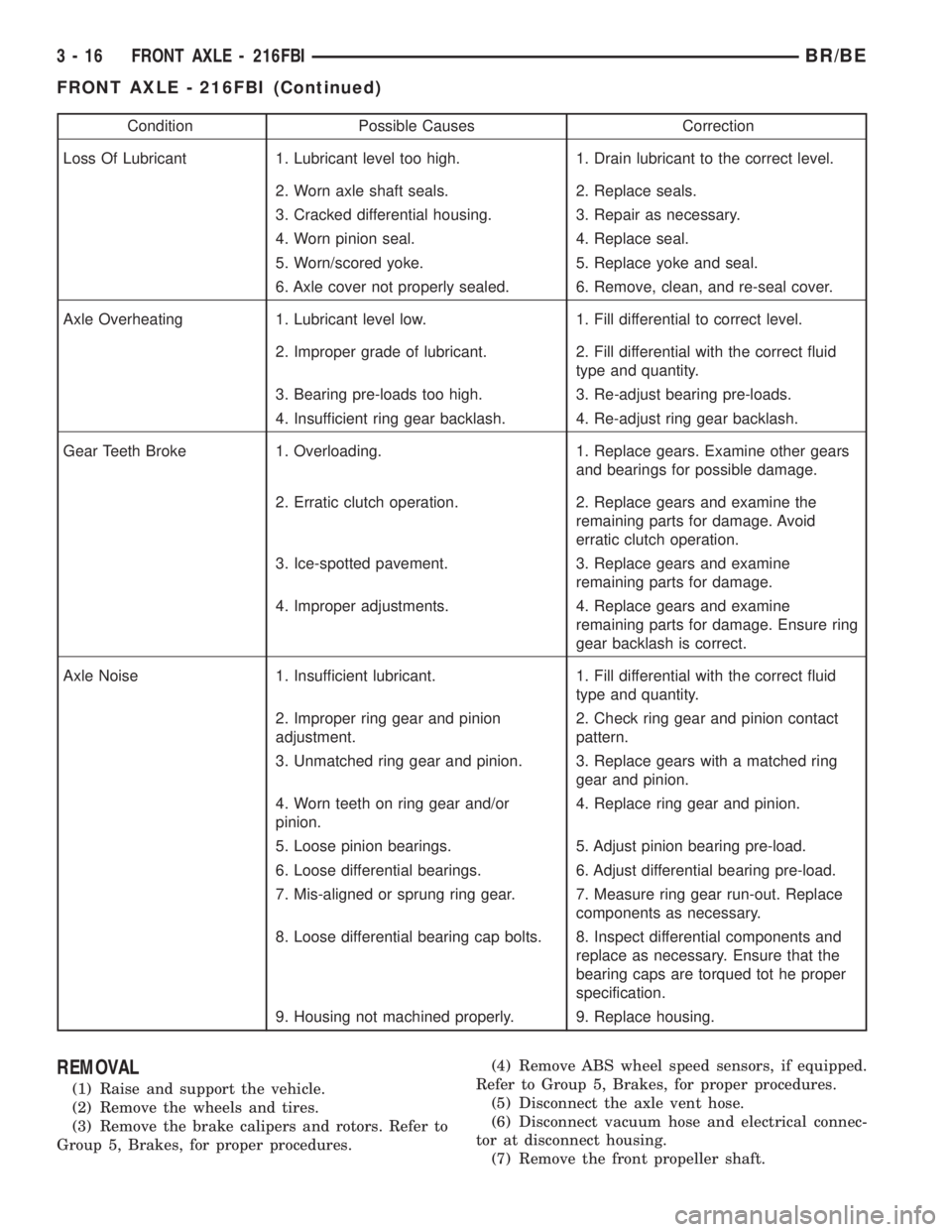
Condition Possible Causes Correction
Loss Of Lubricant 1. Lubricant level too high. 1. Drain lubricant to the correct level.
2. Worn axle shaft seals. 2. Replace seals.
3. Cracked differential housing. 3. Repair as necessary.
4. Worn pinion seal. 4. Replace seal.
5. Worn/scored yoke. 5. Replace yoke and seal.
6. Axle cover not properly sealed. 6. Remove, clean, and re-seal cover.
Axle Overheating 1. Lubricant level low. 1. Fill differential to correct level.
2. Improper grade of lubricant. 2. Fill differential with the correct fluid
type and quantity.
3. Bearing pre-loads too high. 3. Re-adjust bearing pre-loads.
4. Insufficient ring gear backlash. 4. Re-adjust ring gear backlash.
Gear Teeth Broke 1. Overloading. 1. Replace gears. Examine other gears
and bearings for possible damage.
2. Erratic clutch operation. 2. Replace gears and examine the
remaining parts for damage. Avoid
erratic clutch operation.
3. Ice-spotted pavement. 3. Replace gears and examine
remaining parts for damage.
4. Improper adjustments. 4. Replace gears and examine
remaining parts for damage. Ensure ring
gear backlash is correct.
Axle Noise 1. Insufficient lubricant. 1. Fill differential with the correct fluid
type and quantity.
2. Improper ring gear and pinion
adjustment.2. Check ring gear and pinion contact
pattern.
3. Unmatched ring gear and pinion. 3. Replace gears with a matched ring
gear and pinion.
4. Worn teeth on ring gear and/or
pinion.4. Replace ring gear and pinion.
5. Loose pinion bearings. 5. Adjust pinion bearing pre-load.
6. Loose differential bearings. 6. Adjust differential bearing pre-load.
7. Mis-aligned or sprung ring gear. 7. Measure ring gear run-out. Replace
components as necessary.
8. Loose differential bearing cap bolts. 8. Inspect differential components and
replace as necessary. Ensure that the
bearing caps are torqued tot he proper
specification.
9. Housing not machined properly. 9. Replace housing.
REMOVAL
(1) Raise and support the vehicle.
(2) Remove the wheels and tires.
(3) Remove the brake calipers and rotors. Refer to
Group 5, Brakes, for proper procedures.(4) Remove ABS wheel speed sensors, if equipped.
Refer to Group 5, Brakes, for proper procedures.
(5) Disconnect the axle vent hose.
(6) Disconnect vacuum hose and electrical connec-
tor at disconnect housing.
(7) Remove the front propeller shaft.
3 - 16 FRONT AXLE - 216FBIBR/BE
FRONT AXLE - 216FBI (Continued)
Page 122 of 2889
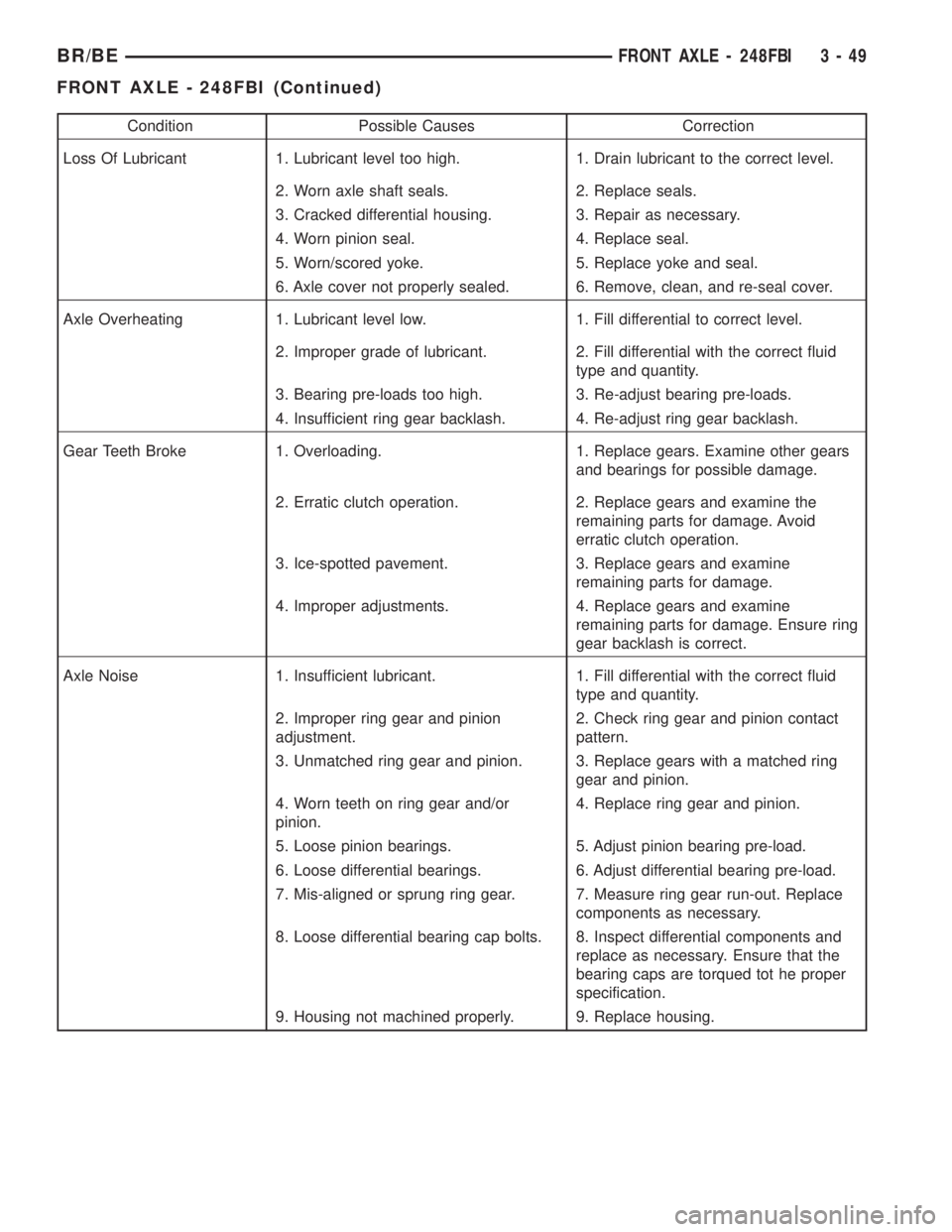
Condition Possible Causes Correction
Loss Of Lubricant 1. Lubricant level too high. 1. Drain lubricant to the correct level.
2. Worn axle shaft seals. 2. Replace seals.
3. Cracked differential housing. 3. Repair as necessary.
4. Worn pinion seal. 4. Replace seal.
5. Worn/scored yoke. 5. Replace yoke and seal.
6. Axle cover not properly sealed. 6. Remove, clean, and re-seal cover.
Axle Overheating 1. Lubricant level low. 1. Fill differential to correct level.
2. Improper grade of lubricant. 2. Fill differential with the correct fluid
type and quantity.
3. Bearing pre-loads too high. 3. Re-adjust bearing pre-loads.
4. Insufficient ring gear backlash. 4. Re-adjust ring gear backlash.
Gear Teeth Broke 1. Overloading. 1. Replace gears. Examine other gears
and bearings for possible damage.
2. Erratic clutch operation. 2. Replace gears and examine the
remaining parts for damage. Avoid
erratic clutch operation.
3. Ice-spotted pavement. 3. Replace gears and examine
remaining parts for damage.
4. Improper adjustments. 4. Replace gears and examine
remaining parts for damage. Ensure ring
gear backlash is correct.
Axle Noise 1. Insufficient lubricant. 1. Fill differential with the correct fluid
type and quantity.
2. Improper ring gear and pinion
adjustment.2. Check ring gear and pinion contact
pattern.
3. Unmatched ring gear and pinion. 3. Replace gears with a matched ring
gear and pinion.
4. Worn teeth on ring gear and/or
pinion.4. Replace ring gear and pinion.
5. Loose pinion bearings. 5. Adjust pinion bearing pre-load.
6. Loose differential bearings. 6. Adjust differential bearing pre-load.
7. Mis-aligned or sprung ring gear. 7. Measure ring gear run-out. Replace
components as necessary.
8. Loose differential bearing cap bolts. 8. Inspect differential components and
replace as necessary. Ensure that the
bearing caps are torqued tot he proper
specification.
9. Housing not machined properly. 9. Replace housing.
BR/BEFRONT AXLE - 248FBI 3 - 49
FRONT AXLE - 248FBI (Continued)
Page 169 of 2889

CAUTION: Never loosen pinion nut to decrease pin-
ion bearing rotating torque and never exceed spec-
ified preload torque. If rotating torque is exceeded,
a new collapsible spacer must be installed.(10) If the rotating torque is low, use Holder 6719
to hold the companion flange (Fig. 23) and tighten
the pinion nut in 6.8 N´m (5 ft. lbs.) increments until
proper rotating torque is achieved.
NOTE: The bearing rotating torque should be con-
stant during a complete revolution of the pinion. If
the rotating torque varies, this indicates a binding
condition.
(11) The seal replacement is unacceptable if the
final pinion nut torque is less than 285 N´m (210 ft.
lbs.).
(12) Install the propeller shaft with the installa-
tion reference marks aligned.
(13) Tighten the companion flange bolts to 108
N´m (80 ft. lbs.).
(14) Install the brake drums.
(15) Install wheel and tire assemblies and lower
the vehicle.
(16) Check the differential housing lubricant level.
DIFFERENTIAL
REMOVAL
(1) Raise and support the vehicle.
(2) Remove lubricant fill hole plug from the differ-
ential housing cover.
(3) Remove differential housing cover and drain
the lubricant from the housing.
(4) Clean the housing cavity with a flushing oil,
light engine oil or lint free cloth.Do not use water,
steam, kerosene or gasoline for cleaning.
(5) Remove the axle shafts.
(6) Remove RWAL/ABS sensor from housing.
NOTE: Side play resulting from bearing races being
loose on case hubs requires replacement of the dif-
ferential case.
(7) Mark the differential housing and differential
bearing caps for installation reference (Fig. 25).
(8) Remove bearing threaded adjuster lock from
each bearing cap. Loosen the bolts, but do not
remove the bearing caps.
(9) Loosen the threaded adjusters with Wrench
C-4164 (Fig. 26).
(10) Hold the differential case while removing
bearing caps and adjusters.
(11) Remove the differential case.
NOTE: Each differential bearing cup and threaded
adjuster must be kept with their respective bearing.
Fig. 23 Pinion Nut
1 - DIFFERENTIAL HOUSING
2 - COMPANION FLANGE HOLDER
3 - TORQUE WRENCH
Fig. 24 Pinion Rotation Torque
1 - COMPANION FLANGE
2 - INCH POUND TORQUE WRENCH
3 - 96 REAR AXLE-91/4BR/BE
PINION SEAL (Continued)
Page 171 of 2889
ASSEMBLY
(1) Install differential side gears and thrust wash-
ers.
(2) Install differential pinion and thrust washers.
(3) Install the pinion shaft.
(4) Align the hole in the pinion shaft with the hole
in the differential case and install the pinion shaft
lock screw.
(5) Lubricate all differential components with
hypoid gear lubricant.
INSTALLATION
(1) Apply a coating of hypoid gear lubricant to the
differential bearings, bearing cups, and threaded
adjusters. A dab of grease can be used to keep the
adjusters in position. Carefully position the assem-
bled differential case in the housing.
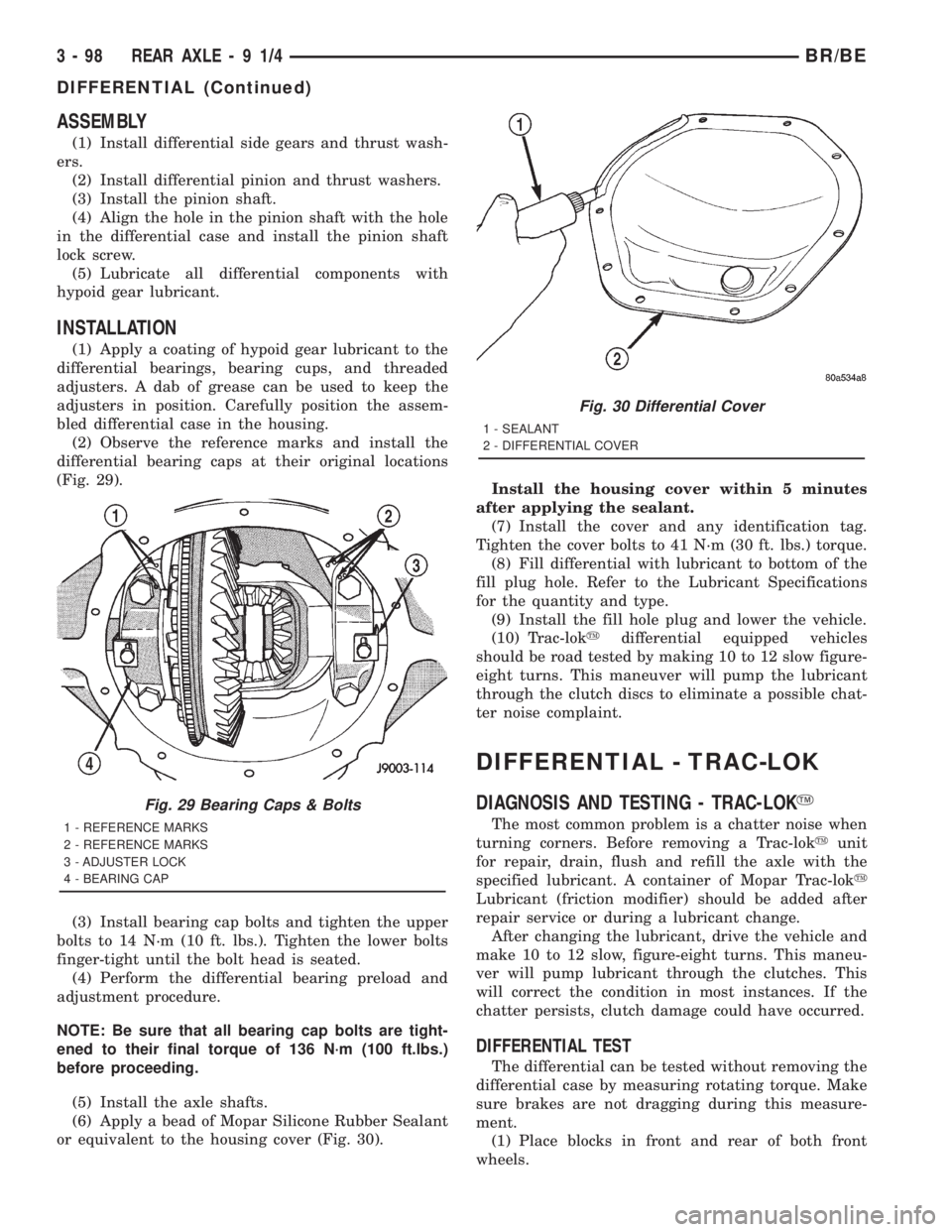
(2) Observe the reference marks and install the
differential bearing caps at their original locations
(Fig. 29).
(3) Install bearing cap bolts and tighten the upper
bolts to 14 N´m (10 ft. lbs.). Tighten the lower bolts
finger-tight until the bolt head is seated.
(4) Perform the differential bearing preload and
adjustment procedure.
NOTE: Be sure that all bearing cap bolts are tight-
ened to their final torque of 136 N´m (100 ft.lbs.)
before proceeding.
(5) Install the axle shafts.
(6) Apply a bead of Mopar Silicone Rubber Sealant
or equivalent to the housing cover (Fig. 30).Install the housing cover within 5 minutes
after applying the sealant.
(7) Install the cover and any identification tag.
Tighten the cover bolts to 41 N´m (30 ft. lbs.) torque.
(8) Fill differential with lubricant to bottom of the
fill plug hole. Refer to the Lubricant Specifications
for the quantity and type.
(9) Install the fill hole plug and lower the vehicle.
(10) Trac-lokydifferential equipped vehicles
should be road tested by making 10 to 12 slow figure-
eight turns. This maneuver will pump the lubricant
through the clutch discs to eliminate a possible chat-
ter noise complaint.
DIFFERENTIAL - TRAC-LOK
DIAGNOSIS AND TESTING - TRAC-LOKY
The most common problem is a chatter noise when
turning corners. Before removing a Trac-lokyunit
for repair, drain, flush and refill the axle with the
specified lubricant. A container of Mopar Trac-loky
Lubricant (friction modifier) should be added after
repair service or during a lubricant change.
After changing the lubricant, drive the vehicle and
make 10 to 12 slow, figure-eight turns. This maneu-
ver will pump lubricant through the clutches. This
will correct the condition in most instances. If the
chatter persists, clutch damage could have occurred.
DIFFERENTIAL TEST
The differential can be tested without removing the
differential case by measuring rotating torque. Make
sure brakes are not dragging during this measure-
ment.
(1) Place blocks in front and rear of both front
wheels.
Fig. 29 Bearing Caps & Bolts
1 - REFERENCE MARKS
2 - REFERENCE MARKS
3 - ADJUSTER LOCK
4 - BEARING CAP
Fig. 30 Differential Cover
1 - SEALANT
2 - DIFFERENTIAL COVER
3 - 98 REAR AXLE-91/4BR/BE
DIFFERENTIAL (Continued)
Page 203 of 2889

(10) Apply a bead of Mopar Silicone Rubber Seal-
ant or equivalent to the housing cover (Fig. 34).
Install the housing cover within 5 minutes
after applying the sealant.
(11) Install the cover and any identification tag.
Tighten the cover bolts in a criss-cross pattern to 47
N´m (35 ft. lbs.).
(12) Refill the differential with Mopar Hypoid
Gear Lubricant or equivalent to bottom of the fill
plug hole. Refer to the Lubricant Specifications for
correct quantity and type.
(13) Install the fill hole plug and tighten to 34 N´m
(25 ft. lbs.).
(14) Remove support and lower vehicle.
DIFFERENTIAL - TRAC-LOK
DIAGNOSIS AND TESTING - TRAC-LOKY
The most common problem is a chatter noise when
turning corners. Before removing a Trac-lokyunit
for repair, drain, flush and refill the axle with the
specified lubricant. A container of Mopar Trac-loky
Lubricant (friction modifier) should be added after
repair service or during a lubricant change.
After changing the lubricant, drive the vehicle and
make 10 to 12 slow, figure-eight turns. This maneu-
ver will pump lubricant through the clutches. Thiswill correct the condition in most instances. If the
chatter persists, clutch damage could have occurred.
DIFFERENTIAL TEST
The differential can be tested without removing the
differential case by measuring rotating torque. Make
sure brakes are not dragging during this measure-
ment.
(1) Place blocks in front and rear of both front
wheels.
(2) Raise one rear wheel until it is completely off
the ground.
(3) Engine off, transmission in neutral, and park-
ing brake off.
(4) Remove wheel and bolt Special Tool 6790 or
equivalent tool to studs.
(5) Use torque wrench on special tool to rotate
wheel and read rotating torque (Fig. 35).
(6) If rotating torque is less than 22 N´m (30 ft.
lbs.) or more than 271 N´m (200 ft. lbs.) on either
wheel the unit should be serviced.
DISASSEMBLY
(1) Clamp side gear Holding Fixture 6965 in a vise
and position the differential case on the Holding Fix-
ture (Fig. 36).
(2) Remove ring gear if the ring gear is to be
replaced. The Trac-lokydifferential can be serviced
with the ring gear installed.
(3) Remove pinion shaft roll pin.
(4) Remove pinion shaft with a drift and hammer
(Fig. 37).
(5) Install and lubricate Step Plate C-6960-3 (Fig.
38).
Fig. 34 Differential Cover
1 - SEALANT SURFACE
2 - SEALANT
3 - SEALANT THICKNESS
Fig. 35 Trac-lokYTest -Typical
1 - SPECIAL TOOL 6790 WITH BOLT IN CENTER HOLE
2 - TORQUE WRENCH
3 - 130 REAR AXLE - 248RBIBR/BE
DIFFERENTIAL (Continued)
Page 263 of 2889
(14) Remove support and lower vehicle.
DIFFERENTIAL - TRAC-LOK
DIAGNOSIS AND TESTING - TRAC-LOKY
The most common problem is a chatter noise when
turning corners. Before removing a Trac-lokyunit
for repair, drain, flush and refill the axle with the
specified lubricant. A container of Mopar Trac-loky
Lubricant (friction modifier) should be added after
repair service or during a lubricant change.
After changing the lubricant, drive the vehicle and
make 10 to 12 slow, figure-eight turns. This maneu-
ver will pump lubricant through the clutches. This
will correct the condition in most instances. If the
chatter persists, clutch damage could have occurred.
DIFFERENTIAL TEST
The differential can be tested without removing the
differential case by measuring rotating torque. Make
sure brakes are not dragging during this measure-
ment.
(1) Place blocks in front and rear of both front
wheels.
(2) Raise one rear wheel until it is completely off
the ground.
(3) Engine off, transmission in neutral, and park-
ing brake off.(4) Remove wheel and bolt Special Tool 6790 or
equivalent tool to studs.
(5) Use torque wrench on special tool to rotate
wheel and read rotating torque (Fig. 35).
(6) If rotating torque is less than 22 N´m (30 ft.
lbs.) or more than 271 N´m (200 ft. lbs.) on either
wheel the unit should be serviced.
DISASSEMBLY
The Trac-Lokydifferential on this axle has a one-
piece cross shaft and uses one dished disc, regular 5
disc and 7 plates.
NOTE: Pay attention to the clutch pack arrangement
during disassembly. Note the direction of the con-
cave and convex side of the plates and discs.
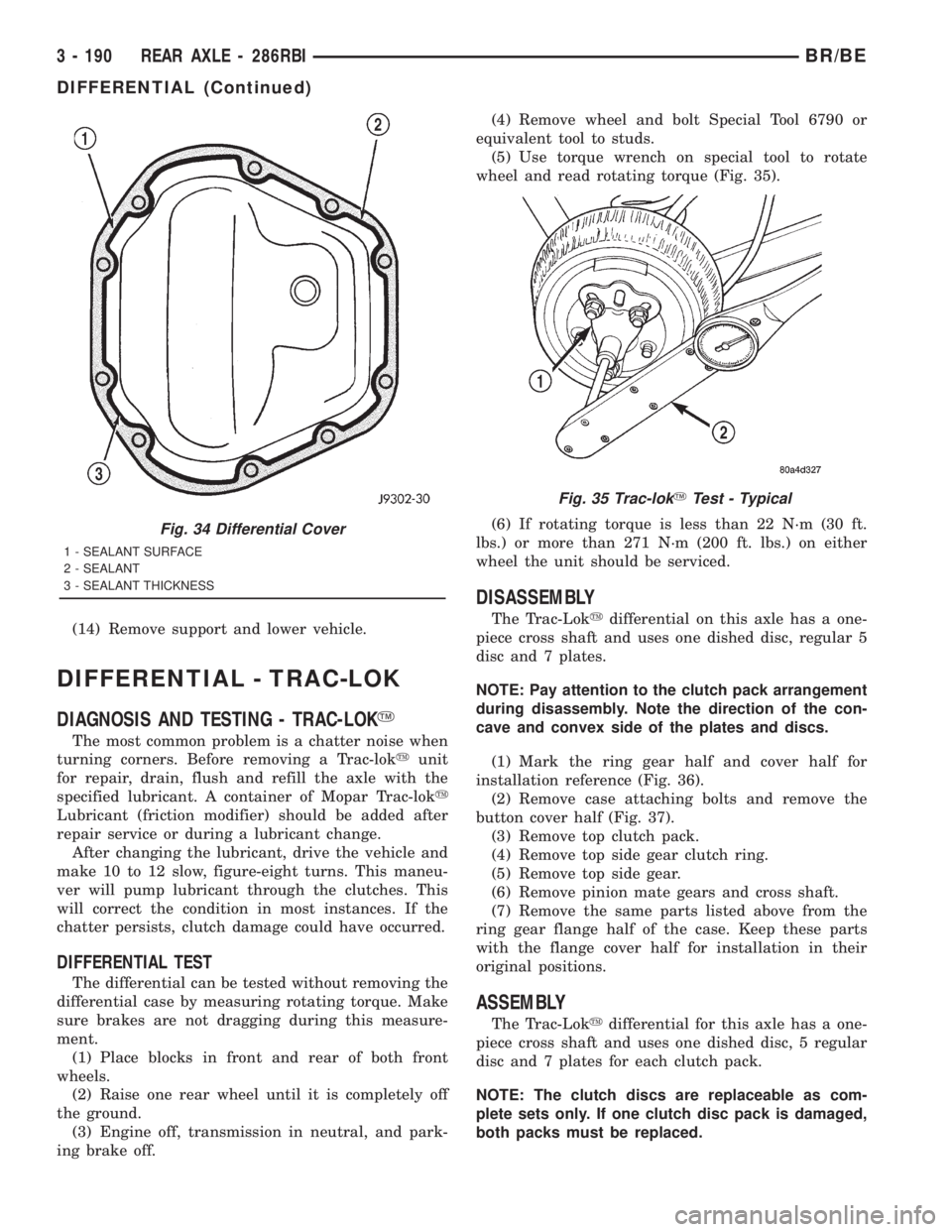
(1) Mark the ring gear half and cover half for
installation reference (Fig. 36).
(2) Remove case attaching bolts and remove the
button cover half (Fig. 37).
(3) Remove top clutch pack.
(4) Remove top side gear clutch ring.
(5) Remove top side gear.
(6) Remove pinion mate gears and cross shaft.
(7) Remove the same parts listed above from the
ring gear flange half of the case. Keep these parts
with the flange cover half for installation in their
original positions.
ASSEMBLY
The Trac-Lokydifferential for this axle has a one-
piece cross shaft and uses one dished disc, 5 regular
disc and 7 plates for each clutch pack.
NOTE: The clutch discs are replaceable as com-
plete sets only. If one clutch disc pack is damaged,
both packs must be replaced.
Fig. 34 Differential Cover
1 - SEALANT SURFACE
2 - SEALANT
3 - SEALANT THICKNESS
Fig. 35 Trac-lokYTest - Typical
3 - 190 REAR AXLE - 286RBIBR/BE
DIFFERENTIAL (Continued)
Page 282 of 2889
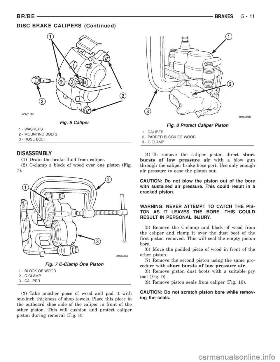
DISASSEMBLY
(1) Drain the brake fluid from caliper.
(2) C-clamp a block of wood over one piston (Fig.
7).
(3) Take another piece of wood and pad it with
one-inch thickness of shop towels. Place this piece in
the outboard shoe side of the caliper in front of the
other piston. This will cushion and protect caliper
piston during removal (Fig. 8).(4) To remove the caliper piston directshort
bursts of low pressure airwith a blow gun
through the caliper brake hose port. Use only enough
air pressure to ease the piston out.
CAUTION: Do not blow the piston out of the bore
with sustained air pressure. This could result in a
cracked piston.
WARNING: NEVER ATTEMPT TO CATCH THE PIS-
TON AS IT LEAVES THE BORE. THIS COULD
RESULT IN PERSONAL INJURY.
(5) Remove the C-clamp and block of wood from
the caliper and clamp it over the dust boot of the
first piston removed. This will seal the empty piston
bore.
(6) Move the padded piece of wood in front of the
other piston.
(7) Remove the second piston using the same pro-
cedure withshort bursts of low pressure air.
(8) Remove piston dust boots with a suitable pry
tool (Fig. 9).
(9) Remove piston seals from caliper (Fig. 10).
CAUTION: Do not scratch piston bore while remov-
ing the seals.
Fig. 6 Caliper
1 - WASHERS
2 - MOUNTING BOLTS
3 - HOSE BOLT
Fig. 7 C-Clamp One Piston
1 - BLOCK OF WOOD
2 - C-CLAMP
3 - CALIPER
Fig. 8 Protect Caliper Piston
1 - CALIPER
2 - PADDED BLOCK OF WOOD
3 - C-CLAMP
BR/BEBRAKES 5 - 11
DISC BRAKE CALIPERS (Continued)
Page 285 of 2889
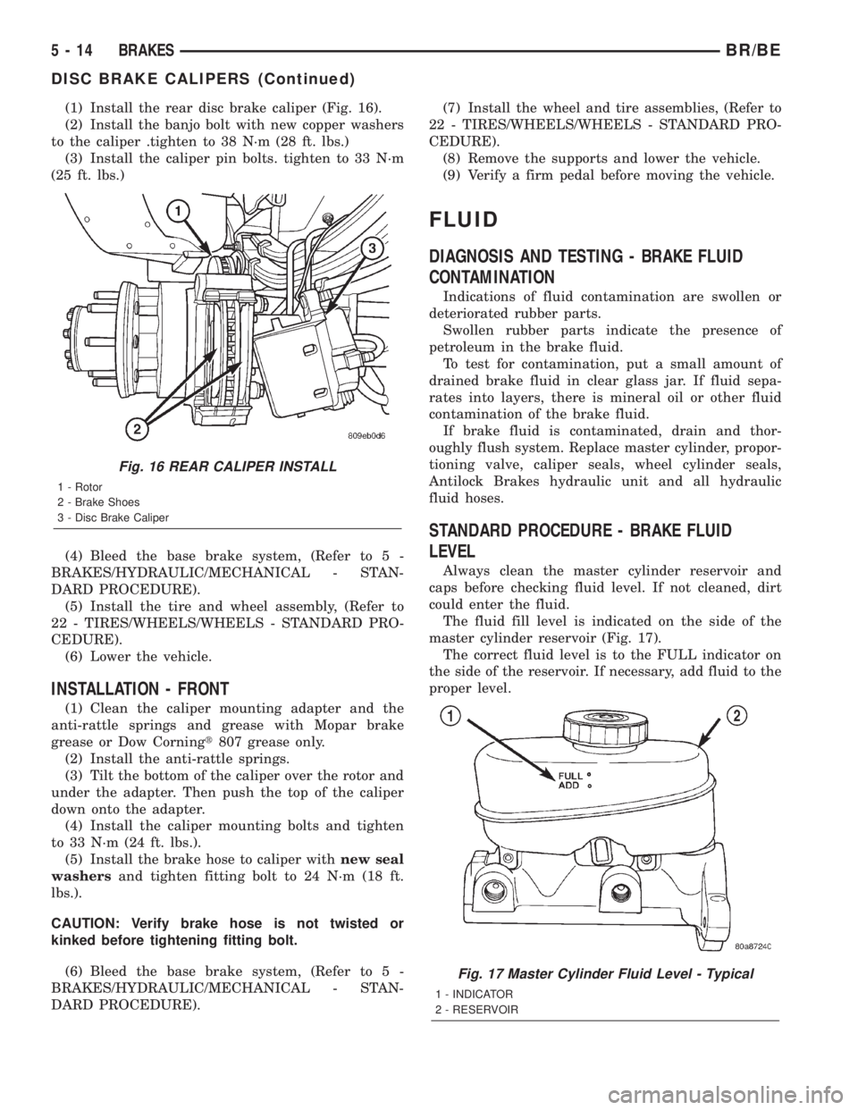
(1) Install the rear disc brake caliper (Fig. 16).
(2) Install the banjo bolt with new copper washers
to the caliper .tighten to 38 N´m (28 ft. lbs.)
(3) Install the caliper pin bolts. tighten to 33 N´m
(25 ft. lbs.)
(4) Bleed the base brake system, (Refer to 5 -
BRAKES/HYDRAULIC/MECHANICAL - STAN-
DARD PROCEDURE).
(5) Install the tire and wheel assembly, (Refer to
22 - TIRES/WHEELS/WHEELS - STANDARD PRO-
CEDURE).
(6) Lower the vehicle.
INSTALLATION - FRONT
(1) Clean the caliper mounting adapter and the
anti-rattle springs and grease with Mopar brake
grease or Dow Corningt807 grease only.
(2) Install the anti-rattle springs.
(3) Tilt the bottom of the caliper over the rotor and
under the adapter. Then push the top of the caliper
down onto the adapter.
(4) Install the caliper mounting bolts and tighten
to 33 N´m (24 ft. lbs.).
(5) Install the brake hose to caliper withnew seal
washersand tighten fitting bolt to 24 N´m (18 ft.
lbs.).
CAUTION: Verify brake hose is not twisted or
kinked before tightening fitting bolt.
(6) Bleed the base brake system, (Refer to 5 -
BRAKES/HYDRAULIC/MECHANICAL - STAN-
DARD PROCEDURE).(7) Install the wheel and tire assemblies, (Refer to
22 - TIRES/WHEELS/WHEELS - STANDARD PRO-
CEDURE).
(8) Remove the supports and lower the vehicle.
(9) Verify a firm pedal before moving the vehicle.
FLUID
DIAGNOSIS AND TESTING - BRAKE FLUID
CONTAMINATION
Indications of fluid contamination are swollen or
deteriorated rubber parts.
Swollen rubber parts indicate the presence of
petroleum in the brake fluid.
To test for contamination, put a small amount of
drained brake fluid in clear glass jar. If fluid sepa-
rates into layers, there is mineral oil or other fluid
contamination of the brake fluid.
If brake fluid is contaminated, drain and thor-
oughly flush system. Replace master cylinder, propor-
tioning valve, caliper seals, wheel cylinder seals,
Antilock Brakes hydraulic unit and all hydraulic
fluid hoses.
STANDARD PROCEDURE - BRAKE FLUID
LEVEL
Always clean the master cylinder reservoir and
caps before checking fluid level. If not cleaned, dirt
could enter the fluid.
The fluid fill level is indicated on the side of the
master cylinder reservoir (Fig. 17).
The correct fluid level is to the FULL indicator on
the side of the reservoir. If necessary, add fluid to the
proper level.
Fig. 16 REAR CALIPER INSTALL
1 - Rotor
2 - Brake Shoes
3 - Disc Brake Caliper
Fig. 17 Master Cylinder Fluid Level - Typical
1 - INDICATOR
2 - RESERVOIR
5 - 14 BRAKESBR/BE
DISC BRAKE CALIPERS (Continued)