2001 DODGE RAM drain bolt
[x] Cancel search: drain boltPage 2433 of 2889
REMOVAL
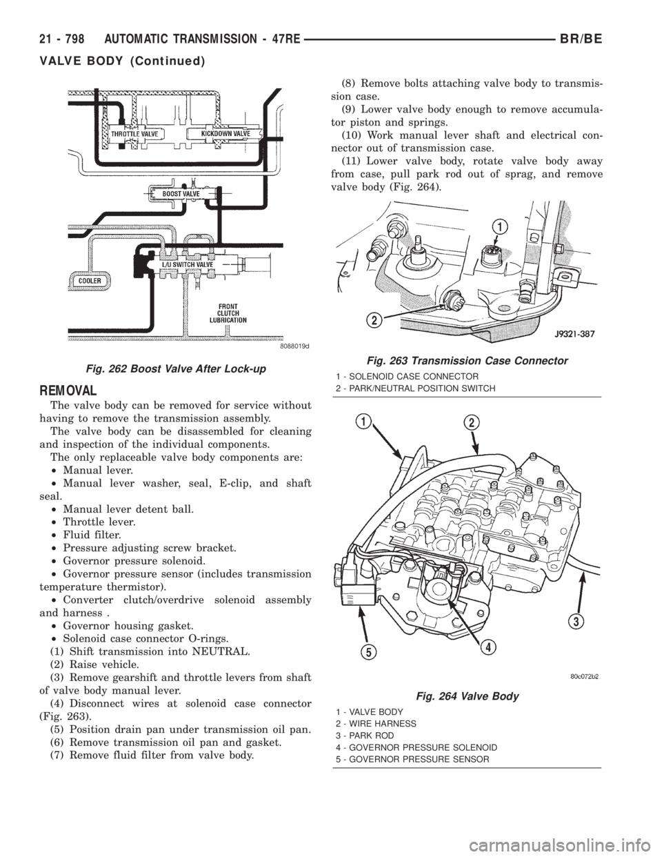
The valve body can be removed for service without
having to remove the transmission assembly.
The valve body can be disassembled for cleaning
and inspection of the individual components.
The only replaceable valve body components are:
²Manual lever.
²Manual lever washer, seal, E-clip, and shaft
seal.
²Manual lever detent ball.
²Throttle lever.
²Fluid filter.
²Pressure adjusting screw bracket.
²Governor pressure solenoid.
²Governor pressure sensor (includes transmission
temperature thermistor).
²Converter clutch/overdrive solenoid assembly
and harness .
²Governor housing gasket.
²Solenoid case connector O-rings.
(1) Shift transmission into NEUTRAL.
(2) Raise vehicle.
(3) Remove gearshift and throttle levers from shaft
of valve body manual lever.
(4) Disconnect wires at solenoid case connector
(Fig. 263).
(5) Position drain pan under transmission oil pan.
(6) Remove transmission oil pan and gasket.
(7) Remove fluid filter from valve body.(8) Remove bolts attaching valve body to transmis-
sion case.
(9) Lower valve body enough to remove accumula-
tor piston and springs.
(10) Work manual lever shaft and electrical con-
nector out of transmission case.
(11) Lower valve body, rotate valve body away
from case, pull park rod out of sprag, and remove
valve body (Fig. 264).
Fig. 262 Boost Valve After Lock-upFig. 263 Transmission Case Connector
1 - SOLENOID CASE CONNECTOR
2 - PARK/NEUTRAL POSITION SWITCH
Fig. 264 Valve Body
1 - VALVE BODY
2 - WIRE HARNESS
3 - PARK ROD
4 - GOVERNOR PRESSURE SOLENOID
5 - GOVERNOR PRESSURE SENSOR
21 - 798 AUTOMATIC TRANSMISSION - 47REBR/BE
VALVE BODY (Continued)
Page 2483 of 2889
SPECIFICATIONS
TRANSFER CASE
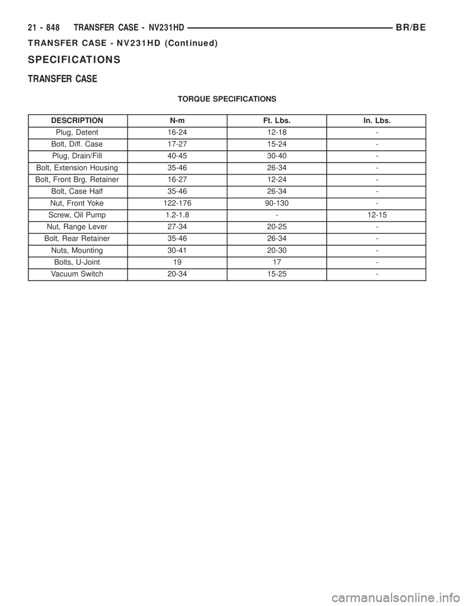
TORQUE SPECIFICATIONS
DESCRIPTION N-m Ft. Lbs. In. Lbs.
Plug, Detent 16-24 12-18 -
Bolt, Diff. Case 17-27 15-24 -
Plug, Drain/Fill 40-45 30-40 -
Bolt, Extension Housing 35-46 26-34 -
Bolt, Front Brg. Retainer 16-27 12-24 -
Bolt, Case Half 35-46 26-34 -
Nut, Front Yoke 122-176 90-130 -
Screw, Oil Pump 1.2-1.8 - 12-15
Nut, Range Lever 27-34 20-25 -
Bolt, Rear Retainer 35-46 26-34 -
Nuts, Mounting 30-41 20-30 -
Bolts, U-Joint 19 17 -
Vacuum Switch 20-34 15-25 -
21 - 848 TRANSFER CASE - NV231HDBR/BE
TRANSFER CASE - NV231HD (Continued)
Page 2493 of 2889
REMOVAL
(1) Raise and support vehicle.
(2) Remove skid plate, if equipped. (Refer to 13 -
FRAMES & BUMPERS/FRAME/TRANSFER CASE
SKID PLATE - REMOVAL)
(3) Position drain oil container under transfer
case.
(4) Remove transfer case drain plug and drain
lubricant into container.
(5) Disconnect vent hose and vacuum harness at
transfer case switch.
(6) Disconnect shift rod from grommet in transfer
case shift lever, or from floor shift arm whichever
provides easy access. Use channel lock style pliers to
press rod out of lever grommet.
(7) Support transmission with jack stand.
(8) Remove rear crossmember.
(9) Mark front and rear propeller shafts for assem-
bly reference.
(10) Remove front and rear propeller shafts. (Refer
to 3 - DIFFERENTIAL & DRIVELINE/PROPELLER
SHAFT/PROPELLER SHAFT - REMOVAL)
(11) Support transfer case with suitable jack.
Secure transfer case to jack with safety chains.
(12) Remove nuts attaching transfer case to trans-
mission.
(13) Move transfer case assembly rearward until
free of transmission output shaft.
(14) Lower jack and move transfer case from
under vehicle.
DISASSEMBLY
Position transfer case in a shallow drain pan.
Remove drain plug and drain any remaining lubri-
cant remaining in case.
REAR EXTENSION, RETAINER, AND REAR CASE
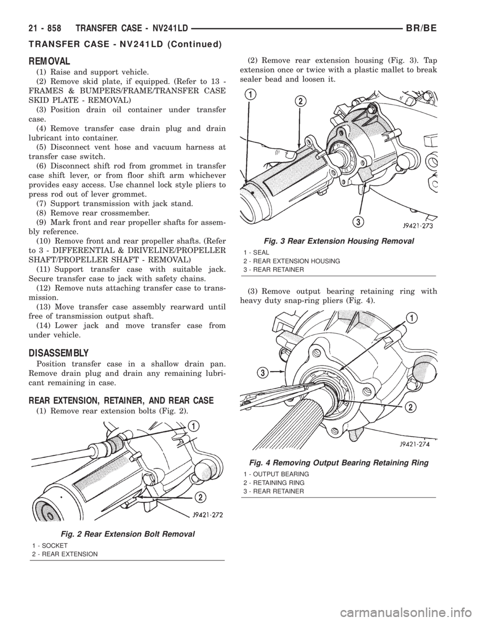
(1) Remove rear extension bolts (Fig. 2).(2) Remove rear extension housing (Fig. 3). Tap
extension once or twice with a plastic mallet to break
sealer bead and loosen it.
(3) Remove output bearing retaining ring with
heavy duty snap-ring pliers (Fig. 4).
Fig. 2 Rear Extension Bolt Removal
1 - SOCKET
2 - REAR EXTENSION
Fig. 3 Rear Extension Housing Removal
1 - SEAL
2 - REAR EXTENSION HOUSING
3 - REAR RETAINER
Fig. 4 Removing Output Bearing Retaining Ring
1 - OUTPUT BEARING
2 - RETAINING RING
3 - REAR RETAINER
21 - 858 TRANSFER CASE - NV241LDBR/BE
TRANSFER CASE - NV241LD (Continued)
Page 2518 of 2889
SPECIFICATIONS
TRANSFER CASE
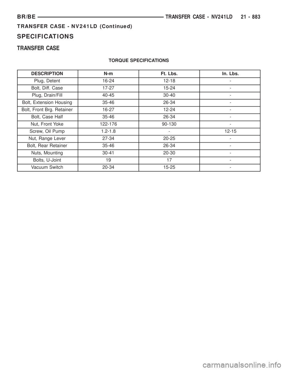
TORQUE SPECIFICATIONS
DESCRIPTION N-m Ft. Lbs. In. Lbs.
Plug, Detent 16-24 12-18 -
Bolt, Diff. Case 17-27 15-24 -
Plug, Drain/Fill 40-45 30-40 -
Bolt, Extension Housing 35-46 26-34 -
Bolt, Front Brg. Retainer 16-27 12-24 -
Bolt, Case Half 35-46 26-34 -
Nut, Front Yoke 122-176 90-130 -
Screw, Oil Pump 1.2-1.8 - 12-15
Nut, Range Lever 27-34 20-25 -
Bolt, Rear Retainer 35-46 26-34 -
Nuts, Mounting 30-41 20-30 -
Bolts, U-Joint 19 17 -
Vacuum Switch 20-34 15-25 -
BR/BETRANSFER CASE - NV241LD 21 - 883
TRANSFER CASE - NV241LD (Continued)
Page 2529 of 2889
REMOVAL
(1) Raise and support vehicle.
(2) Remove skid plate, if equipped. (Refer to 13 -
FRAMES & BUMPERS/FRAME/TRANSFER CASE
SKID PLATE - REMOVAL)
(3) Position drain oil container under transfer
case.
(4) Remove transfer case drain plug and drain
lubricant into container.
(5) Disconnect vent hose and vacuum harness at
transfer case switch.
(6) Disconnect shift rod from grommet in transfer
case shift lever, or from floor shift arm whichever
provides easy access. Use channel lock style pliers to
press rod out of lever grommet.
(7) Support transmission with jack stand.
(8) Remove rear crossmember.
(9) Mark front and rear propeller shafts for assem-
bly reference.
(10) Remove front and rear propeller shafts. (Refer
to 3 - DIFFERENTIAL & DRIVELINE/PROPELLER
SHAFT/PROPELLER SHAFT - REMOVAL)
(11) Support transfer case with suitable jack.
Secure transfer case to jack with safety chains.
(12) Remove nuts attaching transfer case to trans-
mission.
(13) Move transfer case assembly rearward until
free of transmission output shaft.
(14) Lower jack and move transfer case from
under vehicle.
DISASSEMBLY
Position transfer case in a shallow drain pan.
Remove drain plug and drain any remaining lubri-
cant remaining in case.
EXTENSION HOUSING
(1) Remove extension housing snap-ring access
cover.
(2) Remove bolts holding extension housing to rear
case half.
(3) Tap extension housing with plastic or rawhide
hammer to loosen sealant.
(4) Disengage extension housing snap-ring from
rear output shaft bearing.
(5) Separate extension housing from transfer case.
COMPANION FLANGE AND SHIFT LEVER
(1) Shift transfer case into NEUTRAL.
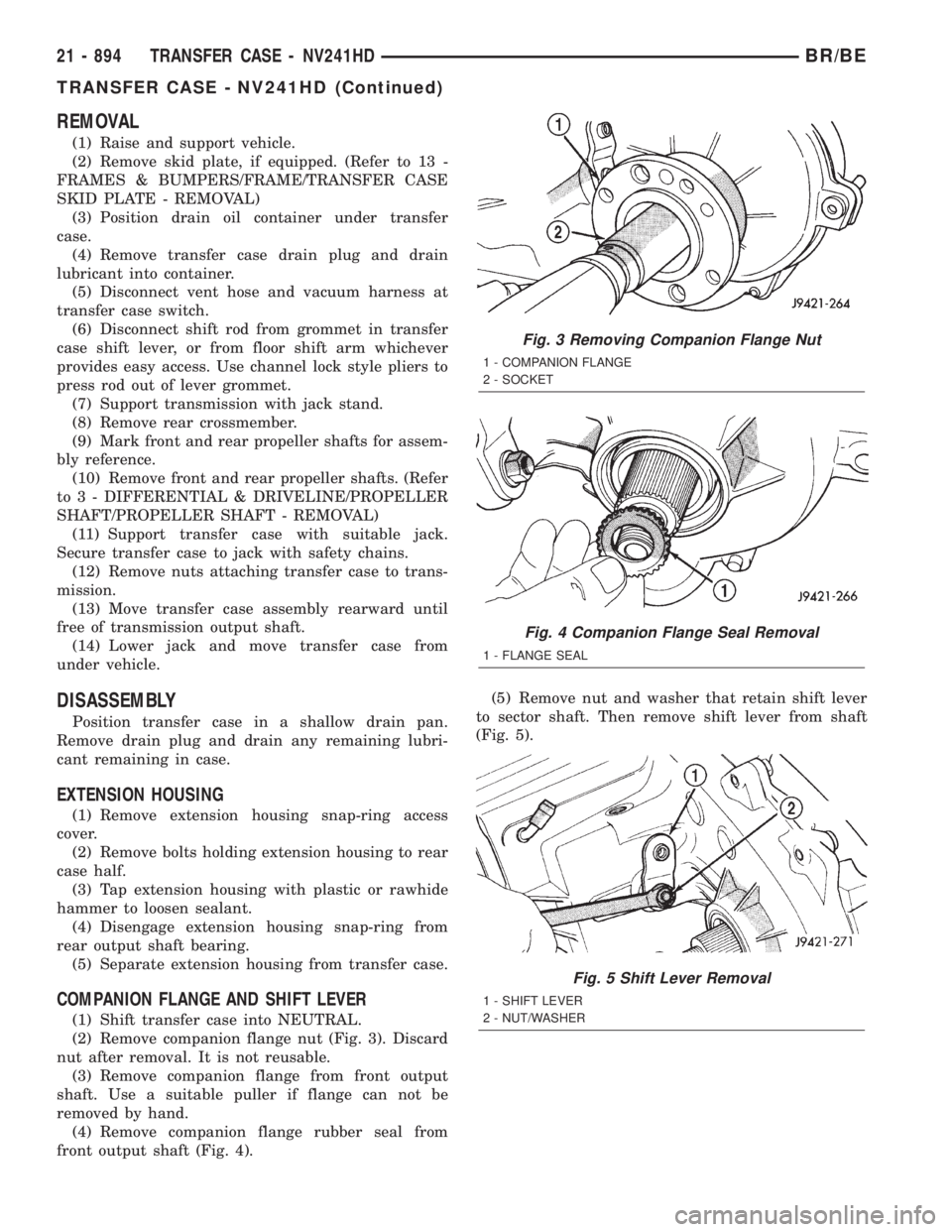
(2) Remove companion flange nut (Fig. 3). Discard
nut after removal. It is not reusable.
(3) Remove companion flange from front output
shaft. Use a suitable puller if flange can not be
removed by hand.
(4) Remove companion flange rubber seal from
front output shaft (Fig. 4).(5) Remove nut and washer that retain shift lever
to sector shaft. Then remove shift lever from shaft
(Fig. 5).
Fig. 3 Removing Companion Flange Nut
1 - COMPANION FLANGE
2 - SOCKET
Fig. 4 Companion Flange Seal Removal
1 - FLANGE SEAL
Fig. 5 Shift Lever Removal
1 - SHIFT LEVER
2 - NUT/WASHER
21 - 894 TRANSFER CASE - NV241HDBR/BE
TRANSFER CASE - NV241HD (Continued)
Page 2554 of 2889
(7) Apply MopartSilicone Sealer to mating surface
of PTO cover and to cover bolt shanks and underside
of bolt heads. Then install and tighten bolts to 27-34
N´m (20-25 ft. lbs.) torque.
INSTALLATION
(1) Align and seat transfer case on transmission.
Be sure transfer case input gear splines are aligned
with transmission output shaft. Align splines by
rotating transfer case rear output shaft yoke if nec-
essary. Do not install any transfer case attaching
nuts until the transfer case is completely seated
against the transmission.
(2) Install and tighten transfer case attaching
nuts. Tighten nuts to 30-41 N´m (20-30 ft.lbs.).
(3) Install rear crossmember.(4) Remove jack stand from under transmission.
(5) Align and connect propeller shafts. (Refer to 3 -
DIFFERENTIAL & DRIVELINE/PROPELLER
SHAFT/PROPELLER SHAFT - INSTALLATION)
(6) Connect vacuum harness and vent hose.
(7) Connect shift rod to transfer case lever or floor
shift arm. Use channel lock style pliers to press rod
back into lever grommet.
(8) Adjust shift linkage, if necessary.
(9) Fill transfer case with recommended transmis-
sion fluid and install fill plug.
(10) Install skid plate, if equipped. (Refer to 13 -
FRAMES & BUMPERS/FRAME/TRANSFER CASE
SKID PLATE - INSTALLATION)
(11) Lower vehicle
SPECIFICATIONS
TRANSFER CASE
TORQUE SPECIFICATIONS
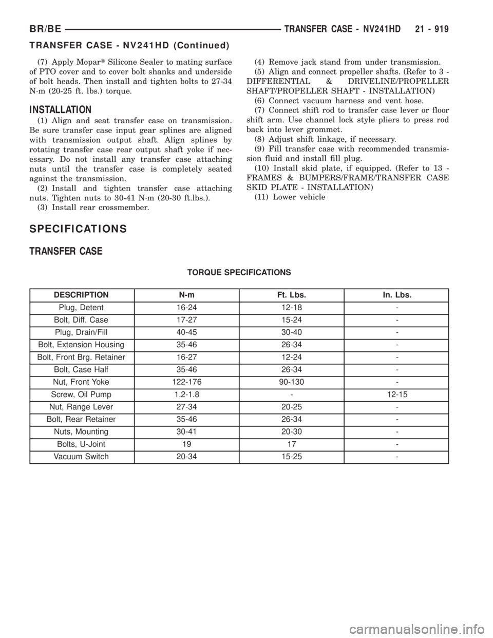
DESCRIPTION N-m Ft. Lbs. In. Lbs.
Plug, Detent 16-24 12-18 -
Bolt, Diff. Case 17-27 15-24 -
Plug, Drain/Fill 40-45 30-40 -
Bolt, Extension Housing 35-46 26-34 -
Bolt, Front Brg. Retainer 16-27 12-24 -
Bolt, Case Half 35-46 26-34 -
Nut, Front Yoke 122-176 90-130 -
Screw, Oil Pump 1.2-1.8 - 12-15
Nut, Range Lever 27-34 20-25 -
Bolt, Rear Retainer 35-46 26-34 -
Nuts, Mounting 30-41 20-30 -
Bolts, U-Joint 19 17 -
Vacuum Switch 20-34 15-25 -
BR/BETRANSFER CASE - NV241HD 21 - 919
TRANSFER CASE - NV241HD (Continued)
Page 2671 of 2889
SIDE VIEW MIRROR - LOW
MOUNTED
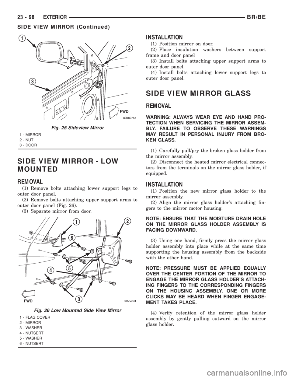
REMOVAL
(1) Remove bolts attaching lower support legs to
outer door panel.
(2) Remove bolts attaching upper support arms to
outer door panel (Fig. 26).
(3) Separate mirror from door.
INSTALLATION
(1) Position mirror on door.
(2) Place insulation washers between support
frame and door panel
(3) Install bolts attaching upper support arms to
outer door panel.
(4) Install bolts attaching lower support legs to
outer door panel.
SIDE VIEW MIRROR GLASS
REMOVAL
WARNING: ALWAYS WEAR EYE AND HAND PRO-
TECTION WHEN SERVICING THE MIRROR ASSEM-
BLY. FAILURE TO OBSERVE THESE WARNINGS
MAY RESULT IN PERSONAL INJURY FROM BRO-
KEN GLASS.
(1) Carefully pull/pry the broken glass holder from
the mirror assembly.
(2) Disconnect the heated mirror electrical connec-
tors from the terminals on the mirror glass holder, if
equipped.
INSTALLATION
(1) Position the new mirror glass holder to the
mirror assembly.
(2) Align the mirror glass holder's attaching fin-
gers to the mirror motor housing.
NOTE: ENSURE THAT THE MOISTURE DRAIN HOLE
ON THE MIRROR GLASS HOLDER ASSEMBLY IS
FACING DOWNWARD.
(3) Using one hand, firmly press the mirror glass
holder assembly into place while at the same time
supporting the housing assembly from the backside
with the other hand.
NOTE: PRESSURE MUST BE APPLIED EQUALLY
OVER THE CENTER PORTION OF THE MIRROR TO
ENGAGE THE MIRROR GLASS HOLDER'S ATTACH-
ING FINGERS TO THE CORRESPONDING FINGERS
ON THE HOUSING ASSEMBLY. ONE OR MORE
CLICKS MAY BE HEARD WHEN FINGER ENGAGE-
MENT TAKES PLACE.
(4) Verify retention of the mirror glass holder
assembly by gently pulling outward on the mirror
glass holder.
Fig. 25 Sideview Mirror
1 - MIRROR
2 - NUT
3 - DOOR
Fig. 26 Low Mounted Side View Mirror
1 - FLAG COVER
2 - MIRROR
3 - WASHER
4 - NUTSERT
5 - WASHER
6 - NUTSERT
23 - 98 EXTERIORBR/BE
SIDE VIEW MIRROR (Continued)