2001 DODGE RAM warning lights
[x] Cancel search: warning lightsPage 447 of 2889
²Head/Park Lights-On Warning- The CTM
chime tone generator will generate repetitive chime
tones at a fast rate to announce that hard wired
inputs from the driver door ajar switch, headlamp
switch, and ignition switch indicate that the exterior
lamps are turned On with the driver side front door
opened and the ignition switch in the Off position.
The chimes will continue to sound until the exterior
lamps are turned Off, the driver side front door is
closed, or the ignition switch is turned to the On
position, whichever occurs first.
²Key-In-Ignition Warning- The BCM chime
tone generator will generate repetitive chime tones at
a fast rate to announce that hard wired inputs from
the driver door ajar switch, headlamp switch, and
ignition switch indicate that the key is in the ignition
lock cylinder with the driver side front door opened
and the ignition switch in the Off position. The
chimes will continue to sound until the key is
removed from the ignition lock cylinder, the driver
side front door is closed, or the ignition switch is
turned to the On position, whichever occurs first.
²Warning Chime Support- The CTM chime
tone generator will generate repetitive chime tones at
a slow rate to announce that a hard wired chime
request input has been received from the EMIC.
These chime tones provide an audible alert to the
vehicle operator that supplements certain visual indi-
cations displayed by the EMIC. Supplemented indica-
tions include the following:
²The ªAirbagº indicator is illuminated. The
chimes will continue to sound for a duration of about
four seconds each time the indicator is illuminated or
until the ignition switch is turned to the Off position,
whichever occurs first.
²The ªCheck Gagesº indicator is illuminated. The
chimes will continue to sound for a duration of about
two seconds each time the indicator is illuminated or
until the ignition switch is turned to the Off position,
whichever occurs first.
²The ªLow Fuelº indicator is illuminated. The
chimes will continue to sound for a duration of about
two seconds each time the indicator is illuminated or
until the ignition switch is turned to the Off position,
whichever occurs first.
²The ªLow Washº indicator is illuminated. The
chimes will continue to sound for a duration of about
two seconds each time the indicator is illuminated or
until the ignition switch is turned to the Off position,
whichever occurs first.
²The ªTrans Tempº indicator is illuminated (auto-
matic transmission only). The chimes will continue to
sound for a duration of about two seconds each time
the indicator is illuminated or until the ignition
switch is turned to the Off position, whichever occurs
first.²The vehicle is over a programmed speed value
(Middle East Gulf Coast Country (GCC) only). The
CTM chime tone generator will generate repetitive
chime tones at a slow rate to announce that the vehi-
cle speed exceeds a programmed value. The chimes
will continue to sound until the vehicle speed is
below the programmed value.
²The ªWater-In-Fuelº indicator is illuminated
(diesel engine only). The chimes will continue to
sound for a duration of about two seconds each time
the indicator is illuminated or until the ignition
switch is turned to the Off position, whichever occurs
first.
The CTM provides chime service for all available
features in the chime warning system. The CTM
relies upon hard wired inputs from the driver door
ajar switch, the EMIC, the headlamp switch, and the
key-in ignition switch (ignition switch) to provide
chime service for all of the chime warning system
features. Upon receiving the proper inputs, the CTM
activates the integral chime tone generator to pro-
vide the audible chime tone to the vehicle operator.
The chime tone generator in the CTM is capable of
producing repeated chime tones at two different
rates, slow or fast. The slow chime rate is about fifty
chime tones per minute, while the fast chime rate is
about 180 chime tones per minute. The internal pro-
gramming of the CTM and the EMIC determines the
priority of each chime tone request input that is
received, as well as the rate and duration of each
chime tone that is to be generated.
The hard wired chime warning system inputs to
the CTM and the EMIC, as well as other hard wired
circuits for this system may be diagnosed and tested
using conventional diagnostic tools and procedures.
See the owner's manual in the vehicle glove box for
more information on the features provided by the
chime warning system.
DIAGNOSIS AND TESTING - CHIME WARNING
SYSTEM
Refer to the appropriate wiring information. The
wiring information includes wiring diagrams, proper
wire and connector repair procedures, further details
on wire harness routing and retention, as well as
pin-out and location views for the various wire har-
ness connectors, splices and grounds. The hard wired
chime warning system inputs to the Central Timer
Module (CTM) and the Electro-Mechanical Instru-
ment Cluster (EMIC), as well as other hard wired
circuits for this system may be diagnosed and tested
using conventional diagnostic tools and procedures.
8B - 2 CHIME/BUZZERBR/BE
CHIME WARNING SYSTEM (Continued)
Page 604 of 2889
COMBINATION FLASHER
DESCRIPTION
The combination flasher is located in the Junction
Block (JB) behind the fuse access panel on the left
outboard end of the instrument panel. The combina-
tion flasher is a smart relay that functions as both
the turn signal system and the hazard warning sys-
tem flasher. The combination flasher contains active
electronic Integrated Circuitry (IC) elements. This
flasher is designed to handle the current flow
requirements of the factory-installed lighting. If sup-
plemental lighting is added to the turn signal lamp
circuits, such as when towing a trailer with lights,
the combination flasher will automatically try to
compensate to keep the flash rate the same.
The combination flasher has five blade-type termi-
nals that connect it to the vehicle electrical system
through five matching cavities in the receptacle of
the JB. While the combination flasher has a Interna-
tional Standards Organization (ISO)-type relay ter-
minal configuration or footprint, the internal
circuitry is much different. The combination flasher
does not use standard ISO-relay inputs or provide
ISO-relay type outputs or functions. The combination
flasher should never be substituted for an ISO-relay
or replaced with an ISO-relay, or else component and
vehicle damage may occur.
The combination flasher cannot be repaired or
adjusted and, if faulty or damaged, it must be
replaced.
OPERATION
The combination flasher has five blade-type termi-
nals intended for the following inputs and outputs:
fused B(+), fused ignition switch output, ground, turn
signal circuit, and hazard warning circuit. Constant
battery voltage and ground are supplied to the
flasher so that it can perform the hazard warning
function, and ignition switched battery voltage is
supplied for the turn signal function.
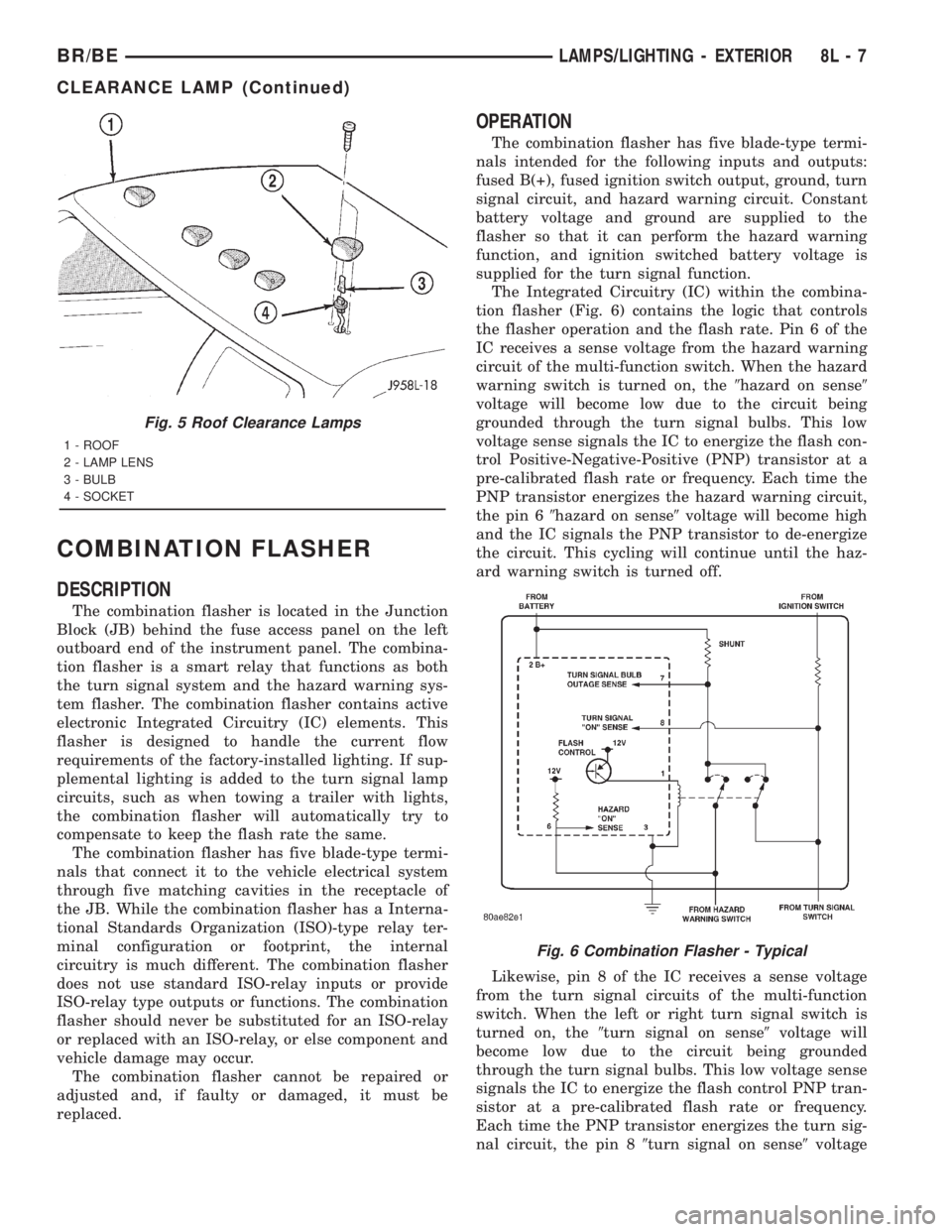
The Integrated Circuitry (IC) within the combina-
tion flasher (Fig. 6) contains the logic that controls
the flasher operation and the flash rate. Pin 6 of the
IC receives a sense voltage from the hazard warning
circuit of the multi-function switch. When the hazard
warning switch is turned on, the9hazard on sense9
voltage will become low due to the circuit being
grounded through the turn signal bulbs. This low
voltage sense signals the IC to energize the flash con-
trol Positive-Negative-Positive (PNP) transistor at a
pre-calibrated flash rate or frequency. Each time the
PNP transistor energizes the hazard warning circuit,
the pin 69hazard on sense9voltage will become high
and the IC signals the PNP transistor to de-energize
the circuit. This cycling will continue until the haz-
ard warning switch is turned off.
Likewise, pin 8 of the IC receives a sense voltage
from the turn signal circuits of the multi-function
switch. When the left or right turn signal switch is
turned on, the9turn signal on sense9voltage will
become low due to the circuit being grounded
through the turn signal bulbs. This low voltage sense
signals the IC to energize the flash control PNP tran-
sistor at a pre-calibrated flash rate or frequency.
Each time the PNP transistor energizes the turn sig-
nal circuit, the pin 89turn signal on sense9voltage
Fig. 5 Roof Clearance Lamps
1 - ROOF
2 - LAMP LENS
3 - BULB
4 - SOCKET
Fig. 6 Combination Flasher - Typical
BR/BELAMPS/LIGHTING - EXTERIOR 8L - 7
CLEARANCE LAMP (Continued)
Page 2575 of 2889
DIAGNOSIS AND TESTING ± WATER LEAKS
Water leaks can be caused by poor sealing,
improper body component alignment, body seam
porosity, missing plugs, or blocked drain holes. Cen-
trifugal and gravitational force can cause water to
drip from a location away from the actual leak point,
making leak detection difficult. All body sealing
points should be water tight in normal wet-driving
conditions. Water flowing downward from the front of
the vehicle should not enter the passenger or luggage
compartment. Moving sealing surfaces will not
always seal water tight under all conditions. At
times, side glass or door seals will allow water to
enter the passenger compartment during high pres-
sure washing or hard driving rain (severe) condi-
tions. Overcompensating on door or glass
adjustments to stop a water leak that occurs under
severe conditions can cause premature seal wear and
excessive closing or latching effort. After completing
a repair, water test vehicle to verify leak has stopped
before returning vehicle to use.
VISUAL INSPECTION BEFORE WATER LEAK TESTS
Verify that floor and body plugs are in place, body
drains are clear, and body components are properly
aligned and sealed. If component alignment or seal-
ing is necessary, refer to the appropriate section of
this group for proper procedures.
WATER LEAK TESTS
WARNING: DO NOT USE ELECTRIC SHOP LIGHTS
OR TOOLS IN WATER TEST AREA. PERSONAL
INJURY CAN RESULT.
When the conditions causing a water leak have
been determined, simulate the conditions as closely
as possible.
²If a leak occurs with the vehicle parked in a
steady light rain, flood the leak area with an open-
ended garden hose.
²If a leak occurs while driving at highway speeds
in a steady rain, test the leak area with a reasonable
velocity stream or fan spray of water. Direct the
spray in a direction comparable to actual conditions.
²If a leak occurs when the vehicle is parked on an
incline, hoist the end or side of the vehicle to simu-
late this condition. This method can be used when
the leak occurs when the vehicle accelerates, stops or
turns. If the leak occurs on acceleration, hoist the
front of the vehicle. If the leak occurs when braking,
hoist the back of the vehicle. If the leak occurs on left
turns, hoist the left side of the vehicle. If the leak
occurs on right turns, hoist the right side of the vehi-
cle. For hoisting recommendations refer to Group 0,
Lubrication and Maintenance, General Information
section.
WATER LEAK DETECTION
To detect a water leak point-of-entry, do a water
test and watch for water tracks or droplets forming
on the inside of the vehicle. If necessary, remove inte-
rior trim covers or panels to gain visual access to the
leak area. If the hose cannot be positioned without
being held, have someone help do the water test.
Some water leaks must be tested for a considerable
length of time to become apparent. When a leak
appears, find the highest point of the water track or
drop. The highest point usually will show the point of
entry. After leak point has been found, repair the
leak and water test to verify that the leak has
stopped.
Locating the entry point of water that is leaking
into a cavity between panels can be difficult. The
trapped water may splash or run from the cavity,
often at a distance from the entry point. Most water
leaks of this type become apparent after accelerating,
stopping, turning, or when on an incline.
MIRROR INSPECTION METHOD
When a leak point area is visually obstructed, use
a suitable mirror to gain visual access. A mirror can
also be used to deflect light to a limited-access area
to assist in locating a leak point.
BRIGHT LIGHT LEAK TEST METHOD
Some water leaks in the luggage compartment can
be detected without water testing. Position the vehi-
cle in a brightly lit area. From inside the darkened
luggage compartment inspect around seals and body
seams. If necessary, have a helper direct a drop light
over the suspected leak areas around the luggage
compartment. If light is visible through a normally
sealed location, water could enter through the open-
ing.
PRESSURIZED LEAK TEST METHOD
When a water leak into the passenger compart-
ment cannot be detected by water testing, pressurize
the passenger compartment and soap test exterior of
the vehicle. To pressurize the passenger compart-
ment, close all doors and windows, start engine, and
set heater control to high blower in HEAT position. If
engine can not be started, connect a charger to the
battery to ensure adequate voltage to the blower.
With interior pressurized, apply dish detergent solu-
tion to suspected leak area on the exterior of the
vehicle. Apply detergent solution with spray device or
soft bristle brush. If soap bubbles occur at a body
seam, joint, seal or gasket, the leak entry point could
be at that location.
23 - 2 BODYBR/BE
BODY (Continued)
Page 2840 of 2889
ROAD TEST
DESCRIPTION - ROAD TEST INSPECTION
The following items must be inspected during the
road test portion of the new vehicle inspection.
²Check neutral safety switch operation
²Check operation of shift/clutch interlock system
²Check operation of gauges and warning lights
²Check horn operation
²Check operation of turn signals and emergency
flashers
²Check all mirror adjustments, including day/
night function
²Check windshield wipers for proper wipe pattern
and intermittent mode (if equipped)
²Check washer spray pattern
²Check heater, defroster and air conditioning for
proper operation
²Check that the fan operates quietly
²Check the rear window defroster (if equipped)
²Leave air selection lever in the fresh air position
²Check the rear heater and air conditioning for
proper operation
²Check the rear air register locations
²Check that the indicator lamps operate properly
²Check the operation of the radio, cassette and/or
compact disc player, and that sound quality is good
²Ensure that the clock displays the correct time
²Check that the trip computer/maintenance
reminder operates in all modes
²Check all speed control functions
²Check the service brakes to ensure that they
stop the vehicle in a straight line, without noise,
shudder or vibration
²Check the brake warning light
²Check the parking brake operation
²Check the engine's performance
²Check the transmission's performance for
smooth, quiet operation. If the vehicle is a 4x4, check
that the transfer case shifts easily among all ranges
²Check Autostick function (if equipped)
²Check the vehicle's steering and handling
²The steering wheel should be centered when
traveling in a straight line
²The vehicle should not pull or vibrate
²Check for squeaks, rattles and wind noise
²Check any other vehicle aspects you believe are
important, but that may not be included on the New
Vehicle Preparation Form
²Fill fuel tank with specified grade of fuel
INSPECTION - FUEL
Fill fuel tank with specified grade of gasoline (reg-
ular, midgrade or premium).
INSPECTION - OTHER
As part of DaimlerChrysler's Customer One philos-
ophy, the ªOtherº blank is provided on the New Vehi-
cle Preparation Form. This is designed to encourage
you to check any aspects of vehicle operation that
you believe are important to your customers, but that
do not appear elsewhere on the form.
INSPECTION - SQUEAKS, RATTLES AND WIND
NOISE
(1) Make sure that the instrument panel, glove
box, seats, steering wheel and column are free from
squeaks and rattles. Tighten any obvious loose fas-
teners.
(2) Check that the windows and doors are free
from squeaks, rattles and wind noise.
(3) Check that the vehicle exterior is free from
squeaks, rattles and noise, front and rear.
(4) Make sure that all interior panels are free from
squeaks and rattles.
INSPECTION - STEERING AND HANDLING
(1) Check that the power assist works properly (if
equipped). Steering should not require excessive
effort.
(2) Make sure the steering wheel does not vibrate
at idle or road speed.
(3) Ensure that the steering wheel is centered
when traveling straight ahead.
(4) Check that the vehicle does not drift to one
side.
(5) Make sure that the vehicle does not vibrate/
shake.
INSPECTION - TRANSMISSION/TRANSFER
CASE
AUTOMATIC TRANSMISSION
(1) Make sure that the park lock holds the vehicle
With the vehicle on a grade, put automatic trans-
mission in PARK and slowly release the service
brake to see if park lock holds. If it does not hold, the
transmission requires further service.
(2) Make sure shift lever operates easily/ smoothly
(Fig. 36).
Check for smooth shifting. Check for proper
upshifting and downshifting.
MANUAL TRANSMISSION
(1) Check that the shifter operates easily (Fig. 38).
(2) Make sure that the clutch operates smoothly
(Fig. 37).
(3) Look for proper synchronization.
The gears should not grind.
BR/BENEW VEHICLE PREPARATION 30 - 15
Page 2844 of 2889
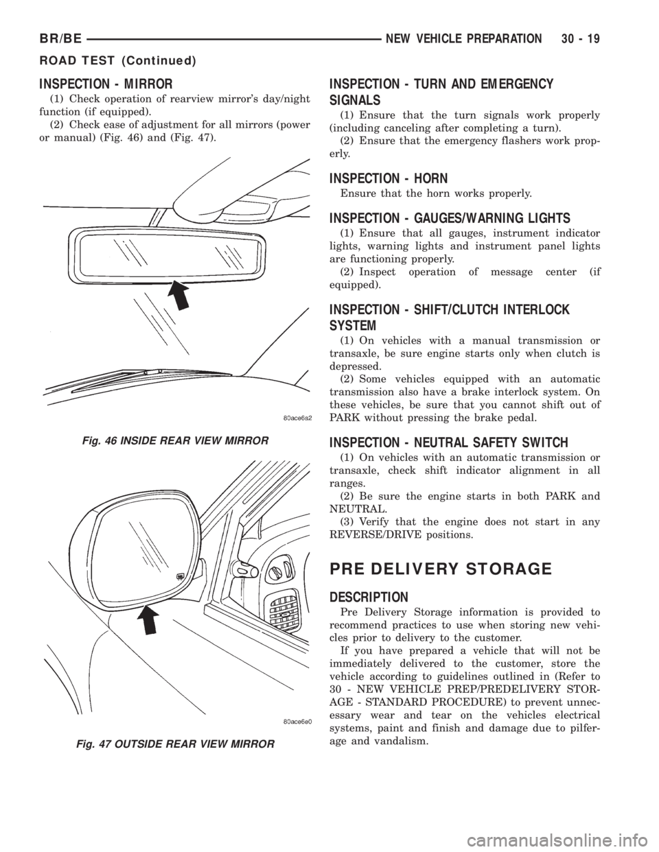
INSPECTION - MIRROR
(1) Check operation of rearview mirror's day/night
function (if equipped).
(2) Check ease of adjustment for all mirrors (power
or manual) (Fig. 46) and (Fig. 47).
INSPECTION - TURN AND EMERGENCY
SIGNALS
(1) Ensure that the turn signals work properly
(including canceling after completing a turn).
(2) Ensure that the emergency flashers work prop-
erly.
INSPECTION - HORN
Ensure that the horn works properly.
INSPECTION - GAUGES/WARNING LIGHTS
(1) Ensure that all gauges, instrument indicator
lights, warning lights and instrument panel lights
are functioning properly.
(2) Inspect operation of message center (if
equipped).
INSPECTION - SHIFT/CLUTCH INTERLOCK
SYSTEM
(1) On vehicles with a manual transmission or
transaxle, be sure engine starts only when clutch is
depressed.
(2) Some vehicles equipped with an automatic
transmission also have a brake interlock system. On
these vehicles, be sure that you cannot shift out of
PARK without pressing the brake pedal.
INSPECTION - NEUTRAL SAFETY SWITCH
(1) On vehicles with an automatic transmission or
transaxle, check shift indicator alignment in all
ranges.
(2) Be sure the engine starts in both PARK and
NEUTRAL.
(3) Verify that the engine does not start in any
REVERSE/DRIVE positions.
PRE DELIVERY STORAGE
DESCRIPTION
Pre Delivery Storage information is provided to
recommend practices to use when storing new vehi-
cles prior to delivery to the customer.
If you have prepared a vehicle that will not be
immediately delivered to the customer, store the
vehicle according to guidelines outlined in (Refer to
30 - NEW VEHICLE PREP/PREDELIVERY STOR-
AGE - STANDARD PROCEDURE) to prevent unnec-
essary wear and tear on the vehicles electrical
systems, paint and finish and damage due to pilfer-
age and vandalism.
Fig. 46 INSIDE REAR VIEW MIRROR
Fig. 47 OUTSIDE REAR VIEW MIRROR
BR/BENEW VEHICLE PREPARATION 30 - 19
ROAD TEST (Continued)
Page 2846 of 2889

Remote Keyless Entry (RKE). The horn chirps when
the vehicle is locked with the RKE transmitter.
HEADLAMP FLASH
NOTE: This feature can be enabled with or without
the horn chirp feature.
The headlamp flash function is a feature that can
be enabled or disabled on vehicles equipped with
Remote Keyless Entry (RKE). The headlamps flash
once when the vehicle is locked with the RKE trans-
mitter, and flash twice when the vehicle is unlocked
with the RKE transmitter.
LOW FUEL CHIME
All vehicles equipped with the audible low fuel
chime are shipped with this feature enabled.
REMOTE KEYLESS ENTRY (RKE) DOOR UNLOCK
SEQUENCE
Two door unlock sequences are provided on vehi-
cles equipped with this feature. When using the RKE
transmitter to unlock the doors, pressing the unlock
button once when the feature is enabled unlocks only
the driver's door. Pushing the RKE transmitter
unlock button a second time unlocks the remaining
doors. When the RKE door unlock feature is disabled,
all doors unlock with one press of the RKE transmit-
ter unlock button.
HEADLIGHTS ON AUTOMATICALLY WITH WIPERS
This feature appears on vehicles that have, as an
option, automatic headlights. When the windshield
wipers are turned on, the headlights automatically
turn on.
12V POWER OUTLET
This feature currently appears on Caravan/Voyag-
er/Town and Country vehicles. The vehicles are
shipped with the 12V power outlets turned off with
the ignition key. The relay can be changed to make
the outlets powered at all times. This feature may be
of interest to customers with cell phones.
TURN SIGNAL CHIME
This feature is an audible turn signal warning
chime. The chime sounds if the turn signal is on, the
vehicle has traveled one mile and vehicle speed has
exceeded 40 Km/h (25 mph).
REMOTE UNLOCK
The remote unlock function is a feature that can be
enabled or disabled on vehicles equipped with
Remote Keyless Entry (RKE). With the first press of
the RKE transmitter to unlock the doors, the driver's
door only unlocks. With the second press of the RKEtransmitter, the remaining doors and the liftgate
unlock. With the remote unlock feature enabled, the
first press of the RKE transmitter unlocks all doors.
REMOTE LINKED TO MEMORY
The remote linked to memory function is currently
only available only on Jeep Grand Cherokee Limited
vehicles. When enabled, this feature recalls a mem-
ory of seats, mirror and radio presets and positions
when unlocking the vehicle with the RKE transmit-
ter.
HEADLAMP DELAY
Currently available only on Jeep Grand Cherokee
vehicles, the headlamp delay timeout can be set to
30, 60 or 90 seconds. This timeout only occurs when
the ignition is turned off prior to turning the head-
lamps off, or when leaving the headlamps in AUTO
mode.
SERVICE INTERVAL
Currently available only on Jeep Grand Cherokee
vehicles, the interval for the service reminder mes-
sage can be set from 3,219 kilometers to 12,070 kilo-
meters (2,000 miles to 7,500 miles).
EASY EXIT SEAT
Currently available only on Jeep Grand Cherokee
Limited vehicles, the driver's seat will reposition
55mm (2.1 inches) rearward, or the end of travel if
less than 55mm (2.1 inches) and full downward when
the key is removed from the ignition. This feature
allows ease of exiting the vehicle. The seat will repo-
sition itself to the memory location when the vehicle
is unlocked using the RKE transmitter or by pressing
the memory buttons on the door panel.
APPEARANCE TIPS
CLEANING
(1) Before delivering the new vehicle to the cus-
tomer, the following checks on appearance details are
recommended:
²Wash the vehicle to remove all traces of road
grime and other dirt on the car from new vehicle
preparation operations
²Clean the tire sidewalls
²Clean exterior and interior glass surfaces
²Remove all protective covers
²Remove undercoat overspray, excess window
sealer, and excess weatherstrip adhesive
²Inspect interior trim, seats, carpeting, and mold-
ings. Clean as necessary
²Remove shipping and inspection stickers
BR/BENEW VEHICLE PREPARATION 30 - 21
PROGRAMMABLE ELECTRONIC FEATURES (Continued)
Page 2863 of 2889
FUEL TRANSFER PUMP - OPERATION....14-79
FUEL TRANSFER PUMP - REMOVAL......14-83
FUEL TRANSFER PUMP PRESSURE -
DIAGNOSIS AND TESTING.............14-80
FUSE - DESCRIPTION, GENERATOR
CARTRIDGE.......................8W-97-4
FUSE - DESCRIPTION, IOD...........8W-97-4
FUSE - INSTALLATION, GENERATOR
CARTRIDGE.......................8W-97-4
FUSE - INSTALLATION, IOD..........8W-97-5
FUSE - OPERATION, GENERATOR
CARTRIDGE.......................8W-97-4
FUSE - OPERATION, IOD.............8W-97-5
FUSE - REMOVAL, GENERATOR
CARTRIDGE.......................8W-97-4
FUSE - REMOVAL, IOD..............8W-97-5
FUSES POWERING SEVERAL LOADS -
STANDARD PROCEDURE, TESTING
FOR SHORT TO GROUND ON.........8W-01-7
GAP AND FLUSH MEASUREMENTS,
SPECIFICATIONS - BODY...............23-56
GAS ENGINE - DIAGNOSIS AND TESTING . . 11-4
GAS ENGINE - DIAGNOSIS AND
TESTING, COOLING SYSTEM.............7-7
GAS ENGINES - DESCRIPTION,
COMPONENT MONITORS..............25-18
GAS ENGINES - DESCRIPTION, FUEL
REQUIREMENTS.......................0-1
GAS ENGINES - INSTALLATION..........8P-4
GAS ENGINES - OPERATION............25-18
GAS ENGINES - OPERATION, NON-
MONITORED CIRCUITS................25-22
GAS ENGINES - OPERATION, PCM.......8E-17
GAS ENGINES - REMOVAL..............8P-4
GAS ENGINES - SPECIFICATIONS, FUEL
SYSTEM PRESSURE...................14-4
GAS FUEL INJECTION - SPECIFICATIONS,
TORQUE............................14-35
GASKET - DESCRIPTION, CYLINDER
COVER..............................9-79
GASKET - DESCRIPTION, CYLINDER
HEAD COVER.........................9-22
GASKET - OPERATION, CYLINDER HEAD
COVER..............................9-22
GASKET FAILURE - DIAGNOSIS AND
TESTING, CYLINDER HEAD . . . 9-136,9-191,9-22,
9-79
GASKETS & SEALERS - STANDARD
PROCEDURE, FORM-IN-PLACE.....9-11,9-125,
9-180,9-237,9-68
GASOLINE - NEGATIVE CABLE
INSTALLATION.......................8F-24
GASOLINE - NEGATIVE CABLE REMOVAL . . 8F-23
GASOLINE - POSITIVE CABLE
INSTALLATION.......................8F-23
GASOLINE - POSITIVE CABLE REMOVAL . . 8F-23
GASOLINE ENGINE - INSTALLATION......19-35
GASOLINE ENGINE - REMOVAL.........19-33
GAUGE - DESCRIPTION, ENGINE
TEMPERATURE......................8J-19
GAUGE - DESCRIPTION, FUEL...........8J-20
GAUGE - DESCRIPTION, OIL PRESSURE . . 8J-25
GAUGE - DESCRIPTION, VOLTAGE.......8J-33
GAUGE - OPERATION, ENGINE
TEMPERATURE......................8J-19
GAUGE - OPERATION, FUEL............8J-20
GAUGE - OPERATION, OIL PRESSURE....8J-26
GAUGE - OPERATION, VOLTAGE.........8J-34
GAUGE SENDING UNIT - DIAGNOSIS
AND TESTING, FUEL...................14-8
GAUGES - DIAGNOSIS AND TESTING,
PRESSURE..........................22-7
GAUGES INDICATOR - DESCRIPTION,
CHECK.............................8J-17
GAUGES INDICATOR - OPERATION,
CHECK.............................8J-17
GAUGES/WARNING LIGHTS -
INSPECTION........................30-19
GEAR - ADJUSTMENTS................19-16
GEAR - DESCRIPTION.................19-14
GEAR - INSTALLATION................19-16
GEAR - INSTALLATION, PINION
GEAR/RING
......................3-42,3-74
GEAR - OPERATION
...................19-14
GEAR - REMOVAL
....................19-16
GEAR - REMOVAL, PINION GEAR/RING
....3-40,
3-72
GEAR HOUSING - INSTALLATION
........9-305GEAR HOUSING - REMOVAL............9-304
GEAR HOUSING COVER - INSTALLATION . . 9-307
GEAR HOUSING COVER - REMOVAL.....9-306
GEAR HOUSING PLUG - INSTALLATION,
STEERING..........................19-27
GEAR HOUSING PLUG - REMOVAL,
STEERING..........................19-27
GEAR LEAKAGE - DIAGNOSIS AND
TESTING, POWER STEERING...........19-14
GEAR SELECTOR INDICATOR -
DESCRIPTION.......................8J-21
GEAR SELECTOR INDICATOR -
OPERATION.........................8J-21
GEAR SHIFT LEVER - INSTALLATION.....19-13
GEAR SHIFT LEVER - REMOVAL.........19-13
GEAR, SPECIAL TOOLS - POWER
STEERING..........................19-20
GEAR, SPECIFICATIONS - POWER
STEERING..........................19-19
GEAR/RING GEAR - INSTALLATION,
PINION.........................3-42,3-74
GEAR/RING GEAR - REMOVAL, PINION....3-40,
3-72
GEAR/RING GEAR/TONE RING -
INSTALLATION, PINION . 3-105,3-137,3-166,3-195
GEAR/RING GEAR/TONE RING -
REMOVAL, PINION....3-103,3-135,3-165,3-193
GEAR/TONE RING - INSTALLATION,
PINION GEAR/RING....3-105,3-137,3-166,3-195
GEAR/TONE RING - REMOVAL, PINION
GEAR/RING..........3-103,3-135,3-165,3-193
GEARTRAIN/OUTPUT SHAFT -
ASSEMBLY, PLANETARY . . 21-241,21-412,21-588,
21-760
GEARTRAIN/OUTPUT SHAFT -
DESCRIPTION, PLANETARY.....21-240,21-410,
21-585,21-757
GEARTRAIN/OUTPUT SHAFT -
DISASSEMBLY, PLANETARY.....21-240,21-411,
21-586,21-757
GEARTRAIN/OUTPUT SHAFT -
INSPECTION, PLANETARY......21-241,21-411,
21-587,21-760
GEARTRAIN/OUTPUT SHAFT -
OPERATION,
PLANETARY......21-240,21-410,21-585,21-757
GENERAL - WARNINGS.............8W-01-5
GENERATOR - DESCRIPTION...........8F-29
GENERATOR - INSTALLATION...........8F-30
GENERATOR - OPERATION.............8F-29
GENERATOR - REMOVAL...............8F-30
GENERATOR CARTRIDGE FUSE -
DESCRIPTION.....................8W-97-4
GENERATOR CARTRIDGE FUSE -
INSTALLATION....................8W-97-4
GENERATOR CARTRIDGE FUSE -
OPERATION.......................8W-97-4
GENERATOR CARTRIDGE FUSE -
REMOVAL........................8W-97-4
GENERATOR RATINGS, SPECIFICATIONS . . 8F-28
GENERATOR/CHARGING SYSTEM -
SPECIFICATIONS, TORQUE.............8F-28
GLASS - DESCRIPTION, STATIONARY....23-145
GLASS - INSTALLATION, BACKLITE VENT . 23-147
GLASS - INSTALLATION, DOOR.........23-69
GLASS - INSTALLATION, SIDE VIEW
MIRROR...........................23-98
GLASS - OPERATION, STATIONARY.....23-145
GLASS - REMOVAL, BACKLITE VENT....23-147
GLASS - REMOVAL, DOOR.............23-69
GLASS - REMOVAL, SIDE VIEW MIRROR . . 23-98
GLASS RUN CHANNEL - INSTALLATION . . . 23-70
GLASS RUN CHANNEL - REMOVAL......23-70
GLASS RUN WEATHERSTRIP -
INSTALLATION, FRONT DOOR..........23-154
GLASS RUN WEATHERSTRIP -
REMOVAL, FRONT DOOR.............23-153
GLOVE BOX - ASSEMBLY.............23-112
GLOVE BOX - DISASSEMBLY..........23-112
GLOVE BOX - INSTALLATION..........23-113
GLOVE BOX - REMOVAL
..............23-112
GLOVE BOX LAMP AND SWITCH -
INSTALLATION
.......................8L-35
GLOVE BOX LAMP AND SWITCH -
REMOVAL
..........................8L-35
GLOVE BOX LATCH STRIKER -
INSTALLATION
......................23-113
GLOVE BOX LATCH STRIKER - REMOVAL
. 23-113GLOVE BOX OPENING UPPER TRIM -
INSTALLATION......................23-114
GLOVE BOX OPENING UPPER TRIM -
REMOVAL.........................23-114
GOVERNOR - DESCRIPTION,
ELECTRONIC.....21-194,21-365,21-540,21-710
GOVERNOR - INSTALLATION,
ELECTRONIC.....21-197,21-367,21-543,21-713
GOVERNOR - OPERATION, ELECTRONIC . 21-194,
21-365,21-541,21-711
GOVERNOR - REMOVAL, ELECTRONIC . . 21-196,
21-367,21-542,21-712
GRAB HANDLE - INSTALLATION,
A-PILLAR..........................23-119
GRAB HANDLE - REMOVAL, A-PILLAR . . . 23-119
GRADING - STANDARD PROCEDURE,
PISTON............................9-282
GRID - DESCRIPTION, HEATED MIRROR . . . 8G-4
GRID - DIAGNOSIS AND TESTING,
HEATED MIRROR.....................8G-4
GRID - OPERATION, HEATED MIRROR.....8G-4
GRILLE - INSTALLATION...............23-91
GRILLE - INSTALLATION, COWL.........23-90
GRILLE - REMOVAL..................23-91
GRILLE - REMOVAL, COWL............23-90
GRILLE FRAME - INSTALLATION.........23-92
GRILLE FRAME - REMOVAL............23-91
GRILLES - INSTALLATION, DEMISTER....24-32
GRILLES - REMOVAL, DEMISTER........24-31
GROUND - DESCRIPTION, SIGNAL........8E-17
GROUND - STANDARD PROCEDURE,
TESTING FOR A SHORT TO..........8W-01-6
GROUND ON FUSES POWERING
SEVERAL LOADS - STANDARD
PROCEDURE, TESTING FOR SHORT TO . 8W-01-7
GROUND STRAP - INSTALLATION,
CAB-TO- BED........................8A-14
GROUND STRAP - INSTALLATION,
ENGINE-TO-BODY....................8A-13
GROUND STRAP - INSTALLATION,
HEATER CORE.......................8A-15
GROUND STRAP - REMOVAL, CAB-TO-
BED ...............................8A-14
GROUND STRAP - REMOVAL,
ENGINE-TO-BODY....................8A-13
GROUND STRAP - REMOVAL, HEATER
CORE..............................8A-14
GROUNDS - DESCRIPTION, POWER......8E-17
GUIDES AND SPRINGS - STANDARD
PROCEDURE, VALVES.........9-138,9-25,9-82
HANDLE - INSTALLATION, A-PILLAR
GRAB.............................23-119
HANDLE - INSTALLATION, ASSIST......23-124
HANDLE - INSTALLATION, EXTERIOR.....23-70
HANDLE - INSTALLATION, LATCH........23-65
HANDLE - INSTALLATION, SHUTFACE.....23-83
HANDLE - REMOVAL, A-PILLAR GRAB . . . 23-119
HANDLE - REMOVAL, ASSIST..........23-124
HANDLE - REMOVAL, EXTERIOR........23-70
HANDLE - REMOVAL, LATCH...........23-65
HANDLE - REMOVAL, SHUTFACE........23-83
HANDLE ACTUATOR - INSTALLATION,
INSIDE........................23-71,23-80
HANDLE ACTUATOR - REMOVAL,
INSIDE
........................23-71,23-80
HANDLE ESCUTCHEON - INSTALLATION
. . 23-63
HANDLE ESCUTCHEON - REMOVAL
......23-63
HANDLING - INSPECTION, STEERING
.....30-15
HANDLING NON-DEPLOYED AIRBAGS -
STANDARD PROCEDURE
...............8O-4
HARNESS - DIAGNOSIS AND TESTING,
WIRING
..........................8W-01-5
HAT PARK BRAKE SHOES - 2500/3500 -
INSTALLATION, REAR DRUM IN
..........5-42
HAT PARK BRAKE SHOES - 2500/3500 -
REMOVAL, REAR DRUM IN
..............5-41
HAZARD WARNING SYSTEM -
DESCRIPTION, TURN SIGNAL
............8L-2
HAZARD WARNING SYSTEM -
DIAGNOSIS AND TESTING, TURN
SIGNAL
.............................8L-3
HAZARD WARNING SYSTEM -
OPERATION, TURN SIGNAL
.............8L-2
HEAD - CLEANING, CYLINDER
. 9-137,9-193,9-23,
9-248,9-80
HEAD - DESCRIPTION, CYLINDER
. . 9-136,9-191,
9-22,9-246,9-79
16 INDEXBR/BE
Description Group-Page Description Group-Page Description Group-Page
Page 2866 of 2889
INJECTION PUMP TIMING - DIAGNOSIS
AND TESTING, FUEL..................14-66
INJECTION SYSTEM - DESCRIPTION, AIR . 25-25
INJECTION SYSTEM - DESCRIPTION,
DIESEL FUEL........................14-87
INJECTION SYSTEM - OPERATION, AIR . . . 25-27
INJECTION SYSTEM - TORQUE, AIR......25-28
INJECTOR - DESCRIPTION, FUEL . . . 14-53,14-93
INJECTOR - INSTALLATION, FUEL . . 14-53,14-98
INJECTOR - OPERATION, FUEL.....14-53,14-94
INJECTOR - REMOVAL, FUEL......14-53,14-96
INJECTOR FIRING ORDER, DIESEL -
FUEL..............................14-58
INJECTOR TEST - DIAGNOSIS AND
TESTING, FUEL.................14-53,14-95
INLET BAFFLE - INSTALLATION, HVAC
HOUSING...........................24-37
INLET BAFFLE - REMOVAL, HVAC
HOUSING...........................24-36
INLET FILTER - INSTALLATION..........14-22
INLET FILTER - REMOVAL..............14-22
INNER BELT WEATHERSTRIP -
INSTALLATION, FRONT DOOR..........23-154
INNER BELT WEATHERSTRIP -
REMOVAL, FRONT DOOR.............23-154
IN/OUT - ADJUSTMENT, FRONT DOOR....23-69
INPUT - DESCRIPTION, VEHICLE SPEED . . . 8P-1
INPUT - OPERATION, ASD SENSE - PCM . . . 8I-3
INSIDE HANDLE ACTUATOR -
INSTALLATION...................23-71,23-80
INSIDE HANDLE ACTUATOR - REMOVAL . . 23-71,
23-80
INSPECTION - DESCRIPTION, ROAD
TEST..............................30-15
INSPECTION - DIAGNOSIS AND
TESTING, WHEEL....................22-10
INSPECTION - INFORMATION LABELS -
STANDARD PROCEDURE...............30-22
INSPECTION, 3.9L/5.2L/5.9L ENGINES -
VISUAL............................14-28
INSPECTION, 8.0L ENGINE - VISUAL.....14-32
INSPECTION, A/C COMPRESSOR
CLUTCH............................24-16
INSPECTION, ACCUMULATOR . . . 21-192,21-363,
21-538,21-708
INSPECTION, AUTOMATIC
TRANSMISSION - 42RE...............21-165
INSPECTION, AUTOMATIC
TRANSMISSION - 44RE...............21-337
INSPECTION, AUTOMATIC
TRANSMISSION - 46RE...............21-510
INSPECTION, AUTOMATIC
TRANSMISSION - 47RE...............21-681
INSPECTION, BATTERY.................30-7
INSPECTION, BATTERY SYSTEM..........8F-5
INSPECTION, BODY SEALING...........30-10
INSPECTION, CAMSHAFT & BEARINGS
(IN BLOCK).........................9-272
INSPECTION, CATALYTIC CONVERTER -
3.9L/5.2L/5.9L........................11-5
INSPECTION, CATALYTIC CONVERTER -
5.9L HEAVY DUTY/8.0L.................11-7
INSPECTION, CHARGE AIR COOLER AND
PLUMBING.........................11-18
INSPECTION, COMPASS...............30-12
INSPECTION, CROSSHEADS............9-250
INSPECTION, CYLINDER HEAD....9-137,9-193,
9-23,9-250,9-80
INSPECTION, CYLINDER HEAD COVER(S) . 9-138,
9-194,9-24,9-253,9-81
INSPECTION, DISC BRAKE CALIPERS......5-12
INSPECTION, DOORS AND DOOR LOCKS . . 30-11
INSPECTION, DRUM...................5-33
INSPECTION, ENGINE BLOCK . 9-142,9-200,9-267,
9-28,9-86
INSPECTION, ENGINE PERFORMANCE....30-16
INSPECTION, EXHAUST MANIFOLD . 9-112,9-168,
9-225,9-304,9-55
INSPECTION, EXHAUST PIPE -
3.9L/5.2L/5.9L........................11-7
INSPECTION, EXHAUST PIPE - 5.9L
DIESEL
.............................11-9
INSPECTION, EXHAUST PIPE - 5.9L
HEAVY DUTY/8.0L
.....................11-9
INSPECTION, FIT AND FINISH
......30-10,30-12
INSPECTION, FLUID LEVELS
.............30-4
INSPECTION, FRONT CLUTCH
. . . 21-205,21-376,
21-550,21-721INSPECTION, FRONT SERVO....21-207,21-378,
21-553,21-723
INSPECTION, FUEL...................30-15
INSPECTION, GAUGES/WARNING LIGHTS . 30-19
INSPECTION, HEATER/AIR CONDITIONER . . 30-17
INSPECTION, HOOD LATCH/SAFETY
CATCH ..............................30-4
INSPECTION, HORN..................30-19
INSPECTION, INTAKE MANIFOLD . . . 9-110,9-166,
9-223,9-302,9-53
INSPECTION, INTAKE/EXHAUST VALVES
& SEATS ..............9-141,9-198,9-27,9-84
INSPECTION, KEYLESS ENTRY..........30-11
INSPECTION, LIGHTS AND SWITCHES....30-12
INSPECTION, LINES/HOSES.............30-6
INSPECTION, MANUAL - NV3500........21-15
INSPECTION, MEASURING TIMING
CHAIN STRETCH.......9-114,9-170,9-227,9-58
INSPECTION, MIRROR................30-19
INSPECTION, NEUTRAL SAFETY SWITCH . . 30-19
INSPECTION, OIL COOLER & LINES -
CLEANING..........................9-296
INSPECTION, OIL PAN . 9-106,9-162,9-219,9-297,
9-49
INSPECTION, OIL PRESSURE RELIEF
VALVE .............................9-297
INSPECTION, OIL PUMP....9-107,9-163,9-220,
9-299,9-50
INSPECTION, OIL PUMP . . 21-211,21-382,21-557,
21-728
INSPECTION, OTHER..................30-15
INSPECTION, OVERDRIVE UNIT . . 21-224,21-394,
21-569,21-741
INSPECTION, OVERRUNNING CLUTCH
CAM/OVERDRIVE PISTON RETAINER....21-236,
21-406,21-580,21-752
INSPECTION, PARKING BRAKE..........30-17
INSPECTION, PISTON & CONNECTING
ROD ............9-154,9-209,9-285,9-41,9-98
INSPECTION, PLANETARY GEARTRAIN/
OUTPUT SHAFT . . . 21-241,21-411,21-587,21-760
INSPECTION, PUSHRODS..............9-250
INSPECTION, RADIATOR - 3.9L/5.2L/5.9L . . . 7-61
INSPECTION, RADIATOR - 5.9L DIESEL....7-65
INSPECTION, RADIATOR - 8.0L..........7-62
INSPECTION, RADIATOR FAN -
3.9L/5.2L/5.9L/8.0L....................7-43
INSPECTION, RADIATOR FAN - 5.9L
DIESEL.............................7-44
INSPECTION, RADIATOR PRESSURE CAP . . . 7-66
INSPECTION, RADIO..................30-17
INSPECTION, REAR CLUTCH....21-248,21-419,
21-593,21-765
INSPECTION, RECEIVING...............30-3
INSPECTION, ROCKER ARM / ADJUSTER
ASSY..............................9-262
INSPECTION, SEAT BELTS, SHOULDER
BELTS, RETRACTORS AND HEAD
RESTRAINTS........................30-12
INSPECTION, SEATS..................30-13
INSPECTION, SERVICE BRAKES.........30-17
INSPECTION, SHIFT/CLUTCH INTERLOCK
SYSTEM............................30-19
INSPECTION, SOLID LIFTERS/TAPPETS . . . 9-281
INSPECTION, SPEED CONTROL.........30-17
INSPECTION, SQUEAKS, RATTLES AND
WIND NOISE........................30-15
INSPECTION, STEERING AND HANDLING
. . 30-15
INSPECTION, TAILPIPE - 3.9L/5.2L/5.9L
. . . 11-11
INSPECTION, TAILPIPE - 5.9L DIESEL
....11-12
INSPECTION, TAILPIPE - 5.9L HEAVY
DUTY/8.0L
..........................11-12
INSPECTION, TIRE PRESSURES
..........30-8
INSPECTION, TRANSFER CASE -
NV231HD
..........................21-832
INSPECTION, TRANSFER CASE -
NV241HD
..........................21-902
INSPECTION, TRANSFER CASE -
NV241LD
..........................21-867
INSPECTION, TRANSMISSION
.....21-109,21-64
INSPECTION, TRANSMISSION/TRANSFER
CASE
..............................30-15
INSPECTION, TRIP COMPUTER/
MAINTENANCE REMINDER
.............30-17
INSPECTION, TURBOCHARGER
..........11-16
INSPECTION, TURN AND EMERGENCY
SIGNALS
...........................30-19INSPECTION, VALVE BODY......21-293,21-465,
21-637,21-809
INSPECTION, VIBRATION DAMPER.......9-289
INSPECTION, VISUAL..................30-8
INSPECTION, WATER PUMP -
3.9L/5.2L/5.9L........................7-69
INSPECTION, WATER PUMP - 5.9L
DIESEL.............................7-73
INSPECTION, WATER PUMP - 8.0L........7-72
INSPECTION, WHEEL CYLINDERS........5-31
INSPECTION, WINDOWS, DOORS AND
LOCKS.............................30-14
INSPECTION WINDSHIELD WIPERS/
WASHERS, ROAD TEST................30-18
INSPECTION, WIPER & WASHER
SYSTEM............................8R-6
INSPECTION, WIRING..................30-7
INSTALLED - INSTALLATION, FRONT OIL
SEAL - FRONT COVER.................9-205
INSTALLED - REMOVAL, FRONT OIL
SEAL - FRONT COVER.................9-204
INSTRUMENT CLUSTER - ASSEMBLY.....8J-13
INSTRUMENT CLUSTER - DESCRIPTION . . . 8J-2
INSTRUMENT CLUSTER - DIAGNOSIS
AND TESTING........................8J-6
INSTRUMENT CLUSTER - DISASSEMBLY . . 8J-11
INSTRUMENT CLUSTER - INSTALLATION . . 8J-14
INSTRUMENT CLUSTER - OPERATION.....8J-3
INSTRUMENT CLUSTER - REMOVAL.....8J-10
INSTRUMENT PANEL ANTENNA CABLE -
INSTALLATION.......................8A-10
INSTRUMENT PANEL ANTENNA CABLE -
REMOVAL...........................8A-9
INSTRUMENT PANEL DEMISTER DUCTS
- REMOVAL.........................24-37
INSTRUMENT PANEL DUCTS - REMOVAL . 24-37
INSTRUMENT PANEL SYSTEM -
DESCRIPTION......................23-104
INSTRUMENT PANEL SYSTEM -
INSTALLATION......................23-107
INSTRUMENT PANEL SYSTEM -
OPERATION........................23-105
INSTRUMENT PANEL SYSTEM -
REMOVAL.........................23-106
INSTRUMENT PANEL TOP COVER -
INSTALLATION......................23-115
INSTRUMENT PANEL TOP COVER -
REMOVAL.........................23-114
INTAKE AIR HEATER - DESCRIPTION....14-100
INTAKE AIR HEATER - INSTALLATION....14-101
INTAKE AIR HEATER - OPERATION......14-100
INTAKE AIR HEATER - REMOVAL.......14-100
INTAKE AIR HEATER RELAY -
DESCRIPTION......................14-101
INTAKE AIR HEATER RELAY -
INSTALLATION......................14-102
INTAKE AIR HEATER RELAY -
OPERATION........................14-102
INTAKE AIR HEATER RELAY - REMOVAL . 14-102
INTAKE MANIFOLD - CLEANING
....9-110,9-166,
9-223,9-302,9-53
INTAKE MANIFOLD - DESCRIPTION
. 9-109,9-165,
9-222,9-52
INTAKE MANIFOLD - INSPECTION
. . 9-110,9-166,
9-223,9-302,9-53
INTAKE MANIFOLD - INSTALLATION
.....9-111,
9-166,9-223,9-302,9-53
INTAKE MANIFOLD - OPERATION
. . 9-109,9-165,
9-52
INTAKE MANIFOLD - REMOVAL
....9-110,9-166,
9-222,9-301,9-53
INTAKE MANIFOLD LEAKAGE -
DIAGNOSIS AND TESTING
. . . 9-110,9-165,9-222,
9-53
INTAKE/EXHAUST VALVES & SEATS -
CLEANING
.............9-140,9-198,9-27,9-84
INTAKE/EXHAUST VALVES & SEATS -
DESCRIPTION
.....9-138,9-195,9-25,9-253,9-81
INTAKE/EXHAUST VALVES & SEATS -
INSPECTION
...........9-141,9-198,9-27,9-84
INTAKE/EXHAUST VALVES & SEATS -
INSTALLATION
.........9-141,9-260,9-28,9-85
INTAKE/EXHAUST VALVES & SEATS -
REMOVAL
.............9-140,9-258,9-27,9-84
INTAKE/EXHAUST VALVES & SEATS -
STANDARD PROCEDURE-
VALVES,GUIDES AND SPRINGS
.........9-253
BR/BEINDEX 19
Description Group-Page Description Group-Page Description Group-Page