2001 DODGE RAM wheel torque
[x] Cancel search: wheel torquePage 57 of 2889
FRONT - 4WD
TABLE OF CONTENTS
page page
FRONT - 4WD
DESCRIPTION...........................14
SPECIFICATIONS........................15
SPECIAL TOOLS.........................16
HUB / BEARING
REMOVAL..............................16
INSTALLATION...........................18
KNUCKLE
DESCRIPTION...........................20
OPERATION.............................20
REMOVAL..............................20
INSTALLATION...........................20
LOWER CONTROL ARM
REMOVAL..............................20
INSTALLATION...........................20
SHOCK
DESCRIPTION...........................21
OPERATION.............................21
DIAGNOSIS AND TESTING.................21
SHOCK..............................21
REMOVAL..............................21
INSTALLATION...........................21
SPRING
DESCRIPTION...........................22OPERATION.............................22
REMOVAL..............................22
INSTALLATION...........................22
STABILIZER BAR
DESCRIPTION...........................22
OPERATION.............................22
REMOVAL..............................22
INSTALLATION...........................23
TRACK BAR
DESCRIPTION...........................23
OPERATION.............................23
DIAGNOSIS AND TESTING.................23
TRACK BAR...........................23
REMOVAL..............................23
INSTALLATION...........................23
UPPER CONTROL ARM
REMOVAL..............................23
INSTALLATION...........................24
LOWER BALL JOINT
REMOVAL..............................24
INSTALLATION...........................25
UPPER BALL JOINT
REMOVAL..............................25
INSTALLATION...........................25
FRONT - 4WD
DESCRIPTION
The link/coil suspension allows each wheel to adapt
to different road surfaces. The suspension is com-
prised of (Fig. 1) :
²Shock absorbers
²Coil springs
²Upper and lower suspension arms
²Stabilizer bar
²Track bar
²Steering Knuckles
²Hub/Bearing
²Ball Joints
²Jounce Bumpers
CAUTION: Components attached with a nut and cot-
ter pin must be torqued to specification. Then if the
slot in the nut does not line up with the cotter pin
hole, tighten nut until it is aligned. Never loosen the
nut to align the cotter pin hole.CAUTION: Suspension components with rubber
bushings (except stabilizer bar) should be tightened
with the vehicle at normal height. It is important to
have the springs supporting the weight of the vehi-
cle when the fasteners are torqued. If springs are
not at their normal ride position, vehicle ride com-
fort could be affected and premature bushing wear
may occur.
DESCRIPTION
The upper and lower suspension arms use bush-
ings to isolate road noise. The suspension arms are
bolted to the frame and axle through the rubber
bushings. The lower suspension arm uses cam bolts
at the axle to allow for caster and pinion angle
adjustment.
2 - 14 FRONT - 4WDBR/BE
Page 63 of 2889

(8) Install a new cotter pin in hub nut. Tighten the
nut as needed to align cotter pin hole in shaft with
the opening in the nut.
(9) Install the rotor, brake caliper with adapter,
(Refer to 5 - BRAKES/HYDRAULIC/MECHANICAL/
DISC BRAKE CALIPERS - INSTALLATION).
(10) Install the ABS wheel speed sensor if
equipped, (Refer to 5 - BRAKES/ELECTRICAL/
FRONT WHEEL SPEED SENSOR - INSTALLA-
TION).
(11) Install the wheel and tire assemblies, (Refer
to 22 - TIRES/WHEELS/WHEELS - STANDARD
PROCEDURE).
(12) Remove the support and lower the vehicle.
(13) Apply the brakes several times to seat the
brake shoes and the caliper piston. Do not move the
vehicle until a firm brake pedal is obtained.
KNUCKLE
DESCRIPTION
The knuckles are a single casting with legs
machined for the upper and lower ball joints. The
knuckles also has machined mounting locations for
the front brake calipers adapters and hub bearing
assembly.
OPERATION
The steering knuckles pivots between the upper
and lower ball joints. The steering linkage is
attached to the knuckles controls vehicle steering.
REMOVAL
(1) Remove hub bearing and axle shaft.
(2) Remove tie-rod or drag link end from the steer-
ing knuckle arm.
(3) Remove the ABS sensor wire and bracket from
knuckle.
(4) Remove the cotter pin from the upper ball stud
nut. Remove the upper and lower ball stud nuts.
(5) Strike the steering knuckle with a brass ham-
mer to loosen. Remove knuckle from axle tube yokes.
REMOVAL
(1) Remove hub bearing and axle shaft.
(2) Remove tie-rod or drag link end from the steer-
ing knuckle arm.
(3) Remove the ABS sensor wire and bracket from
knuckle. Refer to Brakes, for proper procedures.
(4) Remove the cotter pin from the upper ball stud
nut. Remove the upper and lower ball stud nuts.
(5) Strike the steering knuckle with a brass ham-
mer to loosen.
(6) Remove knuckle from axle tube yokes.
INSTALLATION
(1) Position the steering knuckle on the ball studs.
(2) Install and tighten lower ball stud nut to 108
N´m (80 ft. lbs.) torque. Advance nut to next slot to
line up hole and install new cotter pin.
(3) Install and tighten upper ball stud nut to 101
N´m (75 ft. lbs.) torque. Advance nut to next slot to
line up hole and install new cotter pin.
(4) Install the hub bearing and axle shaft.
(5) Install tie-rod or drag link end onto the steer-
ing knuckle arm.
(6) Install the ABS sensor wire and bracket to the
knuckle. Refer to Brakes, for proper procedures.
INSTALLATION
(1) Position the steering knuckle on the ball studs.
(2) Install and tighten lower ball stud nut to 47
N´m (35 ft. lbs.) torque. Do not install cotter pin at
this time.
(3) Install and tighten upper ball stud nut to 94
N´m (70 ft. lbs.) torque. Advance nut to next slot to
line up hole and install new cotter pin.
(4) Retorque lower ball stud nut to 190±217 N´m
(140±160 ft. lbs.) torque. Advance nut to next slot to
line up hole and install new cotter pin.
(5) Install the hub bearing and axle shaft.
(6) Install tie-rod or drag link end onto the steer-
ing knuckle arm.
(7) Install the ABS sensor wire and bracket to the
knuckle. Refer to Brakes, for proper procedure.
LOWER CONTROL ARM
REMOVAL
(1) Raise and support the vehicle.
(2) Paint or scribe alignment marks on the cam
adjusters and suspension arm for installation refer-
ence (Fig. 15).
(3) Remove the lower suspension arm nut, cam
and cam bolt from the axle.
(4) Remove the nut and bolt from the frame rail
bracket and remove the lower suspension arm (Fig.
22).
INSTALLATION
(1) Position the lower suspension arm at the axle
bracket and frame rail bracket.
(2) Install the rear bolt and finger tighten the nut.
(3) Install the cam bolt, cam and nut in the axle
and align the reference marks.
(4) Remove support and lower the vehicle.
(5) Tighten cam nut at the axle bracket to 190
N´m (140 ft. lbs.). Tighten rear nut at the frame
bracket to 190 N´m (140 ft. lbs.).
2 - 20 FRONT - 4WDBR/BE
HUB / BEARING (Continued)
Page 76 of 2889
Before undercoating a vehicle, the propeller
shaft and the U-joints should be covered to pre-
vent an out-of-balance condition and driveline
vibration.
CAUTION: Use original equipment replacement
parts for attaching the propeller shafts. The speci-
fied torque must always be applied when tightening
the fasteners.
DIAGNOSIS AND TESTING - PROPELLER
SHAFT
VIBRATION
Tires that are out-of-round, or wheels that are
unbalanced, will cause a low frequency vibration.
(Refer to 22 - TIRES/WHEELS - DIAGNOSIS AND
TESTING)
Brake drums that are unbalanced will cause a
harsh, low frequency vibration. (Refer to 5 - BRAKES
- DIAGNOSIS AND TESTING)
Driveline vibration can also result from loose or
damaged engine mounts.
Propeller shaft vibration increases as the vehicle
speed is increased. A vibration that occurs within a
specific speed range is not usually caused by a pro-
peller shaft being unbalanced. Defective universal
joints, or an incorrect propeller shaft angle, are usu-
ally the cause of such a vibration.
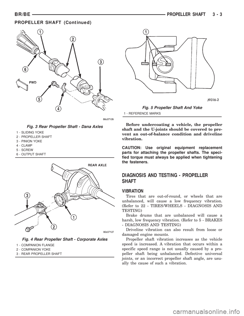
Fig. 3 Rear Propeller Shaft - Dana Axles
1 - SLIDING YOKE
2 - PROPELLER SHAFT
3 - PINION YOKE
4 - CLAMP
5 - SCREW
6 - OUTPUT SHAFT
Fig. 4 Rear Propeller Shaft - Corporate Axles
1 - COMPANION FLANGE
2 - COMPANION YOKE
3 - REAR PROPELLER SHAFT
Fig. 5 Propeller Shaft And Yoke
1 - REFERENCE MARKS
BR/BEPROPELLER SHAFT 3 - 3
PROPELLER SHAFT (Continued)
Page 77 of 2889
DRIVELINE VIBRATION
Drive Condition Possible Cause Correction
Propeller Shaft Noise 1) Undercoating or other foreign
material on shaft.1) Clean exterior of shaft and wash
with solvent.
2) Loose U-joint clamp screws. 2) Install new clamps and screws
and tighten to proper torque.
3) Loose or bent U-joint yoke or
excessive runout.3) Install new yoke.
4) Incorrect driveline angularity. 4) Measure and correct driveline
angles.
5) Rear spring center bolt not in
seat.5) Loosen spring u-bolts and seat
center bolt.
6) Worn U-joint bearings. 6) Install new U-joint.
7) Propeller shaft damaged or out
of balance.7) Installl new propeller shaft.
8) Broken rear spring. 8) Install new rear spring.
9) Excessive runout or unbalanced
condition.9) Re-index propeller shaft, test,
and evaluate.
10) Excessive drive pinion gear
shaft runout.10) Re-index propeller shaft and
evaluate.
11) Excessive axle yoke deflection. 11) Inspect and replace yoke if
necessary.
12) Excessive transfer case runout. 12) Inspect and repair as necessary.
Universal Joint Noise 1) Loose U-joint clamp screws. 1) Install new clamps and screws
and tighten to proper torque.
2) Lack of lubrication. 2) Replace as U-joints as
necessary.
BALANCE
NOTE: Removing and re-indexing the propeller
shaft 180É relative to the yoke may eliminate some
vibrations.
If propeller shaft is suspected of being unbalanced,
it can be verified with the following procedure:
(1) Raise the vehicle.
(2) Clean all the foreign material from the propel-
ler shaft and the universal joints.
(3) Inspect the propeller shaft for missing balance
weights, broken welds, and bent areas.If the pro-
peller shaft is bent, it must be replaced.
(4) Inspect the universal joints to ensure that they
are not worn, are properly installed, and are cor-
rectly aligned with the shaft.
(5) Check the universal joint clamp screws torque.
(6) Remove the wheels and tires. Install the wheel
lug nuts to retain the brake drums or rotors.
(7) Mark and number the shaft six inches from the
yoke end at four positions 90É apart.(8) Run and accelerate the vehicle until vibration
occurs. Note the intensity and speed the vibration
occurred. Stop the engine.
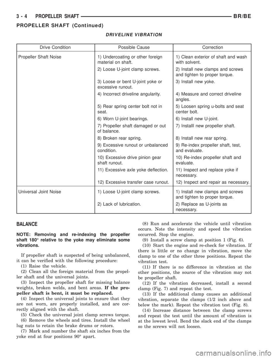
(9) Install a screw clamp at position 1 (Fig. 6).
(10) Start the engine and re-check for vibration. If
there is little or no change in vibration, move the
clamp to one of the other three positions. Repeat the
vibration test.
(11) If there is no difference in vibration at the
other positions, the source of the vibration may not
be propeller shaft.
(12) If the vibration decreased, install a second
clamp (Fig. 7) and repeat the test.
(13) If the additional clamp causes an additional
vibration, separate the clamps (1/2 inch above and
below the mark). Repeat the vibration test (Fig. 8).
(14) Increase distance between the clamp screws
and repeat the test until the amount of vibration is
at the lowest level. Bend the slack end of the clamps
so the screws will not loosen.
3 - 4 PROPELLER SHAFTBR/BE
PROPELLER SHAFT (Continued)
Page 86 of 2889
mate and side gears. The side gears are splined to
the axle shafts.
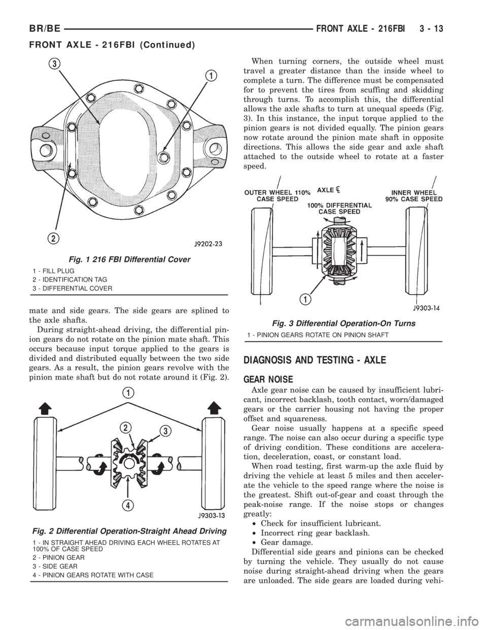
During straight-ahead driving, the differential pin-
ion gears do not rotate on the pinion mate shaft. This
occurs because input torque applied to the gears is
divided and distributed equally between the two side
gears. As a result, the pinion gears revolve with the
pinion mate shaft but do not rotate around it (Fig. 2).When turning corners, the outside wheel must
travel a greater distance than the inside wheel to
complete a turn. The difference must be compensated
for to prevent the tires from scuffing and skidding
through turns. To accomplish this, the differential
allows the axle shafts to turn at unequal speeds (Fig.
3). In this instance, the input torque applied to the
pinion gears is not divided equally. The pinion gears
now rotate around the pinion mate shaft in opposite
directions. This allows the side gear and axle shaft
attached to the outside wheel to rotate at a faster
speed.
DIAGNOSIS AND TESTING - AXLE
GEAR NOISE
Axle gear noise can be caused by insufficient lubri-
cant, incorrect backlash, tooth contact, worn/damaged
gears or the carrier housing not having the proper
offset and squareness.
Gear noise usually happens at a specific speed
range. The noise can also occur during a specific type
of driving condition. These conditions are accelera-
tion, deceleration, coast, or constant load.
When road testing, first warm-up the axle fluid by
driving the vehicle at least 5 miles and then acceler-
ate the vehicle to the speed range where the noise is
the greatest. Shift out-of-gear and coast through the
peak-noise range. If the noise stops or changes
greatly:
²Check for insufficient lubricant.
²Incorrect ring gear backlash.
²Gear damage.
Differential side gears and pinions can be checked
by turning the vehicle. They usually do not cause
noise during straight-ahead driving when the gears
are unloaded. The side gears are loaded during vehi-
Fig. 1 216 FBI Differential Cover
1 - FILL PLUG
2 - IDENTIFICATION TAG
3 - DIFFERENTIAL COVER
Fig. 2 Differential Operation-Straight Ahead Driving
1 - IN STRAIGHT AHEAD DRIVING EACH WHEEL ROTATES AT
100% OF CASE SPEED
2 - PINION GEAR
3 - SIDE GEAR
4 - PINION GEARS ROTATE WITH CASE
Fig. 3 Differential Operation-On Turns
1 - PINION GEARS ROTATE ON PINION SHAFT
BR/BEFRONT AXLE - 216FBI 3 - 13
FRONT AXLE - 216FBI (Continued)
Page 89 of 2889
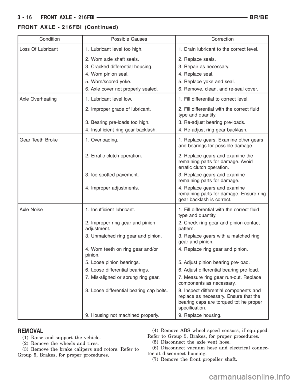
Condition Possible Causes Correction
Loss Of Lubricant 1. Lubricant level too high. 1. Drain lubricant to the correct level.
2. Worn axle shaft seals. 2. Replace seals.
3. Cracked differential housing. 3. Repair as necessary.
4. Worn pinion seal. 4. Replace seal.
5. Worn/scored yoke. 5. Replace yoke and seal.
6. Axle cover not properly sealed. 6. Remove, clean, and re-seal cover.
Axle Overheating 1. Lubricant level low. 1. Fill differential to correct level.
2. Improper grade of lubricant. 2. Fill differential with the correct fluid
type and quantity.
3. Bearing pre-loads too high. 3. Re-adjust bearing pre-loads.
4. Insufficient ring gear backlash. 4. Re-adjust ring gear backlash.
Gear Teeth Broke 1. Overloading. 1. Replace gears. Examine other gears
and bearings for possible damage.
2. Erratic clutch operation. 2. Replace gears and examine the
remaining parts for damage. Avoid
erratic clutch operation.
3. Ice-spotted pavement. 3. Replace gears and examine
remaining parts for damage.
4. Improper adjustments. 4. Replace gears and examine
remaining parts for damage. Ensure ring
gear backlash is correct.
Axle Noise 1. Insufficient lubricant. 1. Fill differential with the correct fluid
type and quantity.
2. Improper ring gear and pinion
adjustment.2. Check ring gear and pinion contact
pattern.
3. Unmatched ring gear and pinion. 3. Replace gears with a matched ring
gear and pinion.
4. Worn teeth on ring gear and/or
pinion.4. Replace ring gear and pinion.
5. Loose pinion bearings. 5. Adjust pinion bearing pre-load.
6. Loose differential bearings. 6. Adjust differential bearing pre-load.
7. Mis-aligned or sprung ring gear. 7. Measure ring gear run-out. Replace
components as necessary.
8. Loose differential bearing cap bolts. 8. Inspect differential components and
replace as necessary. Ensure that the
bearing caps are torqued tot he proper
specification.
9. Housing not machined properly. 9. Replace housing.
REMOVAL
(1) Raise and support the vehicle.
(2) Remove the wheels and tires.
(3) Remove the brake calipers and rotors. Refer to
Group 5, Brakes, for proper procedures.(4) Remove ABS wheel speed sensors, if equipped.
Refer to Group 5, Brakes, for proper procedures.
(5) Disconnect the axle vent hose.
(6) Disconnect vacuum hose and electrical connec-
tor at disconnect housing.
(7) Remove the front propeller shaft.
3 - 16 FRONT AXLE - 216FBIBR/BE
FRONT AXLE - 216FBI (Continued)
Page 90 of 2889
(8) Disconnect the stabilizer bar links at the axle
brackets.
(9) Disconnect the shock absorbers from axle
brackets.
(10) Disconnect the track bar from the axle
bracket.
(11) Disconnect the tie rod and drag link from the
steering knuckles.
(12) Position the axle with a suitable lifting device
under the axle assembly.
(13) Secure axle to lifting device.
(14) Mark suspension alignment cams for installa-
tion reference.
(15) Disconnect the upper and lower suspension
arms from the axle bracket.
(16) Lower the axle. The coil springs will drop
with the axle.
(17) Remove the coil springs from the axle bracket.
INSTALLATION
CAUTION: Suspension components with rubber
bushings should be tightened with the weight of the
vehicle on the suspension, at normal height. If
springs are not at their normal ride position, vehicle
ride comfort could be affected and premature bush-
ing wear may occur. Rubber bushings must never
be lubricated.
(1) Support the axle on a suitable lifting device.
(2) Secure axle to lifting device.
(3) Position the axle under the vehicle.
(4) Install the springs, retainer clip and bolts.
(5) Raise the axle and align it with the spring
pads.
(6) Position the upper and lower suspension arms
in the axle brackets. Install bolts, nuts and align the
suspension alignment cams to the reference marks.
Do not tighten at this time.
(7) Connect the track bar to the axle bracket and
install the bolt. Do not tighten at this time.
(8) Install the shock absorber and tighten bolts to
121 N´m (89 ft. lbs.) torque.
(9) Install the stabilizer bar link to the axle
bracket. Tighten the nut to 37 N´m (27 ft. lbs.)
torque.
(10) Install the drag link and tie rod to the steer-
ing knuckles and tighten the nuts to 88 N´m (65 ft.
lbs.) torque.
(11) Install the ABS wheel speed sensors, if
equipped. Refer to group 5, Brakes, for proper proce-
dures.
(12) Install the brake calipers and rotors. Refer to
Group 5, Brakes, for proper procedures.
(13) Connect the vent hose to the tube fitting.
(14) Connect vacuum hose and electrical connector
to disconnect housing.(15) Install front propeller shaft.
(16) Check and add differential lubricant, if neces-
sary. Refer to Lubricant Specifications in this section
for lubricant requirements.
(17) Install the wheel and tire assemblies.
(18) Remove the supports and lower the vehicle.
(19) Tighten the upper suspension arm nuts at
axle to 121 N´m (89 ft. lbs.) torque. Tighten the
upper suspension arm nuts at frame to 84 N´m (62 ft.
lbs.) torque.
(20) Tighten the lower suspension arm nuts at
axle to 84 N´m (62 ft. lbs.) torque. Tighten the lower
suspension arm nuts at frame to 119 N´m (88 ft. lbs.)
torque.
(21) Tighten the track bar bolt at the axle bracket
to 176 N´m (130 ft. lbs.) torque.
(22) Check the front wheel alignment.
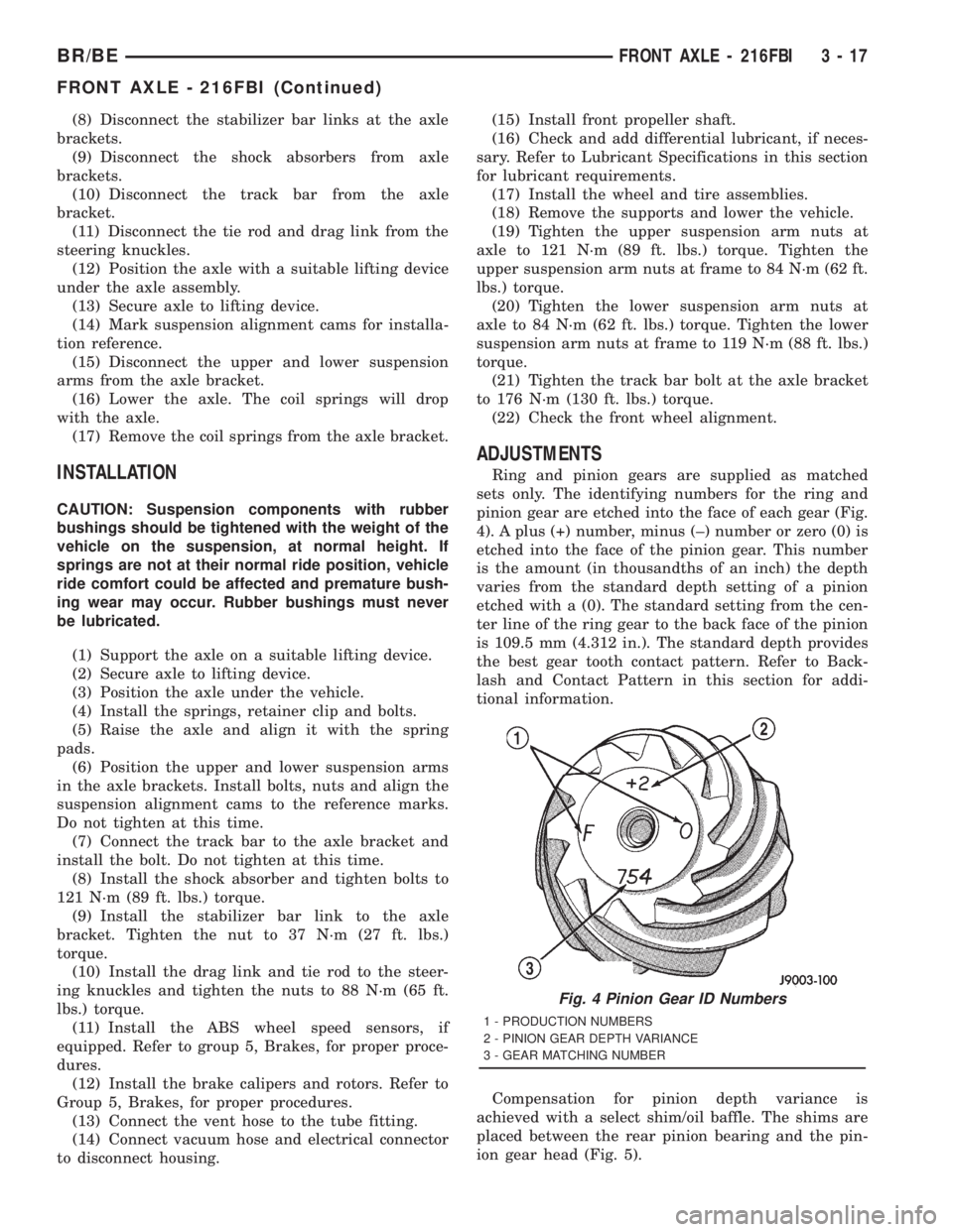
ADJUSTMENTS
Ring and pinion gears are supplied as matched
sets only. The identifying numbers for the ring and
pinion gear are etched into the face of each gear (Fig.
4). A plus (+) number, minus (±) number or zero (0) is
etched into the face of the pinion gear. This number
is the amount (in thousandths of an inch) the depth
varies from the standard depth setting of a pinion
etched with a (0). The standard setting from the cen-
ter line of the ring gear to the back face of the pinion
is 109.5 mm (4.312 in.). The standard depth provides
the best gear tooth contact pattern. Refer to Back-
lash and Contact Pattern in this section for addi-
tional information.
Compensation for pinion depth variance is
achieved with a select shim/oil baffle. The shims are
placed between the rear pinion bearing and the pin-
ion gear head (Fig. 5).
Fig. 4 Pinion Gear ID Numbers
1 - PRODUCTION NUMBERS
2 - PINION GEAR DEPTH VARIANCE
3 - GEAR MATCHING NUMBER
BR/BEFRONT AXLE - 216FBI 3 - 17
FRONT AXLE - 216FBI (Continued)
Page 98 of 2889
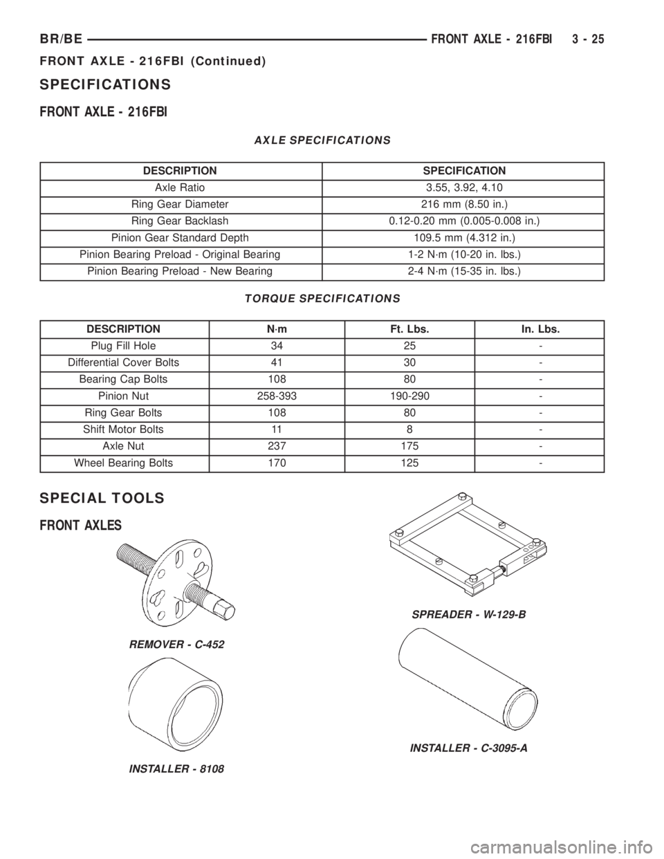
SPECIFICATIONS
FRONT AXLE - 216FBI
AXLE SPECIFICATIONS
DESCRIPTION SPECIFICATION
Axle Ratio 3.55, 3.92, 4.10
Ring Gear Diameter 216 mm (8.50 in.)
Ring Gear Backlash 0.12-0.20 mm (0.005-0.008 in.)
Pinion Gear Standard Depth 109.5 mm (4.312 in.)
Pinion Bearing Preload - Original Bearing 1-2 N´m (10-20 in. lbs.)
Pinion Bearing Preload - New Bearing 2-4 N´m (15-35 in. lbs.)
TORQUE SPECIFICATIONS
DESCRIPTION N´m Ft. Lbs. In. Lbs.
Plug Fill Hole 34 25 -
Differential Cover Bolts 41 30 -
Bearing Cap Bolts 108 80 -
Pinion Nut 258-393 190-290 -
Ring Gear Bolts 108 80 -
Shift Motor Bolts 11 8 -
Axle Nut 237 175 -
Wheel Bearing Bolts 170 125 -
SPECIAL TOOLS
FRONT AXLES
REMOVER - C-452
INSTALLER - 8108
SPREADER - W-129-B
INSTALLER - C-3095-A
BR/BEFRONT AXLE - 216FBI 3 - 25
FRONT AXLE - 216FBI (Continued)