2001 DODGE RAM set clock
[x] Cancel search: set clockPage 92 of 2889
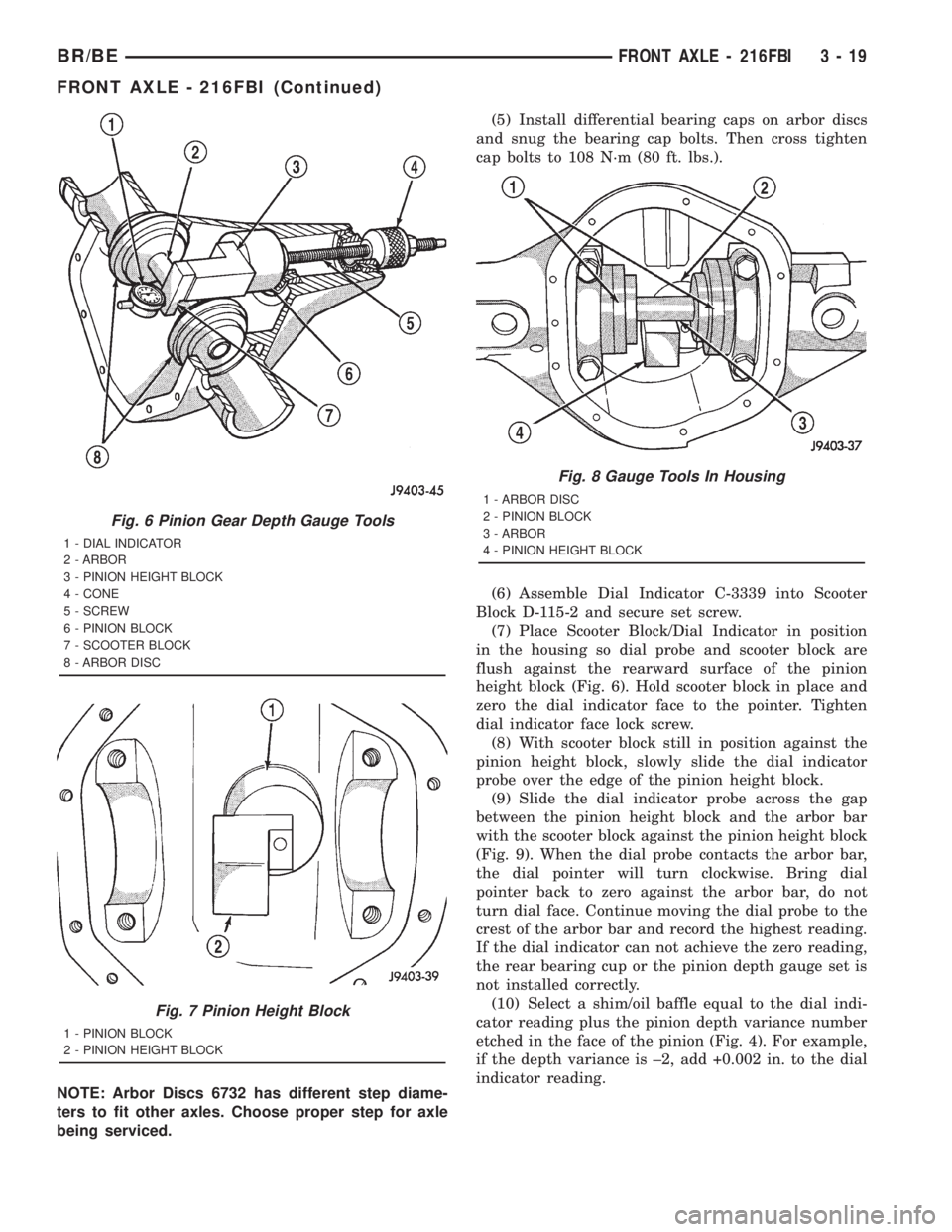
NOTE: Arbor Discs 6732 has different step diame-
ters to fit other axles. Choose proper step for axle
being serviced.(5) Install differential bearing caps on arbor discs
and snug the bearing cap bolts. Then cross tighten
cap bolts to 108 N´m (80 ft. lbs.).
(6) Assemble Dial Indicator C-3339 into Scooter
Block D-115-2 and secure set screw.
(7) Place Scooter Block/Dial Indicator in position
in the housing so dial probe and scooter block are
flush against the rearward surface of the pinion
height block (Fig. 6). Hold scooter block in place and
zero the dial indicator face to the pointer. Tighten
dial indicator face lock screw.
(8) With scooter block still in position against the
pinion height block, slowly slide the dial indicator
probe over the edge of the pinion height block.
(9) Slide the dial indicator probe across the gap
between the pinion height block and the arbor bar
with the scooter block against the pinion height block
(Fig. 9). When the dial probe contacts the arbor bar,
the dial pointer will turn clockwise. Bring dial
pointer back to zero against the arbor bar, do not
turn dial face. Continue moving the dial probe to the
crest of the arbor bar and record the highest reading.
If the dial indicator can not achieve the zero reading,
the rear bearing cup or the pinion depth gauge set is
not installed correctly.
(10) Select a shim/oil baffle equal to the dial indi-
cator reading plus the pinion depth variance number
etched in the face of the pinion (Fig. 4). For example,
if the depth variance is ±2, add +0.002 in. to the dial
indicator reading.
Fig. 6 Pinion Gear Depth Gauge Tools
1 - DIAL INDICATOR
2 - ARBOR
3 - PINION HEIGHT BLOCK
4 - CONE
5 - SCREW
6 - PINION BLOCK
7 - SCOOTER BLOCK
8 - ARBOR DISC
Fig. 7 Pinion Height Block
1 - PINION BLOCK
2 - PINION HEIGHT BLOCK
Fig. 8 Gauge Tools In Housing
1 - ARBOR DISC
2 - PINION BLOCK
3 - ARBOR
4 - PINION HEIGHT BLOCK
BR/BEFRONT AXLE - 216FBI 3 - 19
FRONT AXLE - 216FBI (Continued)
Page 125 of 2889
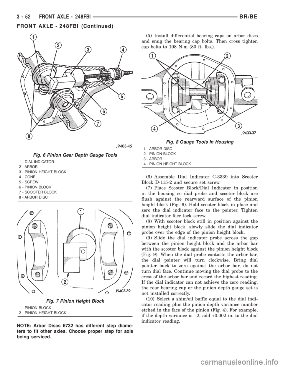
NOTE: Arbor Discs 6732 has different step diame-
ters to fit other axles. Choose proper step for axle
being serviced.(5) Install differential bearing caps on arbor discs
and snug the bearing cap bolts. Then cross tighten
cap bolts to 108 N´m (80 ft. lbs.).
(6) Assemble Dial Indicator C-3339 into Scooter
Block D-115-2 and secure set screw.
(7) Place Scooter Block/Dial Indicator in position
in the housing so dial probe and scooter block are
flush against the rearward surface of the pinion
height block (Fig. 6). Hold scooter block in place and
zero the dial indicator face to the pointer. Tighten
dial indicator face lock screw.
(8) With scooter block still in position against the
pinion height block, slowly slide the dial indicator
probe over the edge of the pinion height block.
(9) Slide the dial indicator probe across the gap
between the pinion height block and the arbor bar
with the scooter block against the pinion height block
(Fig. 9). When the dial probe contacts the arbor bar,
the dial pointer will turn clockwise. Bring dial
pointer back to zero against the arbor bar, do not
turn dial face. Continue moving the dial probe to the
crest of the arbor bar and record the highest reading.
If the dial indicator can not achieve the zero reading,
the rear bearing cup or the pinion depth gauge set is
not installed correctly.
(10) Select a shim/oil baffle equal to the dial indi-
cator reading plus the pinion depth variance number
etched in the face of the pinion (Fig. 4). For example,
if the depth variance is ±2, add +0.002 in. to the dial
indicator reading.
Fig. 6 Pinion Gear Depth Gauge Tools
1 - DIAL INDICATOR
2 - ARBOR
3 - PINION HEIGHT BLOCK
4 - CONE
5 - SCREW
6 - PINION BLOCK
7 - SCOOTER BLOCK
8 - ARBOR DISC
Fig. 7 Pinion Height Block
1 - PINION BLOCK
2 - PINION HEIGHT BLOCK
Fig. 8 Gauge Tools In Housing
1 - ARBOR DISC
2 - PINION BLOCK
3 - ARBOR
4 - PINION HEIGHT BLOCK
3 - 52 FRONT AXLE - 248FBIBR/BE
FRONT AXLE - 248FBI (Continued)
Page 159 of 2889
(5) Assemble Dial Indicator C-3339 into Scooter
Block D-115-2 and secure set screw.
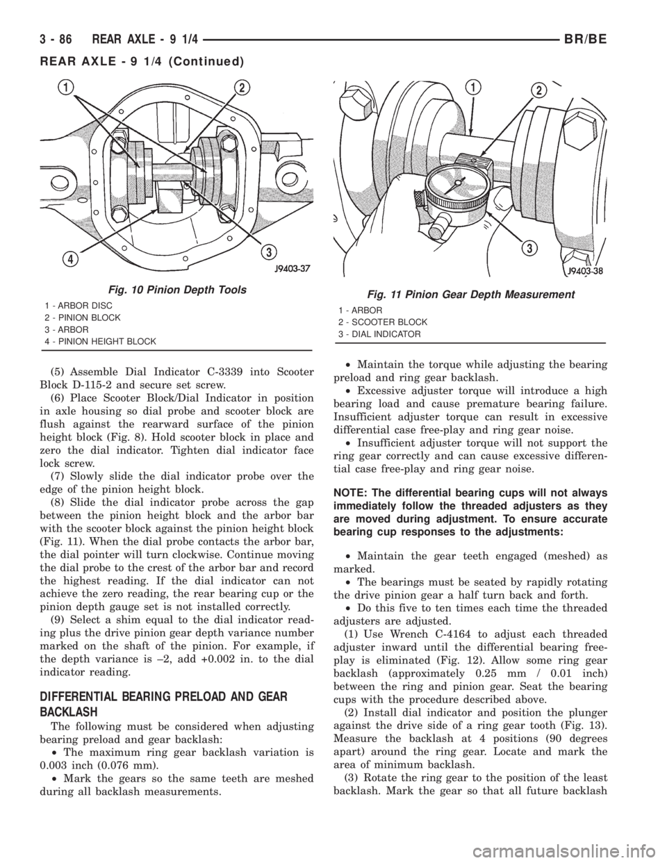
(6) Place Scooter Block/Dial Indicator in position
in axle housing so dial probe and scooter block are
flush against the rearward surface of the pinion
height block (Fig. 8). Hold scooter block in place and
zero the dial indicator. Tighten dial indicator face
lock screw.
(7) Slowly slide the dial indicator probe over the
edge of the pinion height block.
(8) Slide the dial indicator probe across the gap
between the pinion height block and the arbor bar
with the scooter block against the pinion height block
(Fig. 11). When the dial probe contacts the arbor bar,
the dial pointer will turn clockwise. Continue moving
the dial probe to the crest of the arbor bar and record
the highest reading. If the dial indicator can not
achieve the zero reading, the rear bearing cup or the
pinion depth gauge set is not installed correctly.
(9) Select a shim equal to the dial indicator read-
ing plus the drive pinion gear depth variance number
marked on the shaft of the pinion. For example, if
the depth variance is ±2, add +0.002 in. to the dial
indicator reading.
DIFFERENTIAL BEARING PRELOAD AND GEAR
BACKLASH
The following must be considered when adjusting
bearing preload and gear backlash:
²The maximum ring gear backlash variation is
0.003 inch (0.076 mm).
²Mark the gears so the same teeth are meshed
during all backlash measurements.²Maintain the torque while adjusting the bearing
preload and ring gear backlash.
²Excessive adjuster torque will introduce a high
bearing load and cause premature bearing failure.
Insufficient adjuster torque can result in excessive
differential case free-play and ring gear noise.
²Insufficient adjuster torque will not support the
ring gear correctly and can cause excessive differen-
tial case free-play and ring gear noise.
NOTE: The differential bearing cups will not always
immediately follow the threaded adjusters as they
are moved during adjustment. To ensure accurate
bearing cup responses to the adjustments:
²Maintain the gear teeth engaged (meshed) as
marked.
²The bearings must be seated by rapidly rotating
the drive pinion gear a half turn back and forth.
²Do this five to ten times each time the threaded
adjusters are adjusted.
(1) Use Wrench C-4164 to adjust each threaded
adjuster inward until the differential bearing free-
play is eliminated (Fig. 12). Allow some ring gear
backlash (approximately 0.25 mm / 0.01 inch)
between the ring and pinion gear. Seat the bearing
cups with the procedure described above.
(2) Install dial indicator and position the plunger
against the drive side of a ring gear tooth (Fig. 13).
Measure the backlash at 4 positions (90 degrees
apart) around the ring gear. Locate and mark the
area of minimum backlash.
(3) Rotate the ring gear to the position of the least
backlash. Mark the gear so that all future backlash
Fig. 10 Pinion Depth Tools
1 - ARBOR DISC
2 - PINION BLOCK
3 - ARBOR
4 - PINION HEIGHT BLOCKFig. 11 Pinion Gear Depth Measurement
1 - ARBOR
2 - SCOOTER BLOCK
3 - DIAL INDICATOR
3 - 86 REAR AXLE-91/4BR/BE
REAR AXLE - 9 1/4 (Continued)
Page 189 of 2889
(5) Install differential bearing caps on arbor discs
and snug the bearing cap bolts. Then cross tighten
cap bolts to 108 N´m (80 ft. lbs.).
(6) Assemble Dial Indicator C-3339 into Scooter
Block D-115-2 and secure set screw.
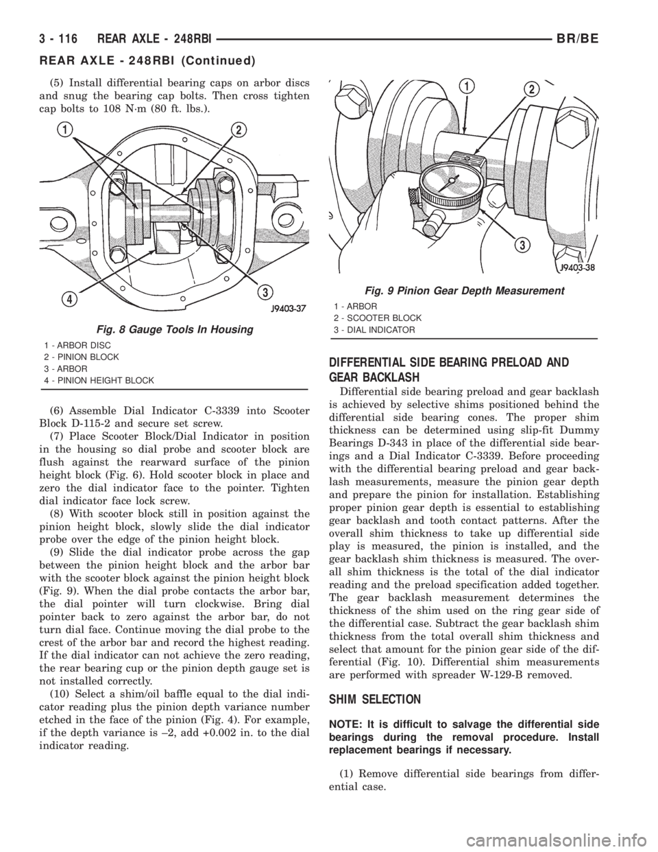
(7) Place Scooter Block/Dial Indicator in position
in the housing so dial probe and scooter block are
flush against the rearward surface of the pinion
height block (Fig. 6). Hold scooter block in place and
zero the dial indicator face to the pointer. Tighten
dial indicator face lock screw.
(8) With scooter block still in position against the
pinion height block, slowly slide the dial indicator
probe over the edge of the pinion height block.
(9) Slide the dial indicator probe across the gap
between the pinion height block and the arbor bar
with the scooter block against the pinion height block
(Fig. 9). When the dial probe contacts the arbor bar,
the dial pointer will turn clockwise. Bring dial
pointer back to zero against the arbor bar, do not
turn dial face. Continue moving the dial probe to the
crest of the arbor bar and record the highest reading.
If the dial indicator can not achieve the zero reading,
the rear bearing cup or the pinion depth gauge set is
not installed correctly.
(10) Select a shim/oil baffle equal to the dial indi-
cator reading plus the pinion depth variance number
etched in the face of the pinion (Fig. 4). For example,
if the depth variance is ±2, add +0.002 in. to the dial
indicator reading.
DIFFERENTIAL SIDE BEARING PRELOAD AND
GEAR BACKLASH
Differential side bearing preload and gear backlash
is achieved by selective shims positioned behind the
differential side bearing cones. The proper shim
thickness can be determined using slip-fit Dummy
Bearings D-343 in place of the differential side bear-
ings and a Dial Indicator C-3339. Before proceeding
with the differential bearing preload and gear back-
lash measurements, measure the pinion gear depth
and prepare the pinion for installation. Establishing
proper pinion gear depth is essential to establishing
gear backlash and tooth contact patterns. After the
overall shim thickness to take up differential side
play is measured, the pinion is installed, and the
gear backlash shim thickness is measured. The over-
all shim thickness is the total of the dial indicator
reading and the preload specification added together.
The gear backlash measurement determines the
thickness of the shim used on the ring gear side of
the differential case. Subtract the gear backlash shim
thickness from the total overall shim thickness and
select that amount for the pinion gear side of the dif-
ferential (Fig. 10). Differential shim measurements
are performed with spreader W-129-B removed.
SHIM SELECTION
NOTE: It is difficult to salvage the differential side
bearings during the removal procedure. Install
replacement bearings if necessary.
(1) Remove differential side bearings from differ-
ential case.
Fig. 8 Gauge Tools In Housing
1 - ARBOR DISC
2 - PINION BLOCK
3 - ARBOR
4 - PINION HEIGHT BLOCK
Fig. 9 Pinion Gear Depth Measurement
1 - ARBOR
2 - SCOOTER BLOCK
3 - DIAL INDICATOR
3 - 116 REAR AXLE - 248RBIBR/BE
REAR AXLE - 248RBI (Continued)
Page 220 of 2889
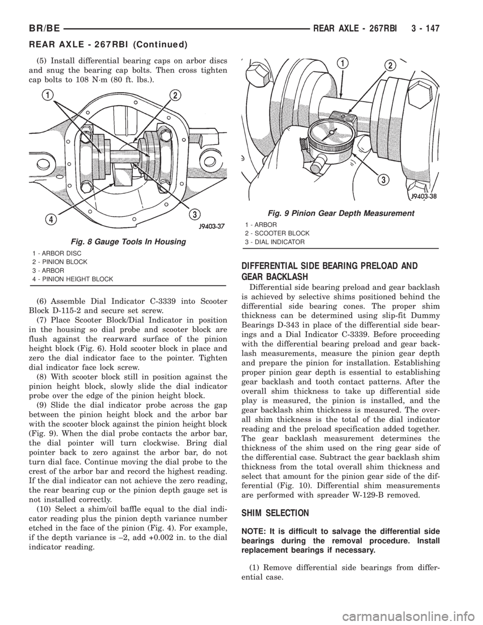
(5) Install differential bearing caps on arbor discs
and snug the bearing cap bolts. Then cross tighten
cap bolts to 108 N´m (80 ft. lbs.).
(6) Assemble Dial Indicator C-3339 into Scooter
Block D-115-2 and secure set screw.
(7) Place Scooter Block/Dial Indicator in position
in the housing so dial probe and scooter block are
flush against the rearward surface of the pinion
height block (Fig. 6). Hold scooter block in place and
zero the dial indicator face to the pointer. Tighten
dial indicator face lock screw.
(8) With scooter block still in position against the
pinion height block, slowly slide the dial indicator
probe over the edge of the pinion height block.
(9) Slide the dial indicator probe across the gap
between the pinion height block and the arbor bar
with the scooter block against the pinion height block
(Fig. 9). When the dial probe contacts the arbor bar,
the dial pointer will turn clockwise. Bring dial
pointer back to zero against the arbor bar, do not
turn dial face. Continue moving the dial probe to the
crest of the arbor bar and record the highest reading.
If the dial indicator can not achieve the zero reading,
the rear bearing cup or the pinion depth gauge set is
not installed correctly.
(10) Select a shim/oil baffle equal to the dial indi-
cator reading plus the pinion depth variance number
etched in the face of the pinion (Fig. 4). For example,
if the depth variance is ±2, add +0.002 in. to the dial
indicator reading.
DIFFERENTIAL SIDE BEARING PRELOAD AND
GEAR BACKLASH
Differential side bearing preload and gear backlash
is achieved by selective shims positioned behind the
differential side bearing cones. The proper shim
thickness can be determined using slip-fit Dummy
Bearings D-343 in place of the differential side bear-
ings and a Dial Indicator C-3339. Before proceeding
with the differential bearing preload and gear back-
lash measurements, measure the pinion gear depth
and prepare the pinion for installation. Establishing
proper pinion gear depth is essential to establishing
gear backlash and tooth contact patterns. After the
overall shim thickness to take up differential side
play is measured, the pinion is installed, and the
gear backlash shim thickness is measured. The over-
all shim thickness is the total of the dial indicator
reading and the preload specification added together.
The gear backlash measurement determines the
thickness of the shim used on the ring gear side of
the differential case. Subtract the gear backlash shim
thickness from the total overall shim thickness and
select that amount for the pinion gear side of the dif-
ferential (Fig. 10). Differential shim measurements
are performed with spreader W-129-B removed.
SHIM SELECTION
NOTE: It is difficult to salvage the differential side
bearings during the removal procedure. Install
replacement bearings if necessary.
(1) Remove differential side bearings from differ-
ential case.
Fig. 8 Gauge Tools In Housing
1 - ARBOR DISC
2 - PINION BLOCK
3 - ARBOR
4 - PINION HEIGHT BLOCK
Fig. 9 Pinion Gear Depth Measurement
1 - ARBOR
2 - SCOOTER BLOCK
3 - DIAL INDICATOR
BR/BEREAR AXLE - 267RBI 3 - 147
REAR AXLE - 267RBI (Continued)
Page 249 of 2889
(5) Assemble Dial Indicator C-3339 into Scooter
Block D-115-2 and secure set screw.
(6) Place Scooter Block/Dial Indicator in position
in the housing so dial probe and scooter block are
flush against the surface of the pinion height block.
Hold scooter block in place and zero the dial indica-
tor face to the pointer. Tighten dial indicator face
lock screw.
(7) With scooter block still in position against the
pinion height block, slowly slide the dial indicator
probe over the edge of the pinion height block.
Observe how many revolutions counterclockwise the
dial pointer travels (approximately 0.125 in.) to the
out-stop of the dial indicator.
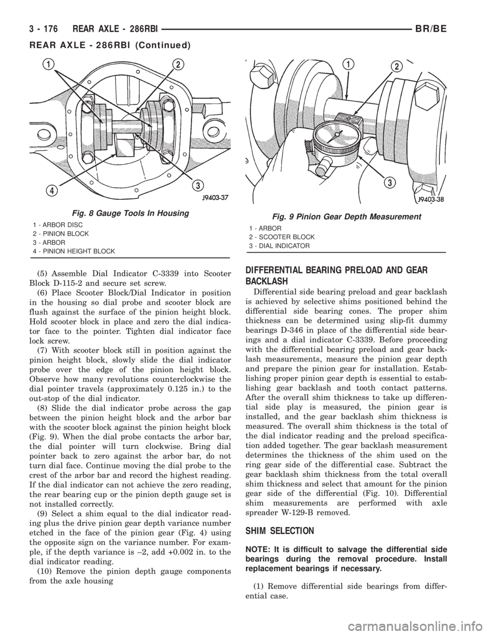
(8) Slide the dial indicator probe across the gap
between the pinion height block and the arbor bar
with the scooter block against the pinion height block
(Fig. 9). When the dial probe contacts the arbor bar,
the dial pointer will turn clockwise. Bring dial
pointer back to zero against the arbor bar, do not
turn dial face. Continue moving the dial probe to the
crest of the arbor bar and record the highest reading.
If the dial indicator can not achieve the zero reading,
the rear bearing cup or the pinion depth gauge set is
not installed correctly.
(9) Select a shim equal to the dial indicator read-
ing plus the drive pinion gear depth variance number
etched in the face of the pinion gear (Fig. 4) using
the opposite sign on the variance number. For exam-
ple, if the depth variance is ±2, add +0.002 in. to the
dial indicator reading.
(10) Remove the pinion depth gauge components
from the axle housingDIFFERENTIAL BEARING PRELOAD AND GEAR
BACKLASH
Differential side bearing preload and gear backlash
is achieved by selective shims positioned behind the
differential side bearing cones. The proper shim
thickness can be determined using slip-fit dummy
bearings D-346 in place of the differential side bear-
ings and a dial indicator C-3339. Before proceeding
with the differential bearing preload and gear back-
lash measurements, measure the pinion gear depth
and prepare the pinion gear for installation. Estab-
lishing proper pinion gear depth is essential to estab-
lishing gear backlash and tooth contact patterns.
After the overall shim thickness to take up differen-
tial side play is measured, the pinion gear is
installed, and the gear backlash shim thickness is
measured. The overall shim thickness is the total of
the dial indicator reading and the preload specifica-
tion added together. The gear backlash measurement
determines the thickness of the shim used on the
ring gear side of the differential case. Subtract the
gear backlash shim thickness from the total overall
shim thickness and select that amount for the pinion
gear side of the differential (Fig. 10). Differential
shim measurements are performed with axle
spreader W-129-B removed.
SHIM SELECTION
NOTE: It is difficult to salvage the differential side
bearings during the removal procedure. Install
replacement bearings if necessary.
(1) Remove differential side bearings from differ-
ential case.
Fig. 8 Gauge Tools In Housing
1 - ARBOR DISC
2 - PINION BLOCK
3 - ARBOR
4 - PINION HEIGHT BLOCKFig. 9 Pinion Gear Depth Measurement
1 - ARBOR
2 - SCOOTER BLOCK
3 - DIAL INDICATOR
3 - 176 REAR AXLE - 286RBIBR/BE
REAR AXLE - 286RBI (Continued)
Page 325 of 2889
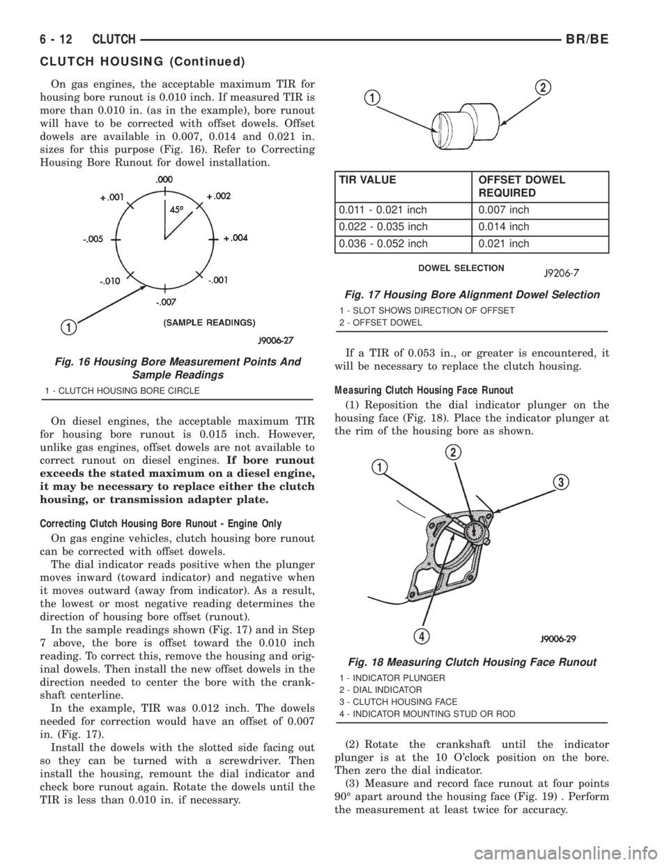
On gas engines, the acceptable maximum TIR for
housing bore runout is 0.010 inch. If measured TIR is
more than 0.010 in. (as in the example), bore runout
will have to be corrected with offset dowels. Offset
dowels are available in 0.007, 0.014 and 0.021 in.
sizes for this purpose (Fig. 16). Refer to Correcting
Housing Bore Runout for dowel installation.
On diesel engines, the acceptable maximum TIR
for housing bore runout is 0.015 inch. However,
unlike gas engines, offset dowels are not available to
correct runout on diesel engines.If bore runout
exceeds the stated maximum on a diesel engine,
it may be necessary to replace either the clutch
housing, or transmission adapter plate.
Correcting Clutch Housing Bore Runout - Engine Only
On gas engine vehicles, clutch housing bore runout
can be corrected with offset dowels.
The dial indicator reads positive when the plunger
moves inward (toward indicator) and negative when
it moves outward (away from indicator). As a result,
the lowest or most negative reading determines the
direction of housing bore offset (runout).
In the sample readings shown (Fig. 17) and in Step
7 above, the bore is offset toward the 0.010 inch
reading. To correct this, remove the housing and orig-
inal dowels. Then install the new offset dowels in the
direction needed to center the bore with the crank-
shaft centerline.
In the example, TIR was 0.012 inch. The dowels
needed for correction would have an offset of 0.007
in. (Fig. 17).
Install the dowels with the slotted side facing out
so they can be turned with a screwdriver. Then
install the housing, remount the dial indicator and
check bore runout again. Rotate the dowels until the
TIR is less than 0.010 in. if necessary.If a TIR of 0.053 in., or greater is encountered, it
will be necessary to replace the clutch housing.
Measuring Clutch Housing Face Runout
(1) Reposition the dial indicator plunger on the
housing face (Fig. 18). Place the indicator plunger at
the rim of the housing bore as shown.
(2) Rotate the crankshaft until the indicator
plunger is at the 10 O'clock position on the bore.
Then zero the dial indicator.
(3) Measure and record face runout at four points
90É apart around the housing face (Fig. 19) . Perform
the measurement at least twice for accuracy.
Fig. 16 Housing Bore Measurement Points And
Sample Readings
1 - CLUTCH HOUSING BORE CIRCLE
Fig. 17 Housing Bore Alignment Dowel Selection
1 - SLOT SHOWS DIRECTION OF OFFSET
2 - OFFSET DOWEL
TIR VALUE OFFSET DOWEL
REQUIRED
0.011 - 0.021 inch 0.007 inch
0.022 - 0.035 inch 0.014 inch
0.036 - 0.052 inch 0.021 inch
Fig. 18 Measuring Clutch Housing Face Runout
1 - INDICATOR PLUNGER
2 - DIAL INDICATOR
3 - CLUTCH HOUSING FACE
4 - INDICATOR MOUNTING STUD OR ROD
6 - 12 CLUTCHBR/BE
CLUTCH HOUSING (Continued)
Page 377 of 2889
COOLANT RECOVERY
CONTAINER - 8.0L
DESCRIPTION
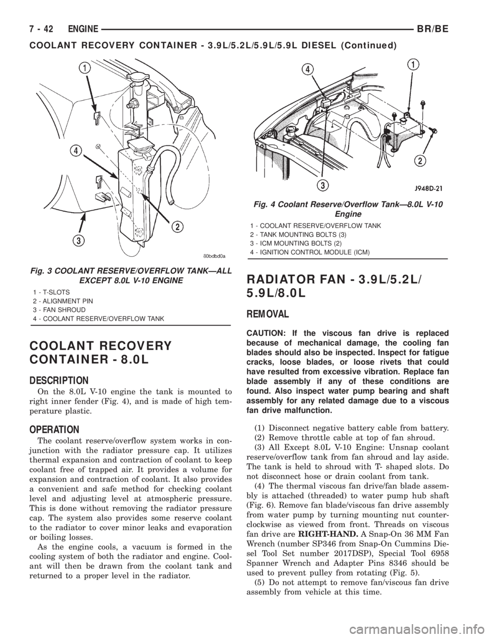
On the 8.0L V-10 engine the tank is mounted to
right inner fender (Fig. 4), and is made of high tem-
perature plastic.
OPERATION
The coolant reserve/overflow system works in con-
junction with the radiator pressure cap. It utilizes
thermal expansion and contraction of coolant to keep
coolant free of trapped air. It provides a volume for
expansion and contraction of coolant. It also provides
a convenient and safe method for checking coolant
level and adjusting level at atmospheric pressure.
This is done without removing the radiator pressure
cap. The system also provides some reserve coolant
to the radiator to cover minor leaks and evaporation
or boiling losses.
As the engine cools, a vacuum is formed in the
cooling system of both the radiator and engine. Cool-
ant will then be drawn from the coolant tank and
returned to a proper level in the radiator.
RADIATOR FAN - 3.9L/5.2L/
5.9L/8.0L
REMOVAL
CAUTION: If the viscous fan drive is replaced
because of mechanical damage, the cooling fan
blades should also be inspected. Inspect for fatigue
cracks, loose blades, or loose rivets that could
have resulted from excessive vibration. Replace fan
blade assembly if any of these conditions are
found. Also inspect water pump bearing and shaft
assembly for any related damage due to a viscous
fan drive malfunction.
(1) Disconnect negative battery cable from battery.
(2) Remove throttle cable at top of fan shroud.
(3) All Except 8.0L V-10 Engine: Unsnap coolant
reserve/overflow tank from fan shroud and lay aside.
The tank is held to shroud with T- shaped slots. Do
not disconnect hose or drain coolant from tank.
(4) The thermal viscous fan drive/fan blade assem-
bly is attached (threaded) to water pump hub shaft
(Fig. 6). Remove fan blade/viscous fan drive assembly
from water pump by turning mounting nut counter-
clockwise as viewed from front. Threads on viscous
fan drive areRIGHT-HAND.A Snap-On 36 MM Fan
Wrench (number SP346 from Snap-On Cummins Die-
sel Tool Set number 2017DSP), Special Tool 6958
Spanner Wrench and Adapter Pins 8346 should be
used to prevent pulley from rotating (Fig. 5).
(5) Do not attempt to remove fan/viscous fan drive
assembly from vehicle at this time.
Fig. 3 COOLANT RESERVE/OVERFLOW TANKÐALL
EXCEPT 8.0L V-10 ENGINE
1 - T-SLOTS
2 - ALIGNMENT PIN
3 - FAN SHROUD
4 - COOLANT RESERVE/OVERFLOW TANK
Fig. 4 Coolant Reserve/Overflow TankÐ8.0L V-10
Engine
1 - COOLANT RESERVE/OVERFLOW TANK
2 - TANK MOUNTING BOLTS (3)
3 - ICM MOUNTING BOLTS (2)
4 - IGNITION CONTROL MODULE (ICM)
7 - 42 ENGINEBR/BE
COOLANT RECOVERY CONTAINER - 3.9L/5.2L/5.9L/5.9L DIESEL (Continued)