2001 DODGE RAM jump cable
[x] Cancel search: jump cablePage 40 of 2889
JUMP STARTING
STANDARD PROCEDURE
WARNING: REVIEW ALL SAFETY PRECAUTIONS
AND WARNINGS IN GROUP 8A, BATTERY/START-
ING/CHARGING SYSTEMS DIAGNOSTICS. DO NOT
JUMP START A FROZEN BATTERY, PERSONAL
INJURY CAN RESULT. DO NOT JUMP START WHEN
MAINTENANCE FREE BATTERY INDICATOR DOT IS
YELLOW OR BRIGHT COLOR. DO NOT JUMP
START A VEHICLE WHEN THE BATTERY FLUID IS
BELOW THE TOP OF LEAD PLATES. DO NOT
ALLOW JUMPER CABLE CLAMPS TO TOUCH
EACH OTHER WHEN CONNECTED TO A BOOSTER
SOURCE. DO NOT USE OPEN FLAME NEAR BAT-
TERY. REMOVE METALLIC JEWELRY WORN ON
HANDS OR WRISTS TO AVOID INJURY BY ACCI-
DENTAL ARCING OF BATTERY CURRENT. WHEN
USING A HIGH OUTPUT BOOSTING DEVICE, DO
NOT ALLOW BATTERY VOLTAGE TO EXCEED 16
VOLTS. REFER TO INSTRUCTIONS PROVIDED
WITH DEVICE BEING USED.
CAUTION: When using another vehicle as a
booster, do not allow vehicles to touch. Electrical
systems can be damaged on either vehicle.
TO JUMP START A DISABLED VEHICLE:
(1) Raise hood on disabled vehicle and visually
inspect engine compartment for:
²Battery cable clamp condition, clean if necessary.
²Frozen battery.
²Yellow or bright color test indicator, if equipped.
²Low battery fluid level.
²Generator drive belt condition and tension.
²Fuel fumes or leakage, correct if necessary.
CAUTION: If the cause of starting problem on dis-
abled vehicle is severe, damage to booster vehicle
charging system can result.
(2) When using another vehicle as a booster
source, park the booster vehicle within cable reach.
Turn off all accessories, set the parking brake, place
the automatic transmission in PARK or the manual
transmission in NEUTRAL and turn the ignition
OFF.(3) On disabled vehicle, place gear selector in park
or neutral and set park brake. Turn off all accesso-
ries.
(4) Connect jumper cables to booster battery. RED
clamp to positive terminal (+). BLACK clamp to neg-
ative terminal (-). DO NOT allow clamps at opposite
end of cables to touch, electrical arc will result.
Review all warnings in this procedure.
(5) On disabled vehicle, connect RED jumper cable
clamp to positive (+) terminal. Connect BLACK
jumper cable clamp to engine ground as close to the
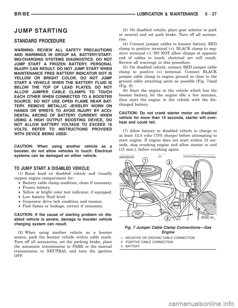
ground cable attaching point as possible (Fig. 7)and
(Fig. 8).
(6) Start the engine in the vehicle which has the
booster battery, let the engine idle a few minutes,
then start the engine in the vehicle with the dis-
charged battery.
CAUTION: Do not crank starter motor on disabled
vehicle for more than 15 seconds, starter will over-
heat and could fail.
(7) Allow battery in disabled vehicle to charge to
at least 12.4 volts (75% charge) before attempting to
start engine. If engine does not start within 15 sec-
onds, stop cranking engine and allow starter to cool
(15 min.), before cranking again.
Fig. 7 Jumper Cable Clamp ConnectionsÐGas
Engine
1 - NEGATIVE OR GROUND CABLE CONNECTION
2 - POSITIVE CABLE CONNECTION
3 - BATTERY
BR/BELUBRICATION & MAINTENANCE 0 - 27
Page 41 of 2889

DISCONNECT CABLE CLAMPS AS FOLLOWS:
²Disconnect BLACK cable clamp from engine
ground on disabled vehicle.
²When using a Booster vehicle, disconnect
BLACK cable clamp from battery negative terminal.
Disconnect RED cable clamp from battery positive
terminal.
²Disconnect RED cable clamp from battery posi-
tive terminal on disabled vehicle.
HOISTING
STANDARD PROCEDURE
Refer to the Owner's Manual for emergency vehicle
lifting procedures.
WARNING: THE HOISTING AND JACK LIFTING
POINTS PROVIDED ARE FOR A COMPLETE VEHI-
CLE. WHEN A CHASSIS OR DRIVETRAIN COMPO-
NENT IS REMOVED FROM A VEHICLE, THE
CENTER OF GRAVITY IS ALTERED MAKING SOME
HOISTING CONDITIONS UNSTABLE. PROPERLY
SUPPORT (Fig. 9) OR SECURE VEHICLE TO HOIST-
ING DEVICE WHEN THESE CONDITIONS EXIST.
FLOOR JACK
When properly positioned, a floor jack can be used
to lift a vehicle (Fig. 10). Support the vehicle in the
raised position with jack stands at the front and rear
ends of the frame rails (Fig. 9).CAUTION: Do not lift vehicle with a floor jack posi-
tioned under:
²An axle tube.
²A body side sill.
²A steering linkage component.
²A drive shaft.
²The engine or transmission oil pan.
²The fuel tank.
²A front suspension arm.
NOTE: Use the correct frame rail lifting locations
only (Fig. 11).
HOIST
A vehicle can be lifted with:
²A single-post, frame-contact hoist.
²A twin-post, chassis hoist.
²A ramp-type, drive-on hoist.
Fig. 8 Jumper Cable Clamp ConnectionsÐDiesel
Engine
1 - POSITIVE CABLE CONNECTION
2 - BATTERY
3 - NEGATIVE OR GROUND CABLE CONNECTION
Fig. 9 Safety Stands
1 - SAFETY STANDS
0 - 28 LUBRICATION & MAINTENANCEBR/BE
JUMP STARTING (Continued)
Page 491 of 2889
DIESEL ENGINE
Diesel engine models feature a clamping type
female battery terminal made of soft lead die cast
onto one end of the battery cable wire. A square
headed pinch-bolt and hex nut are installed at the
open end of the female battery terminal clamp. The
pinch-bolt on the left side battery positive cable
female terminal clamp also has a stud extending
from the head of the bolt. Large eyelet type terminals
are crimped onto the opposite end of the battery
cable wire and then solder-dipped. The battery posi-
tive cable wires have a red insulating jacket to pro-
vide visual identification and feature a larger female
battery terminal clamp to allow connection to the
larger battery positive terminal post. The battery
negative cable wires have a black insulating jacket
and a smaller female battery terminal clamp.
OPERATION
The battery cables connect the battery terminal
posts to the vehicle electrical system. These cables
also provide a return path for electrical current gen-
erated by the charging system for restoring the volt-
age potential of the battery. The female battery
terminal clamps on the ends of the battery cable
wires provide a strong and reliable connection of the
battery cable to the battery terminal posts. The ter-
minal pinch bolts allow the female terminal clamps
to be tightened around the male terminal posts on
the top of the battery. The eyelet terminals secured
to the ends of the battery cable wires opposite the
female battery terminal clamps provide secure and
reliable connection of the battery to the vehicle elec-
trical system.
GASOLINE ENGINE
The battery positive cable terminal clamp is
crimped onto the ends of two wires. One wire has an
eyelet terminal that connects the battery positive
cable to the B(+) terminal stud of the Power Distri-
bution Center (PDC), and the other wire has an eye-
let terminal that connects the battery positive cable
to the B(+) terminal stud of the engine starter motor
solenoid. The battery negative cable terminal clamp
is also crimped onto the ends of two wires. One wire
has an eyelet terminal that connects the battery neg-
ative cable to the vehicle powertrain through a stud
on the front of the left engine cylinder head. The
other wire has an eyelet terminal that connects the
battery negative cable to the vehicle body through a
ground screw on the left front fender inner shield,
just ahead of the battery. An additional ground wire
with two eyelet terminals is used to provide ground
to the vehicle frame. One eyelet terminal of this
ground wire is installed under the head of the bat-
tery negative cable terminal clamp pinch-bolt, andthe other eyelet terminal is secured with a ground
screw to the outer surface of the left frame rail,
below the battery.
DIESEL ENGINE
The left battery positive cable terminal clamp is
die cast onto the ends of two wires. One wire has an
eyelet terminal that connects the left battery positive
cable to the B(+) terminal stud of the Power Distri-
bution Center (PDC), and the other wire has an eye-
let terminal that connects the left battery positive
cable to the B(+) terminal stud of the engine starter
motor solenoid. The right battery positive cable ter-
minal clamp is die cast onto the end of a single wire.
The eyelet terminal on the other end of the right bat-
tery positive cable is connected to the stud on the
pinch-bolt of the left battery positive cable terminal
clamp. This stud also provides a connection point for
the eyelet terminals from the fuel heater relay and
intake air heater relay jumper harness take outs. All
of these eyelet terminals are secured to the left bat-
tery positive cable terminal clamp pinch-bolt stud
with a single hex nut.
The left battery negative cable terminal clamp is
die cast onto the ends of two wires. One wire has an
eyelet terminal that connects the left battery nega-
tive cable to the vehicle powertrain through a ground
screw on the left side of the engine block, below the
power steering and vacuum pumps. The other wire
has an eyelet terminal that connects the left battery
negative cable to the vehicle body through a ground
screw on the left front fender inner shield, just ahead
of the left battery. An additional ground wire with
two eyelet terminals is used to provide ground to the
vehicle frame. One eyelet terminal of this ground
wire is installed under the nut of the left battery
negative cable terminal clamp pinch-bolt, and the
other eyelet terminal is secured with a ground screw
to the outer surface of the left frame rail, below the
left battery. The right battery negative cable terminal
is also die cast onto the ends of two wires. One wire
has an eyelet terminal that connects the right bat-
tery negative cable to the vehicle powertrain through
a ground screw on the right side of the engine block,
just forward of the right engine mount. The other
wire has an eyelet terminal that connects the right
battery negative cable to the vehicle body through a
ground screw on the right front fender inner shield,
just behind the right battery.
DIAGNOSIS & TESTING - BATTERY CABLES
A voltage drop test will determine if there is exces-
sive resistance in the battery cable terminal connec-
tions or the battery cables. If excessive resistance is
found in the battery cable connections, the connec-
tion point should be disassembled, cleaned of all cor-
8F - 20 BATTERY SYSTEMBR/BE
BATTERY CABLE (Continued)
Page 494 of 2889
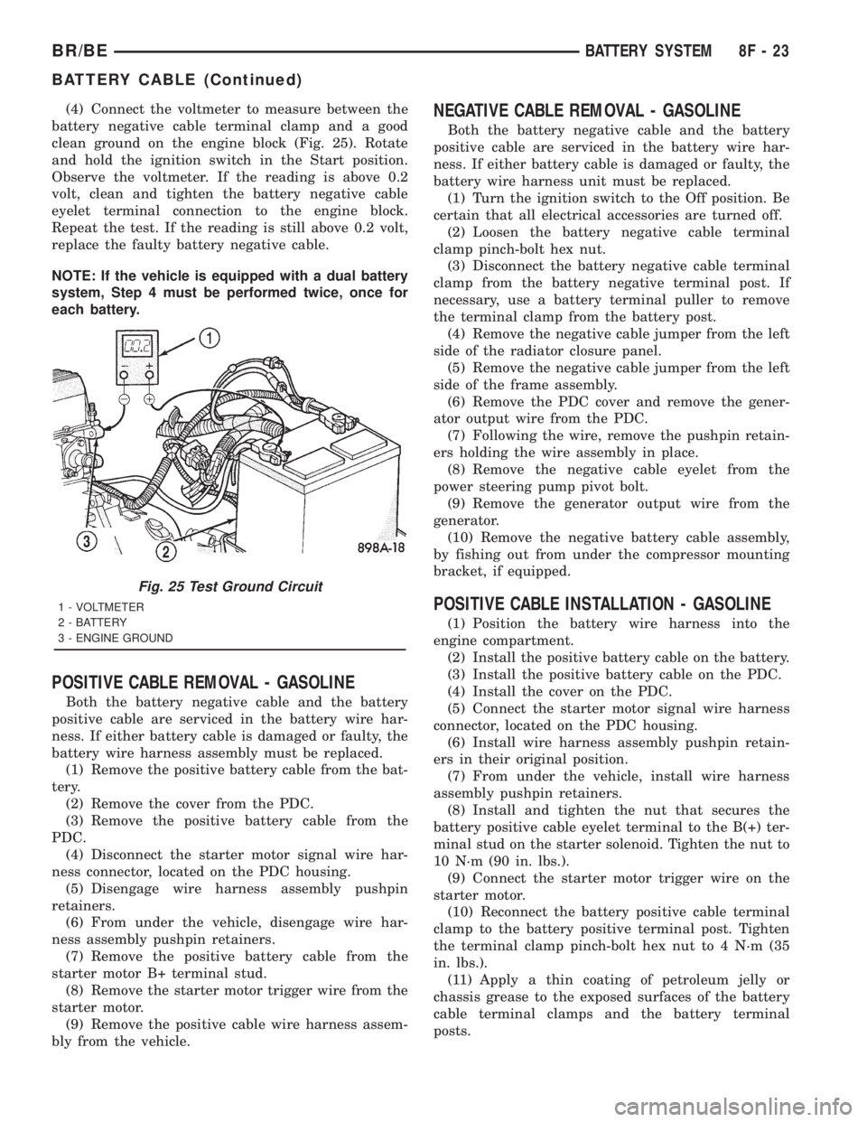
(4) Connect the voltmeter to measure between the
battery negative cable terminal clamp and a good
clean ground on the engine block (Fig. 25). Rotate
and hold the ignition switch in the Start position.
Observe the voltmeter. If the reading is above 0.2
volt, clean and tighten the battery negative cable
eyelet terminal connection to the engine block.
Repeat the test. If the reading is still above 0.2 volt,
replace the faulty battery negative cable.
NOTE: If the vehicle is equipped with a dual battery
system, Step 4 must be performed twice, once for
each battery.
POSITIVE CABLE REMOVAL - GASOLINE
Both the battery negative cable and the battery
positive cable are serviced in the battery wire har-
ness. If either battery cable is damaged or faulty, the
battery wire harness assembly must be replaced.
(1) Remove the positive battery cable from the bat-
tery.
(2) Remove the cover from the PDC.
(3) Remove the positive battery cable from the
PDC.
(4) Disconnect the starter motor signal wire har-
ness connector, located on the PDC housing.
(5) Disengage wire harness assembly pushpin
retainers.
(6) From under the vehicle, disengage wire har-
ness assembly pushpin retainers.
(7) Remove the positive battery cable from the
starter motor B+ terminal stud.
(8) Remove the starter motor trigger wire from the
starter motor.
(9) Remove the positive cable wire harness assem-
bly from the vehicle.
NEGATIVE CABLE REMOVAL - GASOLINE
Both the battery negative cable and the battery
positive cable are serviced in the battery wire har-
ness. If either battery cable is damaged or faulty, the
battery wire harness unit must be replaced.
(1) Turn the ignition switch to the Off position. Be
certain that all electrical accessories are turned off.
(2) Loosen the battery negative cable terminal
clamp pinch-bolt hex nut.
(3) Disconnect the battery negative cable terminal
clamp from the battery negative terminal post. If
necessary, use a battery terminal puller to remove
the terminal clamp from the battery post.
(4) Remove the negative cable jumper from the left
side of the radiator closure panel.
(5) Remove the negative cable jumper from the left
side of the frame assembly.
(6) Remove the PDC cover and remove the gener-
ator output wire from the PDC.
(7) Following the wire, remove the pushpin retain-
ers holding the wire assembly in place.
(8) Remove the negative cable eyelet from the
power steering pump pivot bolt.
(9) Remove the generator output wire from the
generator.
(10) Remove the negative battery cable assembly,
by fishing out from under the compressor mounting
bracket, if equipped.
POSITIVE CABLE INSTALLATION - GASOLINE
(1) Position the battery wire harness into the
engine compartment.
(2) Install the positive battery cable on the battery.
(3) Install the positive battery cable on the PDC.
(4) Install the cover on the PDC.
(5) Connect the starter motor signal wire harness
connector, located on the PDC housing.
(6) Install wire harness assembly pushpin retain-
ers in their original position.
(7) From under the vehicle, install wire harness
assembly pushpin retainers.
(8) Install and tighten the nut that secures the
battery positive cable eyelet terminal to the B(+) ter-
minal stud on the starter solenoid. Tighten the nut to
10 N´m (90 in. lbs.).
(9) Connect the starter motor trigger wire on the
starter motor.
(10) Reconnect the battery positive cable terminal
clamp to the battery positive terminal post. Tighten
the terminal clamp pinch-bolt hex nut to 4 N´m (35
in. lbs.).
(11) Apply a thin coating of petroleum jelly or
chassis grease to the exposed surfaces of the battery
cable terminal clamps and the battery terminal
posts.
Fig. 25 Test Ground Circuit
1 - VOLTMETER
2 - BATTERY
3 - ENGINE GROUND
BR/BEBATTERY SYSTEM 8F - 23
BATTERY CABLE (Continued)
Page 557 of 2889
With the engine running, remove spark plug cable
from spark plug (one at a time) and hold next to a
good engine ground. If the cable and spark plug are
in good condition, the engine rpm should drop and
the engine will run poorly. If engine rpm does not
drop, the cable and/or spark plug may not be operat-
ing properly and should be replaced. Also check
engine cylinder compression.
With the engine not running, connect one end of a
test probe to a good ground. Start the engine and run
the other end of the test probe along the entire
length of all spark plug cables. If cables are cracked
or punctured, there will be a noticeable spark jump
from the damaged area to the test probe. The cable
running from the ignition coil to the distributor cap
can be checked in the same manner. Cracked, dam-
aged or faulty cables should be replaced with resis-
tance type cable. This can be identified by the words
ELECTRONIC SUPPRESSION printed on the cable
jacket.
Use an ohmmeter to test for open circuits, exces-
sive resistance or loose terminals. If equipped,
remove the distributor cap from the distributor.Do
not remove cables from cap.Remove cable from
spark plug. Connect ohmmeter to spark plug termi-
nal end of cable and to corresponding electrode in
distributor cap. Resistance should be 250 to 1000
Ohms per inch of cable. If not, remove cable from dis-
tributor cap tower and connect ohmmeter to the ter-
minal ends of cable. If resistance is not within
specifications as found in the SPARK PLUG CABLE
RESISTANCE chart, replace the cable. Test all spark
plug cables in this manner.
SPARK PLUG CABLE RESISTANCE
MINIMUM MAXIMUM
250 Ohms Per Inch 1000 Ohms Per Inch
3000 Ohms Per Foot 12,000 Ohms Per Foot
To test ignition coil-to-distributor cap cable, do not
remove the cable from the cap. Connect ohmmeter to
rotor button (center contact) of distributor cap and
terminal at ignition coil end of cable. If resistance is
not within specifications as found in the Spark Plug
Cable Resistance chart, remove the cable from the
distributor cap. Connect the ohmmeter to the termi-
nal ends of the cable. If resistance is not within spec-
ifications as found in the Spark Plug Cable
Resistance chart, replace the cable. Inspect the igni-
tion coil tower for cracks, burns or corrosion.
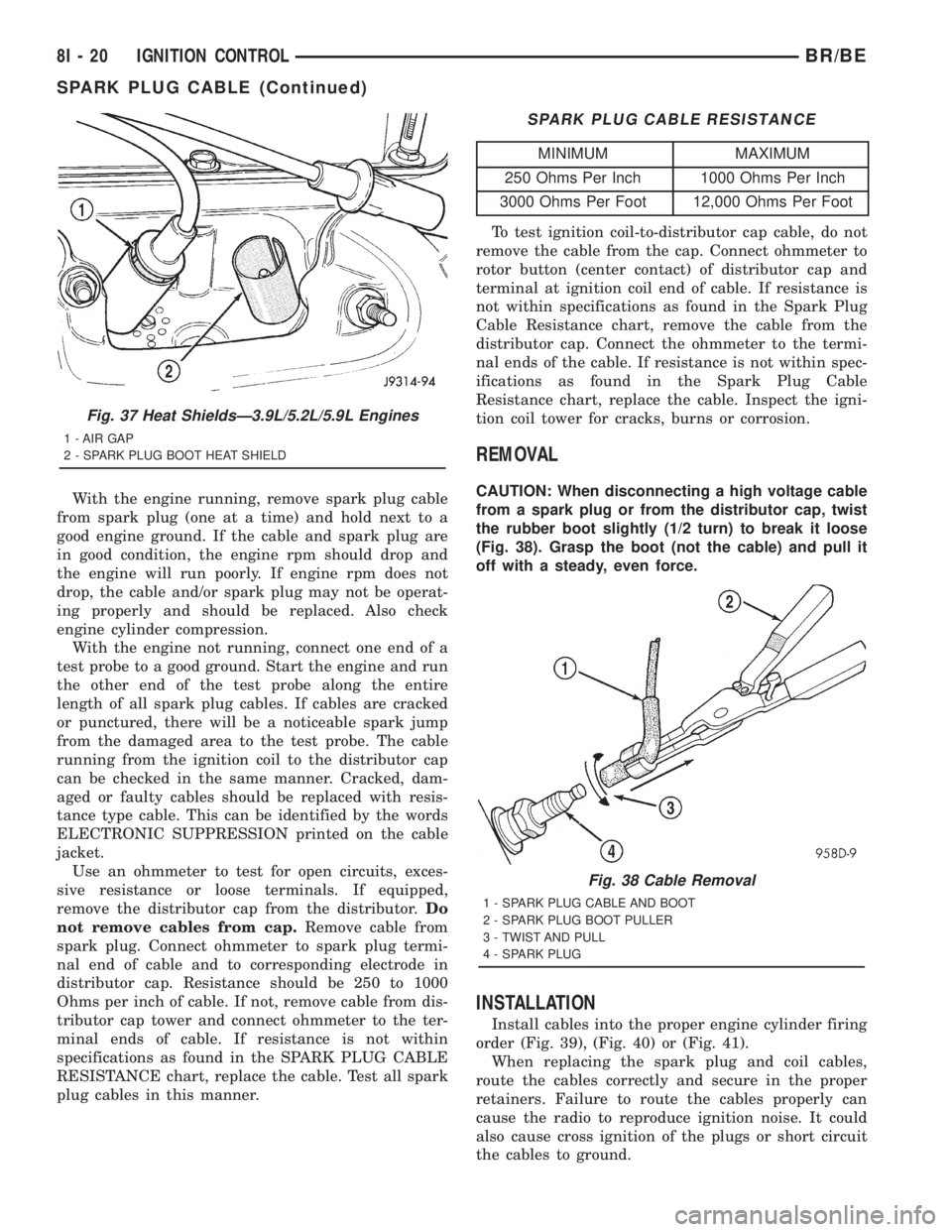
REMOVAL
CAUTION: When disconnecting a high voltage cable
from a spark plug or from the distributor cap, twist
the rubber boot slightly (1/2 turn) to break it loose
(Fig. 38). Grasp the boot (not the cable) and pull it
off with a steady, even force.
INSTALLATION
Install cables into the proper engine cylinder firing
order (Fig. 39), (Fig. 40) or (Fig. 41).
When replacing the spark plug and coil cables,
route the cables correctly and secure in the proper
retainers. Failure to route the cables properly can
cause the radio to reproduce ignition noise. It could
also cause cross ignition of the plugs or short circuit
the cables to ground.
Fig. 37 Heat ShieldsÐ3.9L/5.2L/5.9L Engines
1 - AIR GAP
2 - SPARK PLUG BOOT HEAT SHIELD
Fig. 38 Cable Removal
1 - SPARK PLUG CABLE AND BOOT
2 - SPARK PLUG BOOT PULLER
3 - TWIST AND PULL
4 - SPARK PLUG
8I - 20 IGNITION CONTROLBR/BE
SPARK PLUG CABLE (Continued)
Page 588 of 2889
SHIFT INDICATOR (TRANSFER
CASE)
DESCRIPTION
A four-wheel drive indicator is standard equipment
on all instrument clusters. However, on vehicles not
equipped with the optional four-wheel drive system,
this indicator is mechanically disabled. The four-
wheel drive indicator is located near the lower edge
of the instrument cluster overlay, to the right of cen-
ter. The four-wheel drive indicator consists of a sten-
cilled cutout of the text ª4WDº in the opaque layer of
the instrument cluster overlay. The dark outer layer
of the overlay prevents the indicator from being
clearly visible when it is not illuminated. An amber
lens behind the cutout in the opaque layer of the
overlay causes the ª4WDº text to appear in amber
through the translucent outer layer of the overlay
when the indicator is illuminated from behind by a
Light Emitting Diode (LED) soldered onto the instru-
ment cluster electronic circuit board. The four-wheel
drive indicator is serviced as a unit with the instru-
ment cluster.
OPERATION
The four-wheel drive indicator lamp gives an indi-
cation to the vehicle operator that a four-wheel drive
operating mode is engaged. The indicator will be illu-
minated when either high range (4H) or low range
(4L) have been selected with the transfer case shift
lever. This indicator is controlled by a transistor on
the instrument cluster circuit board based upon the
cluster programming, and a hard wired input from
the four-wheel drive switch on the front axle discon-
nect housing. The four-wheel drive indicator Light
Emitting Diode (LED) receives battery current on the
instrument cluster electronic circuit board through
the fused ignition switch output (st-run) circuit
whenever the ignition switch is in the On or Start
positions; therefore, the lamp will always be off when
the ignition switch is in any position except On or
Start. The LED only illuminates when it is switched
to ground by the instrument cluster transistor.
The four-wheel drive switch is connected in series
between ground and the four-wheel drive switch
sense input to the instrument cluster. For further
information on the transfer case and the transfer
case operating ranges, (Refer to 21 - TRANSMIS-
SION/TRANSAXLE/TRANSFER CASE - OPERA-
TION. For further information on the front axle
disconnect mechanism, (Refer to 3 - DIFFERENTIAL
& DRIVELINE/FRONT AXLE/AXLE VACUUM
MOTOR - OPERATION). The four-wheel drive switch
input to the instrument cluster circuitry can be diag-nosed using conventional diagnostic tools and meth-
ods.
DIAGNOSIS AND TESTING - FOUR-WHEEL
DRIVE INDICATOR
The diagnosis found here addresses an inoperative
four-wheel drive indicator condition. If the problem
being diagnosed is related to indicator accuracy, be
certain to confirm that the problem is with the indi-
cator and not with a damaged or inoperative front
axle disconnect mechanism. (Refer to 3 - DIFFEREN-
TIAL & DRIVELINE/FRONT AXLE/AXLE VACUUM
MOTOR - DIAGNOSIS AND TESTING). If no front
axle disconnect problem is found, the following proce-
dure will help locate a short or open in the four-
wheel drive switch input to the instrument cluster.
Refer to the appropriate wiring information. The wir-
ing information includes wiring diagrams, proper
wire and connector repair procedures, details of wire
harness routing and retention, connector pin-out
information and location views for the various wire
harness connectors, splices and grounds.
WARNING: ON VEHICLES EQUIPPED WITH AIR-
BAGS, DISABLE THE AIRBAG SYSTEM BEFORE
ATTEMPTING ANY STEERING WHEEL, STEERING
COLUMN, OR INSTRUMENT PANEL COMPONENT
DIAGNOSIS OR SERVICE. DISCONNECT AND ISO-
LATE THE BATTERY NEGATIVE (GROUND) CABLE,
THEN WAIT TWO MINUTES FOR THE AIRBAG SYS-
TEM CAPACITOR TO DISCHARGE BEFORE PER-
FORMING FURTHER DIAGNOSIS OR SERVICE. THIS
IS THE ONLY SURE WAY TO DISABLE THE AIRBAG
SYSTEM. FAILURE TO TAKE THE PROPER PRE-
CAUTIONS COULD RESULT IN ACCIDENTAL AIR-
BAG DEPLOYMENT AND POSSIBLE PERSONAL
INJURY.
INDICATOR DOES NOT ILLUMINATE WITH FOUR-WHEEL
DRIVE MODE SELECTED
(1) Disconnect and isolate the battery negative
cable. Disconnect the engine wire harness connector
for the four-wheel drive switch from the switch con-
nector receptacle. Check for continuity between the
ground circuit cavity of the engine wire harness con-
nector for the four-wheel drive switch and a good
ground. There should be continuity. If OK, go to Step
2. If not OK, repair the open ground circuit to ground
(G100) as required.
(2) Reconnect the battery negative cable. Turn the
ignition switch to the On position. Install a jumper
wire between the 4WD switch sense circuit cavity of
the engine wire harness connector for the four-wheel
drive switch and a good ground. The four-wheel drive
indicator should light. If OK, replace the faulty four-
wheel drive switch. If not OK, go to Step 3.
BR/BEINSTRUMENT CLUSTER 8J - 29
Page 647 of 2889

DIAGNOSIS & TESTING - AMBIENT
TEMPERATURE SENSOR
The thermometer function is supported by the
ambient temperature sensor, a wiring circuit, and a
portion of the compass mini-trip computer module. If
any portion of the ambient temperature sensor cir-
cuit fails, the compass/thermometer display function
will self-diagnose the circuit. If 55É C (131É F)
appears in the display, the sensor is being exposed to
temperatures above 55É C (131É F), or the sensor cir-
cuit is shorted. If ±40É C (±40É F) appears in the dis-
play, the sensor is being exposed to temperatures
below ±40É C (±40É F), or the sensor circuit is open.
The ambient temperature sensor circuit can also be
diagnosed using the following Sensor Test, and Sen-
sor Circuit Test. If the temperature sensor and cir-
cuit are confirmed to be OK, but the temperature
display is inoperative or incorrect, refer toCompass
Mini-Trip Computerin the Diagnosis and Testing
section of this group. For complete circuit diagrams,
refer toOverhead Consolein the Contents of Wir-
ing Diagrams.
SENSOR TEST
(1) Turn the ignition switch to the Off position.
Disconnect and isolate the battery negative cable.
Disconnect the ambient temperature sensor wire har-
ness connector.
(2) Measure the resistance of the ambient temper-
ature sensor. At ±40É C (±40É F), the sensor resis-
tance is 336 kilohms. At 55É C (131É F), the sensor
resistance is 2.488 kilohms. The sensor resistance
should read between these two values. If OK, refer to
Sensor Circuit Testin the Diagnosis and Testing
section of this group. If not OK, replace the faulty
ambient temperature sensor.
SENSOR CIRCUIT TEST
(1) Turn the ignition switch to the Off position.
Disconnect and isolate the battery negative cable.
Disconnect the ambient temperature sensor wire har-
ness connector and the overhead console wire har-
ness connector.
(2) Connect a jumper wire between the two termi-
nals in the body half of the ambient temperature sen-
sor wire harness connector.
(3) Check for continuity between the sensor return
circuit and the ambient temperature sensor signal
circuit cavities of the roof wire harness overhead con-
sole connector. There should be continuity. If OK, go
to Step 4. If not OK, repair the open sensor return
circuit or ambient temperature sensor signal circuit
to the ambient temperature sensor as required.(4) Remove the jumper wire from the body half of
the ambient temperature sensor wire harness con-
nector. Check for continuity between the sensor
return circuit cavity of the roof wire harness over-
head console connector and a good ground. There
should be no continuity. If OK, go to Step 5. If not
OK, repair the shorted sensor return circuit as
required.
(5) Check for continuity between the ambient tem-
perature sensor signal circuit cavity of the roof wire
harness overhead console connector and a good
ground. There should be no continuity. If OK, refer to
Compass Mini-Trip Computerin the Diagnosis
and Testing section of this group. If not OK, repair
the shorted ambient temperature sensor signal cir-
cuit as required.
REMOVAL
(1) Disconnect and isolate the battery negative
cable.
(2) Locate the ambient temperature sensor, on the
underside of the hood near the hood latch striker
(Fig. 8).
(3) Disconnect the wire harness connector from the
ambient temperature sensor connector receptacle.
(4) Remove the one screw that secures the ambient
temperature sensor bracket to the inner hood rein-
forcement.
(5) Remove the ambient temperature sensor from
the inner hood reinforcement.
Fig. 8 Ambient Temperature Sensor Remove/Install
1 - HOOD
2 - SCREW
3 - SENSOR AND BRACKET
4 - WIRE HARNESS CONNECTOR
5 - HOOD LATCH STRIKER
8M - 12 MESSAGE SYSTEMSBR/BE
AMBIENT TEMP SENSOR (Continued)
Page 663 of 2889
(4) Disconnect and isolate the battery negative
cable. Check for continuity between the ground cir-
cuit cavity in the door wire harness half of the power
mirror switch wire harness connector and a good
ground. There should be continuity. If OK, go to Step
5. If not OK, repair the circuit to ground as required.
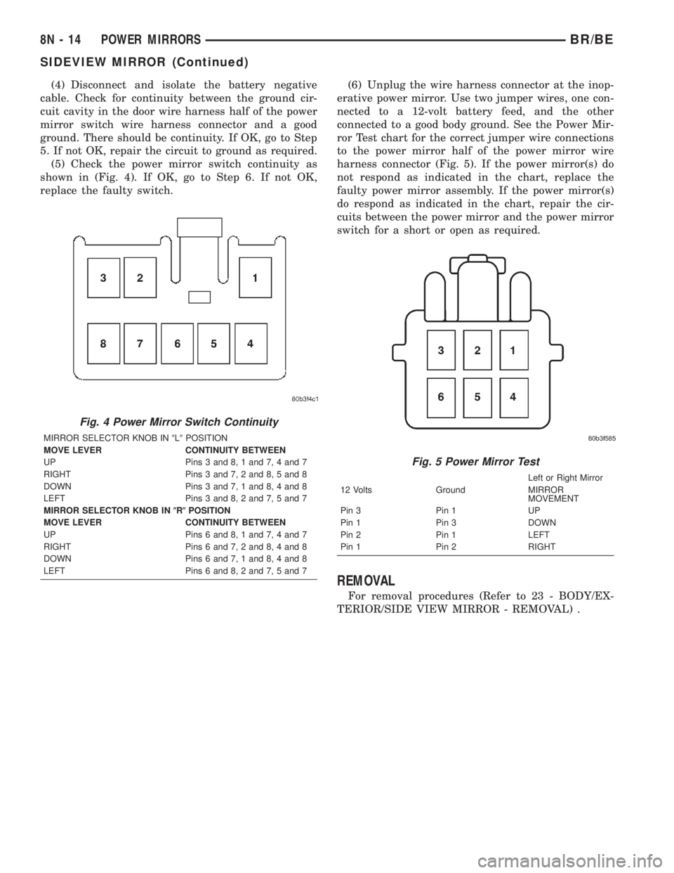
(5) Check the power mirror switch continuity as
shown in (Fig. 4). If OK, go to Step 6. If not OK,
replace the faulty switch.(6) Unplug the wire harness connector at the inop-
erative power mirror. Use two jumper wires, one con-
nected to a 12-volt battery feed, and the other
connected to a good body ground. See the Power Mir-
ror Test chart for the correct jumper wire connections
to the power mirror half of the power mirror wire
harness connector (Fig. 5). If the power mirror(s) do
not respond as indicated in the chart, replace the
faulty power mirror assembly. If the power mirror(s)
do respond as indicated in the chart, repair the cir-
cuits between the power mirror and the power mirror
switch for a short or open as required.
REMOVAL
For removal procedures (Refer to 23 - BODY/EX-
TERIOR/SIDE VIEW MIRROR - REMOVAL) .
Fig. 4 Power Mirror Switch Continuity
MIRROR SELECTOR KNOB IN9L9POSITION
MOVE LEVER CONTINUITY BETWEEN
UP Pins 3 and 8, 1 and 7, 4 and 7
RIGHT Pins 3 and 7, 2 and 8, 5 and 8
DOWN Pins 3 and 7, 1 and 8, 4 and 8
LEFT Pins 3 and 8, 2 and 7, 5 and 7
MIRROR SELECTOR KNOB IN(R(POSITION
MOVE LEVER CONTINUITY BETWEEN
UP Pins 6 and 8, 1 and 7, 4 and 7
RIGHT Pins 6 and 7, 2 and 8, 4 and 8
DOWN Pins 6 and 7, 1 and 8, 4 and 8
LEFT Pins 6 and 8, 2 and 7, 5 and 7
Fig. 5 Power Mirror Test
Left or Right Mirror
12 Volts Ground MIRROR
MOVEMENT
Pin 3 Pin 1 UP
Pin 1 Pin 3 DOWN
Pin 2 Pin 1 LEFT
Pin 1 Pin 2 RIGHT
8N - 14 POWER MIRRORSBR/BE
SIDEVIEW MIRROR (Continued)