2001 DODGE RAM buttons
[x] Cancel search: buttonsPage 434 of 2889
²Radio memory presets not working properly
²Volume changes with no remote radio switch
input
²Remote radio switch buttons taking on other
functions
²CD player skipping tracks
²Remote radio switch inoperative.
For complete circuit diagrams, refer to the appro-
priate wiring information. The wiring information
includes wiring diagrams, proper wire and connector
repair procedures, details of wire harness routing
and retention, connector pin-out information and
location views for the various wire harness connec-
tors, splices and grounds.
WARNING: ON VEHICLES EQUIPPED WITH AIR-
BAGS, REFER TO ELECTRICAL, RESTRAINTS
BEFORE ATTEMPTING ANY STEERING WHEEL,
STEERING COLUMN, OR INSTRUMENT PANEL
COMPONENT DIAGNOSIS OR SERVICE. FAILURE
TO TAKE THE PROPER PRECAUTIONS COULD
RESULT IN ACCIDENTAL AIRBAG DEPLOYMENT
AND POSSIBLE PERSONAL INJURY.
CAUTION: The speaker output of the radio receiver
is a ªfloating groundº system. Do not allow any
speaker lead to short to ground, as damage to the
radio receiver may result.
(1) Check the fused B(+) fuse in the junction block.
If OK, go to Step 2. If not OK, repair the shorted cir-
cuit or component as required and replace the faulty
fuse.
(2) Check for battery voltage at the fused B(+) fuse
in the junction block. If OK, go to Step 3. If not OK,
repair the open fused B(+) circuit to the Power Dis-
tribution Center (PDC) as required.
(3) Check the fused ignition switch output (acc/
run) fuse in the junction block. If OK, go to Step 4. If
not OK, repair the shorted circuit or component as
required and replace the faulty fuse(s).
(4) Turn the ignition switch to the On position.
Check for battery voltage at the fused ignition switch
output (acc/run) fuse in the junction block. If OK, go
to Step 5. If not OK, repair the open fused ignition
switch output (acc/run) circuit to the ignition switch
as required.
(5) Turn the ignition switch to the Off position.
Disconnect and isolate the battery negative cable.
Remove the radio receiver from the instrument
panel, but do not disconnect the wire harness connec-
tors. Check for continuity between the radio receiver
chassis and a good ground. There should be continu-
ity. If OK, go to Step 6. If not OK, repair the open
ground circuit to ground as required.(6) Connect the battery negative cable. Turn the
ignition switch to the On position. Check for battery
voltage at the fused ignition switch output (acc/run)
circuit cavity of the left (gray) radio wire harness
connector. If OK, go to Step 7. If not OK, repair the
open fused ignition switch output (acc/run) circuit to
the junction block fuse as required.
(7) Turn the ignition switch to the Off position.
Check for battery voltage at the fused B(+) circuit
cavity of the left (gray) radio wire harness connector.
If OK, replace the faulty radio receiver. If not OK,
repair the open fused B(+) circuit to the junction
block fuse as required.
REMOVAL
(1) Disconnect and isolate the battery negative
cable.
(2) Remove the cluster bezel from the instrument
panel.
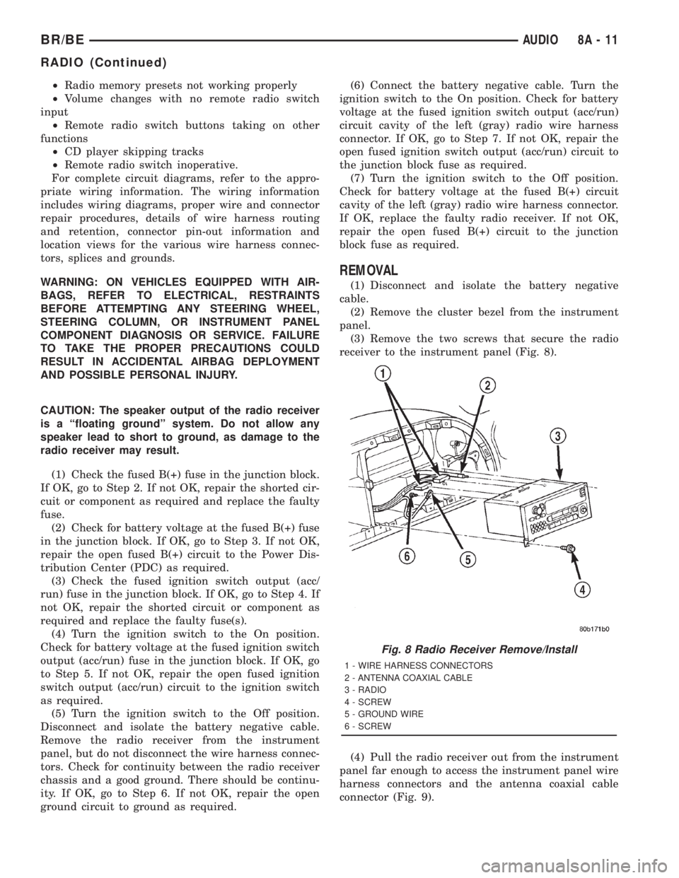
(3) Remove the two screws that secure the radio
receiver to the instrument panel (Fig. 8).
(4) Pull the radio receiver out from the instrument
panel far enough to access the instrument panel wire
harness connectors and the antenna coaxial cable
connector (Fig. 9).
Fig. 8 Radio Receiver Remove/Install
1 - WIRE HARNESS CONNECTORS
2 - ANTENNA COAXIAL CABLE
3 - RADIO
4 - SCREW
5 - GROUND WIRE
6 - SCREW
BR/BEAUDIO 8A - 11
RADIO (Continued)
Page 636 of 2889
MESSAGE SYSTEMS
TABLE OF CONTENTS
page page
OVERHEAD CONSOLE
DESCRIPTION............................1
STANDARD PROCEDURE...................4
COMPASS CALIBRATION..................4
COMPASS VARIATION ADJUSTMENT........4
COMPASS DEMAGNETIZING...............5
REMOVAL...............................6
DISASSEMBLY............................7
ASSEMBLY..............................7
INSTALLATION............................8
SPECIAL TOOLS..........................8
COMPASS/MINI-TRIP COMPUTER
DESCRIPTION............................8OPERATION.............................9
DIAGNOSIS AND TESTING.................10
COMPASS MINI-TRIP COMPUTER..........10
REMOVAL..............................11
INSTALLATION...........................11
AMBIENT TEMP SENSOR
DESCRIPTION...........................11
OPERATION.............................11
DIAGNOSIS AND TESTING.................12
AMBIENT TEMPERATURE SENSOR........12
REMOVAL..............................12
INSTALLATION...........................13
OVERHEAD CONSOLE
DESCRIPTION
Two different overhead console units are available
factory-installed options on this model, base or pre-
mium. The base overhead console unit features a
garage door opener storage bin, a sunglasses storage
bin and two reading and courtesy lamps. The pre-
mium overhead console has all of the features of the
base unit, but adds a compass mini-trip computer.
See the owner's manual in the vehicle glove box for
more information on the features, use and operation
of all of the overhead console components and sys-
tems. Refer toOverhead Consolein the Contents of
Wiring Diagrams for complete circuit diagrams.
The premium overhead console (Fig. 1) includes
two front-mounted reading and courtesy lamps, a
garage door opener storage bin, and a sunglasses
storage bin. The premium overhead console includes
a compass mini-trip computer. The base overhead
console uses the same overhead console housing, but
has a computer cover plug installed in place of the
compass mini-trip computer display module lens and
push buttons.
The rear of the overhead console is secured to two
rear mounting holes in the inner roof panel by two
plastic hook formations that are integral to the over-
head console housing. The front of the overhead con-
sole is secured to the two front mounting holes of the
inner roof panel by two plastic latches that are inte-
gral to the overhead console housing. A single electri-
cal connection joins the overhead console wireharness to the roof wire harness for both the base
and premium overhead console units.
Following are general descriptions of the major
components used in the overhead console. See the
owner's manual in the vehicle glove box for more
information on the use and operation of the various
overhead console features.
GARAGE DOOR OPENER STORAGE BIN
A compartment near the front of the overhead con-
sole is designed to hold most garage door opener
remote control transmitters. The transmitter is
mounted within the compartment with an adhesive-
backed hook and loop fastener patch and, when the
compartment is closed, a push button in the center of
the compartment door is depressed to actuate the
transmitter.
A transmitter mounting kit including the adhesive-
backed hook and loop fastener material is available
for service. The garage door opener storage bin door
and the push button with three assorted length
adapter pegs are also available for service replace-
ment.
The garage door opener storage compartment door
is opened by pressing the integral latch towards the
front of the vehicle. When the compartment door is
opened, the push button unit is removed from the
compartment by squeezing the latch tabs and pulling
the unit downward. With the push button removed,
the garage door opener can be installed in the com-
partment using the adhesive-backed hook and loop
fastener material provided.
BR/BEMESSAGE SYSTEMS 8M - 1
Page 639 of 2889
while maintaining a speed of 48 kilometers-per-hour
(30 miles-per-hour) or higher.
The thermometer function is supported by an
ambient temperature sensor. The sensor is mounted
outside the passenger compartment near the front
and center of the vehicle, and is hard wired to the
module. The ambient temperature sensor is available
as a separate service item.
STANDARD PROCEDURE - COMPASS
CALIBRATION
CAUTION: Do not place any external magnets, such
as magnetic roof mount antennas, in the vicinity of
the compass. Do not use magnetic tools when ser-
vicing the overhead console.
The electronic compass unit features a self-cali-
brating design, which simplifies the calibration pro-
cedure. This feature automatically updates the
compass calibration while the vehicle is being driven.
This allows the compass unit to compensate for small
changes in the residual magnetism that the vehicle
may acquire during normal use. If the compass read-
ings appear to be erratic or out of calibration, per-
form the following calibration procedure. Also, new
service replacement compass mini-trip computer
modules must have their compass calibrated using
this procedure. Do not attempt to calibrate the com-
pass near large metal objects such as other vehicles,
large buildings, or bridges; or, near overhead or
underground power lines.
(1) Start the engine. If the compass/temperature
data is not currently being displayed, momentarily
depress and release the Step push button to step
through the display options until you have reached
the compass/temperature display.
(2) Depress both the U.S./Metric and the Step
push buttons at the same time for more than six sec-
onds, until ªCALº appears in the display, then release
both push buttons. The ªCALº in the display indi-
cates that the compass is in the calibration mode.
(3) Drive the vehicle on a level surface, at least
fifty feet away from large metal objects and power
lines, in all four compass directions, such as driving
around a city block several times or driving in two to
three complete circles at a slow to medium speed.
(4) When the calibration is successfully completed,
ªCALº will disappear from the display and normal
compass mini-trip computer operation will resume.
NOTE: If the ªCALº message remains in the display,
either there is excessive magnetism near the com-
pass, or the unit is faulty. Repeat the calibration
procedure at least one more time.NOTE: If the wrong direction is still indicated in the
compass display, the area selected for calibration
may be too close to a strong magnetic field. Repeat
the calibration procedure in another location.
STANDARD PROCEDURE - COMPASS
VARIATION ADJUSTMENT
Compass variance, also known as magnetic decli-
nation, is the difference in angle between magnetic
north and true geographic north. In some geographic
locations, the difference between magnetic and geo-
graphic north is great enough to cause the compass
to give false readings. If this problem occurs, the
compass variance must be set. There are two meth-
ods that can be used to enter this information into
the compass mini-trip computer module. They are
the zone method and the direct method.
ZONE METHOD
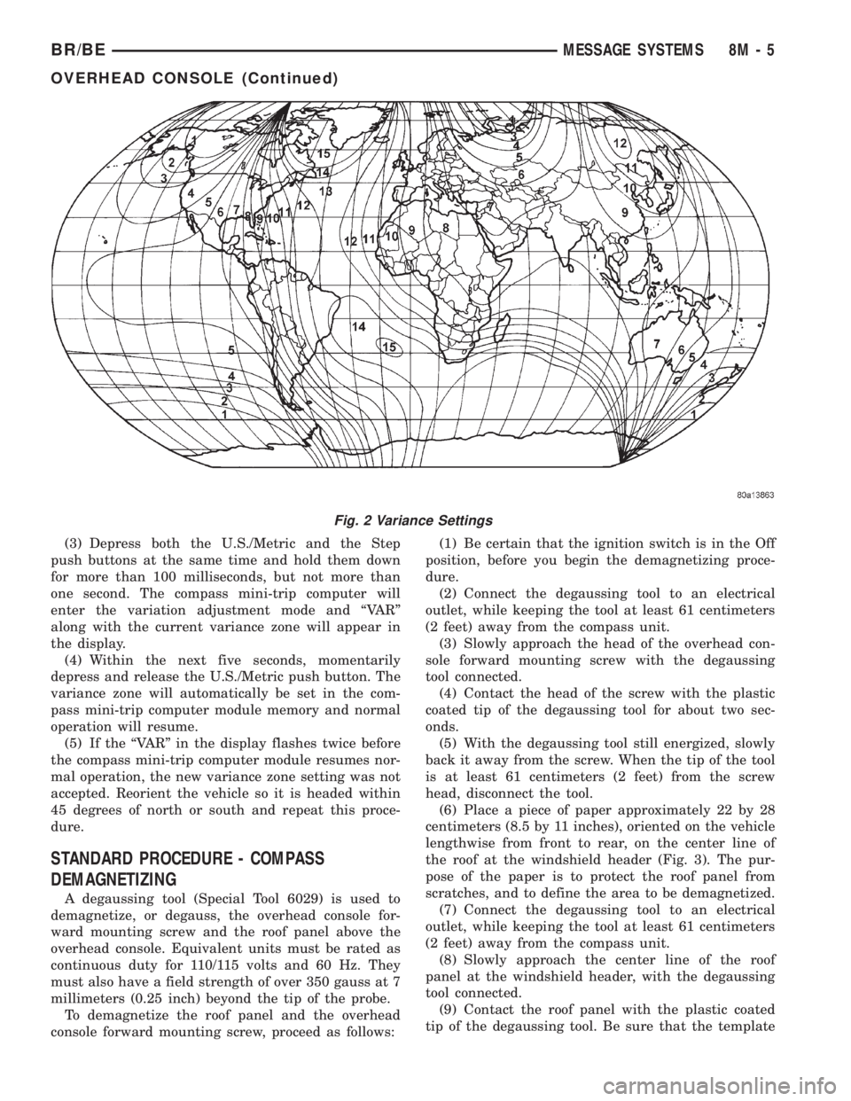
(1) Using the Variance Settings map, find your
geographic location and note the zone number (Fig.
2).
(2) Turn the ignition switch to the On position. If
the compass/temperature data is not currently being
displayed, momentarily depress and release the Step
push button to step through the display options until
you have reached the compass/temperature display.
(3) Depress both the U.S./Metric and the Step
push buttons at the same time and hold them down
for more than 100 milliseconds, but not more than
one second. The compass mini-trip computer will
enter the variation adjustment mode and ªVARº
along with the current variance zone will appear in
the display.
(4) Momentarily depress and release the Step push
button to step through the zone numbers, until the
zone number for your geographic location appears in
the display.
(5) After five seconds, the displayed zone will auto-
matically be set in the compass mini-trip computer
module memory and normal operation will resume.
(6) Confirm that the correct directions are now
indicated by the compass.
DIRECT METHOD
(1) Turn the vehicle so it is headed in either the
north or south direction. The vehicle must be headed
within 45 degrees of north or south for this procedure
to work. The vehicle may be moving or stationary.
(2) Turn the ignition switch to the On position. If
the compass/temperature data is not currently being
displayed, momentarily depress and release the Step
push button to step through the display options until
you have reached the compass/temperature display.
8M - 4 MESSAGE SYSTEMSBR/BE
OVERHEAD CONSOLE (Continued)
Page 640 of 2889
(3) Depress both the U.S./Metric and the Step
push buttons at the same time and hold them down
for more than 100 milliseconds, but not more than
one second. The compass mini-trip computer will
enter the variation adjustment mode and ªVARº
along with the current variance zone will appear in
the display.
(4) Within the next five seconds, momentarily
depress and release the U.S./Metric push button. The
variance zone will automatically be set in the com-
pass mini-trip computer module memory and normal
operation will resume.
(5) If the ªVARº in the display flashes twice before
the compass mini-trip computer module resumes nor-
mal operation, the new variance zone setting was not
accepted. Reorient the vehicle so it is headed within
45 degrees of north or south and repeat this proce-
dure.
STANDARD PROCEDURE - COMPASS
DEMAGNETIZING
A degaussing tool (Special Tool 6029) is used to
demagnetize, or degauss, the overhead console for-
ward mounting screw and the roof panel above the
overhead console. Equivalent units must be rated as
continuous duty for 110/115 volts and 60 Hz. They
must also have a field strength of over 350 gauss at 7
millimeters (0.25 inch) beyond the tip of the probe.
To demagnetize the roof panel and the overhead
console forward mounting screw, proceed as follows:(1) Be certain that the ignition switch is in the Off
position, before you begin the demagnetizing proce-
dure.
(2) Connect the degaussing tool to an electrical
outlet, while keeping the tool at least 61 centimeters
(2 feet) away from the compass unit.
(3) Slowly approach the head of the overhead con-
sole forward mounting screw with the degaussing
tool connected.
(4) Contact the head of the screw with the plastic
coated tip of the degaussing tool for about two sec-
onds.
(5) With the degaussing tool still energized, slowly
back it away from the screw. When the tip of the tool
is at least 61 centimeters (2 feet) from the screw
head, disconnect the tool.
(6) Place a piece of paper approximately 22 by 28
centimeters (8.5 by 11 inches), oriented on the vehicle
lengthwise from front to rear, on the center line of
the roof at the windshield header (Fig. 3). The pur-
pose of the paper is to protect the roof panel from
scratches, and to define the area to be demagnetized.
(7) Connect the degaussing tool to an electrical
outlet, while keeping the tool at least 61 centimeters
(2 feet) away from the compass unit.
(8) Slowly approach the center line of the roof
panel at the windshield header, with the degaussing
tool connected.
(9) Contact the roof panel with the plastic coated
tip of the degaussing tool. Be sure that the template
Fig. 2 Variance Settings
BR/BEMESSAGE SYSTEMS 8M - 5
OVERHEAD CONSOLE (Continued)
Page 644 of 2889
Compass mini-trip computer units for vehicles
equipped with the VTSS include a red Light-Emit-
ting Diode (LED) on their electronic circuit board.
This LED protrudes through the bottom of the lens
on the front of the overhead console unit, and serves
as the security indicator lamp. Refer toSecurity
Indicator Lampin Vehicle Theft/Security Systems
for more information on this feature.
The compass mini-trip computer module contains a
central processing unit and interfaces with other
electronic modules in the vehicle on the Chrysler Col-
lision Detection (CCD) data bus network. The CCD
data bus network allows the sharing of sensor infor-
mation. This helps to reduce wire harness complexity,
reduce internal controller hardware, and reduce com-
ponent sensor current loads. At the same time, this
system provides increased reliability, enhanced diag-
nostics, and allows the addition of many new feature
capabilities.
The compass mini-trip computer provides several
electronic functions and features. Some of the func-
tions and features that the compass mini-trip com-
puter module supports and/or controls, include the
following display options:
²Compass and temperature- provides the out-
side temperature and one of eight compass readings
to indicate the direction the vehicle is facing.
²Compass and compass in degrees- provides
one of eight compass readings to indicate the direc-
tion the vehicle is facing and provides the compass
direction in degrees.
²Trip odometer (ODO)- shows the distance
travelled since the last trip computer reset.
²Average fuel economy (AVG ECO)- shows
the average fuel economy since the last trip computer
reset.
²Instant fuel economy (ECO)- shows the
present fuel economy based upon the current vehicle
distance and fuel used information.
²Distance to empty (DTE)- shows the esti-
mated distance that can be travelled with the fuel
remaining in the fuel tank. This estimated distance
is computed using the average miles-per-gallon from
the last 30 gallons of fuel used.
²Elapsed time (ET)- shows the accumulated
ignition-on time since the last trip computer reset.
²Blank screen- the compass mini-trip VFD is
turned off.
The ambient temperature sensor is hard wired to
the compass mini-trip computer module. Data input
for all other compass mini-trip computer functions,
including VFD dimming level, is received through
CCD data bus messages. The compass mini-trip com-
puter uses its internal programming and all of these
inputs to calculate and display the requested data. If
the data displayed is incorrect, perform the self-diag-nostic tests as described in this group. If these tests
prove inconclusive, the use of a DRBIIItscan tool
and the proper Diagnostic Procedures manual are
recommended for further testing of the compass
mini-trip computer module and the CCD data bus.
The compass mini-trip computer module cannot be
repaired, and is available for service only as a unit. If
faulty or damaged, the complete module must be
replaced.
OPERATION
The compass mini-trip computer only operates with
the ignition switch in the On position. When the igni-
tion switch is turned to the On position, all of the
segments in the compass mini-trip computer VFD
will be turned on for one second, then the display
will return to the last function being displayed before
the ignition was turned to the Off position. With the
ignition switch in the On position, momentarily
depressing and releasing the Step push button switch
will cause the compass-mini-trip computer to change
its mode of operation, and momentarily depressing
and releasing the U.S./Metric push button will cause
the unit to toggle between U.S. and Metric measure-
ments. While in either compass mode, depressing the
U.S./Metric push button for more than ten seconds
will toggle the display between the compass/temper-
ature and the compass/compass in degrees modes.
This compass mini-trip computer features several
functions that can be reset. If both the Step and U.S./
Metric push buttons are depressed at the same time
with the ignition switch in the On position, the trip
computer information that can be reset is reset.
Depressing and releasing the Step and U.S./Metric
push buttons at the same time for more than 100
milliseconds, but not more than one second while in
any display mode (except the compass/temperature
mode) will cause a local reset. A local reset affects
only the function currently displayed. See the Reset
Chart below for more information on this feature.
Performing a local reset while in the compass/tem-
perature mode enters the module into the compass
variance setting mode.
Depressing and releasing the Step and U.S./Metric
push buttons at the same time for more than two
seconds while in any display mode (except the com-
pass/temperature mode) will cause a global reset. A
global reset changes all of the trip computer func-
tions that can be reset.
For more information on the features and control
functions of the compass mini-trip computer, see the
owner's manual in the vehicle glove box.
BR/BEMESSAGE SYSTEMS 8M - 9
COMPASS/MINI-TRIP COMPUTER (Continued)
Page 645 of 2889

DIAGNOSIS & TESTING - COMPASS MINI-TRIP
COMPUTER
If the problem with the compass mini-trip com-
puter module is an inoperative security indicator
lamp, refer toSecurity Indicator Lampin Vehicle
Theft/Security Systems. If the problem with the com-
pass mini-trip computer module is an ªOCº or ªSCº in
the compass/thermometer display, refer toAmbient
Temperature Sensorin the Diagnosis and Testing
section of this group. If the problem with the com-
pass mini-trip computer module is an inaccurate or
scrambled display, refer toSelf-Diagnostic Testin
the Diagnosis and Testing section of this group. If the
problem with the compass mini-trip computer module
is incorrect Vacuum Fluorescent Display (VFD) dim-
ming levels, use a DRBtscan tool and the proper
Diagnostic Procedures manual to test for the correct
dimming message inputs being received from the
instrument cluster over the Chrysler Collision Detec-
tion (CCD) data bus. If the problem is a no-display
condition, use the following procedures. For complete
circuit diagrams, refer toOverhead Consolein the
Contents of Wiring Diagrams.
(1) Check the fused B(+) fuse in the junction block.
If OK, go to Step 2. If not OK, repair the shorted cir-
cuit or component as required and replace the faulty
fuse.
(2) Check for battery voltage at the fused B(+) fuse
in the junction block. If OK, go to Step 3. If not OK,
repair the open fused B(+) circuit to the battery as
required.
(3) Check the fused ignition switch output (run/
start) fuse in the junction block. If OK, go to Step 4.
If not OK, repair the shorted circuit or component as
required and replace the faulty fuse.
(4) Turn the ignition switch to the On position.
Check for battery voltage at the fused ignition switch
output (run/start) fuse in the junction block. If OK,
go to Step 5. If not OK, repair the open fused ignition
switch output (run/start) circuit to the ignition switch
as required.
(5) Turn the ignition switch to the Off position.
Disconnect and isolate the battery negative cable.
Remove the overhead console. Check for continuity
between the ground circuit cavities of the roof wire
harness connector for the overhead console and a
good ground. There should be continuity. If OK, go to
Step 6. If not OK, repair the open ground circuit to
ground as required.
(6) Connect the battery negative cable. Check for
battery voltage at the fused B(+) circuit cavity of the
roof wire harness connector for the overhead console.
If OK, go to Step 7. If not OK, repair the open fused
B(+) circuit to the junction block fuse as required.(7) Turn the ignition switch to the On position.
Check for battery voltage at the fused ignition switch
output (run/start) circuit cavity of the roof wire har-
ness connector for the overhead console. If OK, refer
toSelf-Diagnostic Testin the Diagnosis and Test-
ing section of this group for further diagnosis of the
compass mini-trip computer module and the CCD
data bus. If not OK, repair the open fused ignition
switch output (run/start) circuit to the junction block
fuse as required.
SELF-DIAGNOSTIC TEST
A self-diagnostic test is used to determine that the
compass mini-trip computer module is operating
properly electrically. Initiate the self-diagnostic test
as follows:
(1) With the ignition switch in the Off position,
simultaneously depress and hold the Step button and
the U.S./Metric button.
(2) Turn the ignition switch to the On position.
(3) Continue to hold both buttons depressed until
the compass mini-trip computer module enters the
display segment test. In this test, all of the Vacuum
Fluorescent Display (VFD) segments are lighted
while the compass mini-trip computer module per-
forms the following checks:
²Microprocessor RAM read/write test
²Non-volatile memory read/write test
²Microprocessor ROM verification test
²CCD communications test.
(4) Following completion of these tests, the com-
pass mini-trip computer will display one of three
messages: ªPASS,º ªFAIL,º or ªCCd.º Respond to the
respective test results as follows:
²If the ªPASSº message is displayed, but compass
mini-trip computer operation is still improper, the
use of a DRB scan tool and the proper Diagnostic
Procedures manual are required for further diagno-
sis.
²If the ªFAILº message is displayed, the compass
mini-trip computer module is faulty and must be
replaced.
²If the ªCCdº message is displayed, the use of a
DRBtscan tool and the proper Diagnostic Proce-
dures manual are required for further diagnosis.
²If any VFD segment should fail to light during
the display segment test, the compass mini-trip com-
puter module is faulty and must be replaced.
(5) If all tests are passed, or if the ignition switch
is turned to the Off position, the compass mini-trip
computer module will automatically return to normal
operation.
8M - 10 MESSAGE SYSTEMSBR/BE
COMPASS/MINI-TRIP COMPUTER (Continued)
Page 652 of 2889
OPERATION - POWER LOCK SYSTEM
All versions of the power lock system allow both
doors to be locked or unlocked electrically by operat-
ing the power lock switch on either front door trim
panel. On vehicles that are also equipped with the
optional Remote Keyless Entry (RKE) system, both
doors may also be locked or unlocked using a key in
either front door lock cylinder, or by using the RKE
transmitter. On vehicles with the RKE system, if cer-
tain features have been electronically enabled, the
locks may also be operated automatically by the
high-line or premium Central Timer Module (CTM)
based upon various other inputs. Those features and
their inputs are:
²Automatic Door Lock- If enabled, the high-
line/premium CTM will automatically lock the doors
when it receives a message from the Powertrain Con-
trol Module (PCM) indicating that the vehicle speed
is about 24 kilometers-per-hour (15 miles-per-hour)
or greater. The CTM also monitors the door ajar
switches, and will not activate the automatic door
lock feature until both doors have been closed for at
least five seconds. If this feature is enabled and a
door is opened after the vehicle is moving, the CTM
will also lock the doors five seconds after both doors
are closed.
²Central Locking- Vehicles equipped with a
high-line/premium CTM also have a resistor-multi-
plexed door cylinder lock switch mounted to the back
of the door lock cylinder within each front door. The
CTM continually monitors the input from these
switches to provide the central locking/unlocking fea-
ture. The CTM will automatically lock or unlock both
front doors when either front door is locked or
unlocked using a key.
²Door Lock Inhibit- The high-line/premium
CTM receives inputs from the key-in ignition switch,
the headlamp switch, and the door ajar switches. The
logic within the CTM allows it to monitor these
inputs to provide a door lock inhibit feature. The
door lock inhibit feature prevents the power lock sys-
tem from being energized with a power lock switch
input if the driver door is open with the headlamps
on or the key still in the ignition switch. However,
the locks can still be operated with the manual door
lock button or with a key in the door lock cylinder,
and the power locks will still operate using the RKE
transmitter while the driver door is open with the
headlamps on or a key in the ignition.
²Enhanced Accident Response- If enabled,
the high-line/premium CTM provides an enhanced
accident response feature. This feature uses elec-
tronic message inputs received by the CTM from the
Airbag Control Module (ACM) to determine when an
airbag has been deployed. The CTM also monitors
the state of the power lock system and the vehiclespeed messages from the PCM in order to provide
this feature. If the airbag has been deployed and the
vehicle has stopped moving, the CTM will automati-
cally unlock the doors, prevent the doors from being
locked, and turn on the courtesy lamps inside the
vehicle. Of course, these responses are dependent
upon a functional battery and electrical circuitry fol-
lowing the impact.
All versions of the power lock system operate on
battery current received through a fused B(+) circuit
from a fuse in the Junction Block (JB) so that the
system remains functional, regardless of the ignition
switch position. Also, in both versions of the power
lock system, each power lock switch receives battery
current independent of the other. In vehicles with the
base version of the power lock system, the driver side
power lock switch receives ground through the body
wire harness. A single wire take out of the body wire
harness with an eyelet terminal connector is secured
by a ground screw to the lower left B-pillar (regular
cab, extended cab) or lower left quarter inner panel
(quad cab). The passenger side power lock switch
receives ground through the driver side power lock
switch in the base version of the power lock system.
The base version power lock switches direct the
appropriate battery current and ground feeds to the
power lock motors. In the power lock system for vehi-
cles with the RKE system, the power lock switches
direct a battery current Lock or Unlock request sig-
nal to the high-line or premium CTM, and the CTM
energizes internal relays to direct the appropriate
battery current and ground feeds to the power lock
motors.
OPERATION - REMOTE KEYLESS ENTRY
SYSTEM
On vehicles with the Remote Keyless Entry (RKE)
system, the power locks can be operated remotely
using the RKE transmitter. If the vehicle is so
equipped, the RKE transmitter also arms and dis-
arms the factory-installed Vehicle Theft Security Sys-
tem (VTSS). Three small, recessed buttons on the
outside of the transmitter case labelled Lock, Unlock,
and Panic allow the user to choose the function that
is desired. The RKE transmitter then sends the
appropriate Radio Frequency (RF) signal. An RF
receiver that is integral to the high-line or premium
version of the Central Timer Module (CTM) receives
the transmitted signal, then uses its internal elec-
tronic programming to determine whether the
received signal is valid and what function has been
requested. If the signal is valid, the CTM provides
the programmed features.
Besides operating the power lock system and arm-
ing or disarming the VTSS, the RKE system also
controls the following features:
BR/BEPOWER LOCKS 8N - 3
POWER LOCKS (Continued)
Page 656 of 2889
DIAGNOSIS AND TESTING - POWER LOCK
MOTOR
On models with a base version of the Central
Timer Module (CTM), confirm proper power lock
switch operation before you proceed with this diagno-
sis. On models with a high-line or premium version
of the CTM, confirm proper power lock switch, power
lock switch output circuit, and CTM operation before
you proceed with this diagnosis. Remember, the
power lock switch controls the output to the power
lock motors on models with a base CTM, while the
CTM controls the output to the power lock motors on
models with a high-line or premium CTM. Refer to
the appropriate wiring information. The wiring infor-
mation includes wiring diagrams, proper wire and
connector repair procedures, details of wire harness
routing and retention, connector pin-out information
and location views for the various wire harness con-
nectors, splices and grounds.
(1) Check each power lock motor for correct opera-
tion while moving the power lock switch to both the
Lock and Unlock positions. If both of the power lock
motors are inoperative, go to Step 2. If one power
lock motor is inoperative, go to Step 3.
(2) If both of the power lock motors are inopera-
tive, the problem may be caused by one shorted
motor. Disconnecting a shorted power lock motor
from the power lock circuit will allow the good power
lock motors to operate. Disconnect the wire harness
connector from each power lock motor, one at a time,
and recheck both the lock and unlock functions by
operating the power lock switch. If both power lock
motors are still inoperative after the above test,
check for a short or open circuit between the power
lock motors and either the power lock switch (base
CTM) or the CTM (high-line or premium CTM). If
disconnecting one power lock motor causes the other
motor to become functional, go to Step 3 to test the
disconnected motor.
(3) Once it is determined which power lock motor
is inoperative, that motor can be tested as follows.
Disconnect the door wire harness connector from the
inoperative power lock motor. Apply 12 volts to the
lock and unlock driver circuit cavities of the power
lock motor pigtail wire connector to check its opera-
tion in one direction. Reverse the polarity to check
the motor operation in the opposite direction. If OK,
repair the shorted or open circuits between the power
lock motor and the power lock switch (base CTM) or
the CTM (high-line or premium CTM) as required. If
not OK, replace the faulty power lock motor.
REMOTE KEYLESS ENTRY
TRANSMITTER
DESCRIPTION
The Remote Keyless Entry (RKE) system Radio
Frequency (RF) transmitter is equipped with three
buttons, labeled Lock, Unlock, and Panic. It is also
equipped with a key ring and is designed to serve as
a key fob. The operating range of the transmitter
radio signal is up to 7 meters (23 feet) from the RKE
receiver. The RKE receiver is integral to the high-
line or premium Central Timer Module (CTM) in this
vehicle.
Each RKE transmitter has a different vehicle
access code, which must be programmed into the
memory of the RKE receiver in the vehicle in order
to operate the RKE system. The RKE receiver can
retain the access codes for up to four transmitters in
its memory. (Refer to 8 - ELECTRICAL/POWER
LOCKS/REMOTE KEYLESS ENTRY TRANSMIT-
TER - STANDARD PROCEDURE - RKE TRANS-
MITTER PROGRAMMING).
The RKE transmitter operates on two Duracell
DL2016, Panasonic CR2016 (or equivalent) batteries.
Typical battery life is from one to two years. The
RKE transmitter cannot be repaired and, if faulty or
damaged, it must be replaced.
OPERATION
See the owner's manual in the vehicle glove box for
more information on the features, use and operation
of the Remote Keyless Entry (RKE) transmitters.
DIAGNOSIS AND TESTING - REMOTE KEYLESS
ENTRY TRANSMITTER
(1) Replace the Remote Keyless Entry (RKE)
transmitter batteries. (Refer to 8 - ELECTRICAL/
POWER LOCKS/REMOTE KEYLESS ENTRY
TRANSMITTER - STANDARD PROCEDURE - RKE
TRANSMITTER BATTERIES). Test each of the RKE
transmitter functions. If OK, discard the faulty bat-
teries. If not OK, go to Step 2.
(2) Program the suspect RKE transmitter and
another known good transmitter into the RKE
receiver. (Refer to 8 - ELECTRICAL/POWER
LOCKS/REMOTE KEYLESS ENTRY TRANSMIT-
TER - STANDARD PROCEDURE - RKE TRANS-
MITTER PROGRAMMING).
(3) Test the RKE system operation with both
transmitters. If both transmitters fail to operate the
power lock system, a DRBIIItscan tool is required
for further diagnosis of the RKE system. Refer to the
appropriate diagnostic information. If the known
good RKE transmitter operates the power locks and
BR/BEPOWER LOCKS 8N - 7
POWER LOCK MOTOR (Continued)