2001 DODGE RAM hood release
[x] Cancel search: hood releasePage 628 of 2889
ary. The rotor of the clockspring, including the turn
signal cancel cam lobes rotate with the steering
wheel.
The turn signal cancel cam is serviced as a unit
with the clockspring and cannot be repaired. If faulty
or damaged, the entire clockspring unit must be
replaced. (Refer to 8 - ELECTRICAL/RESTRAINTS/
CLOCKSPRING - REMOVAL).
OPERATION
The turn signal cancel cam has two lobes molded
into the lower surface of the clockspring rotor. When
the turn signals are activated by moving the multi-
function switch control stalk to a detent position, a
turn signal cancel actuator is extended from the
inside surface of the multi-function switch housing
toward the center of the steering column and theturn signal cancel cam. When the steering wheel is
rotated during a turning maneuver, one of the two
turn signal cancel cam lobes will contact the turn sig-
nal cancel actuator. The cancel actuator latches
against the cancel cam rotation in the direction oppo-
site that which is signaled. In other words, if the left
turn signal detent is selected, the lobes of the cancel
cam will ratchet past the cancel actuator when the
steering wheel is rotated to the left, but will unlatch
the cancel actuator as the steering wheel rotates to
the right and returns to center, which will cancel the
turn signal event and release the control stalk from
the detent so it returns to the neutral Off position.
UNDERHOOD LAMP
REMOVAL
(1) Disconnect and isolate the battery negative
cable.
(2) Insert a small flat blade in the access slot
between the lamp base and lamp lens.
(3) Pry the lamp lens upward and remove the
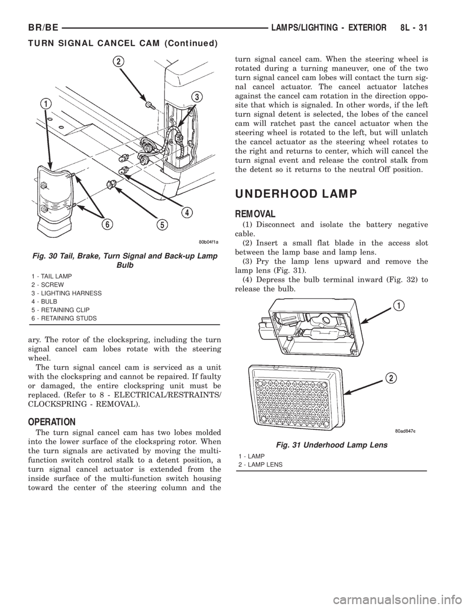
lamp lens (Fig. 31).
(4) Depress the bulb terminal inward (Fig. 32) to
release the bulb.
Fig. 30 Tail, Brake, Turn Signal and Back-up Lamp
Bulb
1 - TAIL LAMP
2 - SCREW
3 - LIGHTING HARNESS
4 - BULB
5 - RETAINING CLIP
6 - RETAINING STUDS
Fig. 31 Underhood Lamp Lens
1 - LAMP
2 - LAMP LENS
BR/BELAMPS/LIGHTING - EXTERIOR 8L - 31
TURN SIGNAL CANCEL CAM (Continued)
Page 735 of 2889
OPERATION
The wiper arms are designed to mechanically
transmit the motion from the wiper pivots to the
wiper blades. The wiper arm must be properly
indexed to the wiper pivot in order to maintain the
proper wiper blade travel on the glass. The socket
formation with internal serrations in the wiper arm
pivot end interlocks with the serrations on the outer
circumference of the wiper pivot driver, allowing pos-
itive engagement and finite adjustment of this con-
nection. The latch plate on the underside of the
wiper arm pivot end locks the wiper arm to the wiper
pivot when in its installed position and, when in its
unlocked position, also serves as a blocker to hold the
spring-loaded wiper arm off of the glass to facilitate
removal and installation. The spring-loaded wiper
arm hinge controls the down-force applied through
the tip of the wiper arm to the wiper blade on the
glass. The hook formation on the tip of the wiper arm
provides a cradle for securing and latching the wiper
blade pivot block to the wiper arm.
REMOVAL
(1) Unlatch and open the hood.
(2) Lift the wiper arm far enough to raise the
wiper blade off of the glass and permit the wiper arm
latch plate to be pulled out to its holding position,
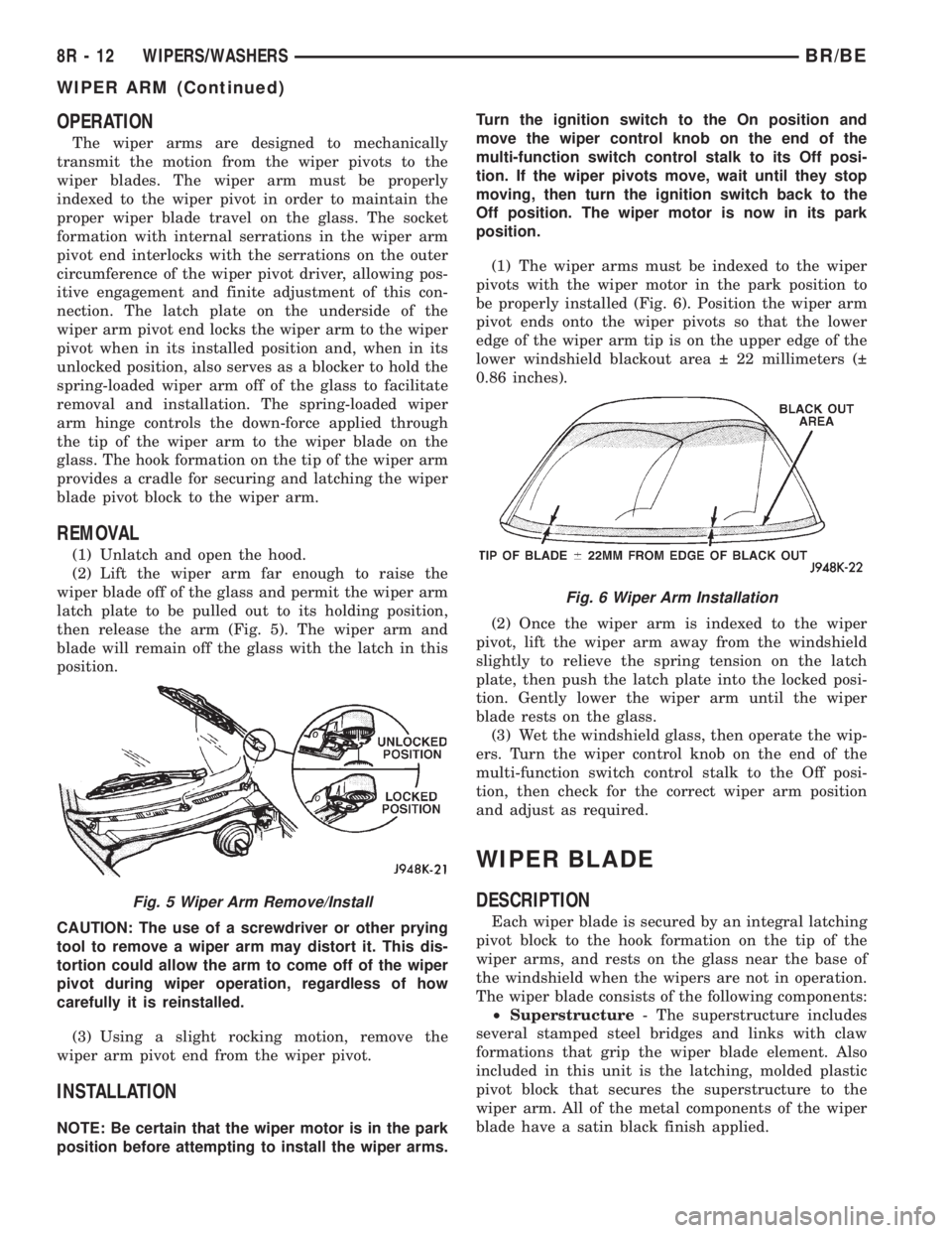
then release the arm (Fig. 5). The wiper arm and
blade will remain off the glass with the latch in this
position.
CAUTION: The use of a screwdriver or other prying
tool to remove a wiper arm may distort it. This dis-
tortion could allow the arm to come off of the wiper
pivot during wiper operation, regardless of how
carefully it is reinstalled.
(3) Using a slight rocking motion, remove the
wiper arm pivot end from the wiper pivot.
INSTALLATION
NOTE: Be certain that the wiper motor is in the park
position before attempting to install the wiper arms.Turn the ignition switch to the On position and
move the wiper control knob on the end of the
multi-function switch control stalk to its Off posi-
tion. If the wiper pivots move, wait until they stop
moving, then turn the ignition switch back to the
Off position. The wiper motor is now in its park
position.
(1) The wiper arms must be indexed to the wiper
pivots with the wiper motor in the park position to
be properly installed (Fig. 6). Position the wiper arm
pivot ends onto the wiper pivots so that the lower
edge of the wiper arm tip is on the upper edge of the
lower windshield blackout area 22 millimeters (
0.86 inches).
(2) Once the wiper arm is indexed to the wiper
pivot, lift the wiper arm away from the windshield
slightly to relieve the spring tension on the latch
plate, then push the latch plate into the locked posi-
tion. Gently lower the wiper arm until the wiper
blade rests on the glass.
(3) Wet the windshield glass, then operate the wip-
ers. Turn the wiper control knob on the end of the
multi-function switch control stalk to the Off posi-
tion, then check for the correct wiper arm position
and adjust as required.
WIPER BLADE
DESCRIPTION
Each wiper blade is secured by an integral latching
pivot block to the hook formation on the tip of the
wiper arms, and rests on the glass near the base of
the windshield when the wipers are not in operation.
The wiper blade consists of the following components:
²Superstructure- The superstructure includes
several stamped steel bridges and links with claw
formations that grip the wiper blade element. Also
included in this unit is the latching, molded plastic
pivot block that secures the superstructure to the
wiper arm. All of the metal components of the wiper
blade have a satin black finish applied.
Fig. 5 Wiper Arm Remove/Install
Fig. 6 Wiper Arm Installation
8R - 12 WIPERS/WASHERSBR/BE
WIPER ARM (Continued)
Page 2664 of 2889
ROOF JOINT MOLDING
REMOVAL
(1) Warm the roof joint molding and roof panel to
approximately 38ÉC (100ÉF) using a suitable heat
lamp or heat gun.
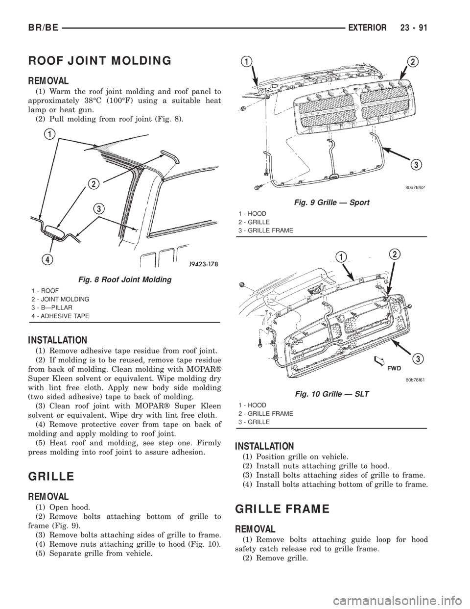
(2) Pull molding from roof joint (Fig. 8).
INSTALLATION
(1) Remove adhesive tape residue from roof joint.
(2) If molding is to be reused, remove tape residue
from back of molding. Clean molding with MOPARž
Super Kleen solvent or equivalent. Wipe molding dry
with lint free cloth. Apply new body side molding
(two sided adhesive) tape to back of molding.
(3) Clean roof joint with MOPARž Super Kleen
solvent or equivalent. Wipe dry with lint free cloth.
(4) Remove protective cover from tape on back of
molding and apply molding to roof joint.
(5) Heat roof and molding, see step one. Firmly
press molding into roof joint to assure adhesion.
GRILLE
REMOVAL
(1) Open hood.
(2) Remove bolts attaching bottom of grille to
frame (Fig. 9).
(3) Remove bolts attaching sides of grille to frame.
(4) Remove nuts attaching grille to hood (Fig. 10).
(5) Separate grille from vehicle.
INSTALLATION
(1) Position grille on vehicle.
(2) Install nuts attaching grille to hood.
(3) Install bolts attaching sides of grille to frame.
(4) Install bolts attaching bottom of grille to frame.
GRILLE FRAME
REMOVAL
(1) Remove bolts attaching guide loop for hood
safety catch release rod to grille frame.
(2) Remove grille.
Fig. 8 Roof Joint Molding
1 - ROOF
2 - JOINT MOLDING
3 - BÐPILLAR
4 - ADHESIVE TAPE
Fig. 9 Grille Ð Sport
1 - HOOD
2 - GRILLE
3 - GRILLE FRAME
Fig. 10 Grille Ð SLT
1 - HOOD
2 - GRILLE FRAME
3 - GRILLE
BR/BEEXTERIOR 23 - 91
Page 2665 of 2889
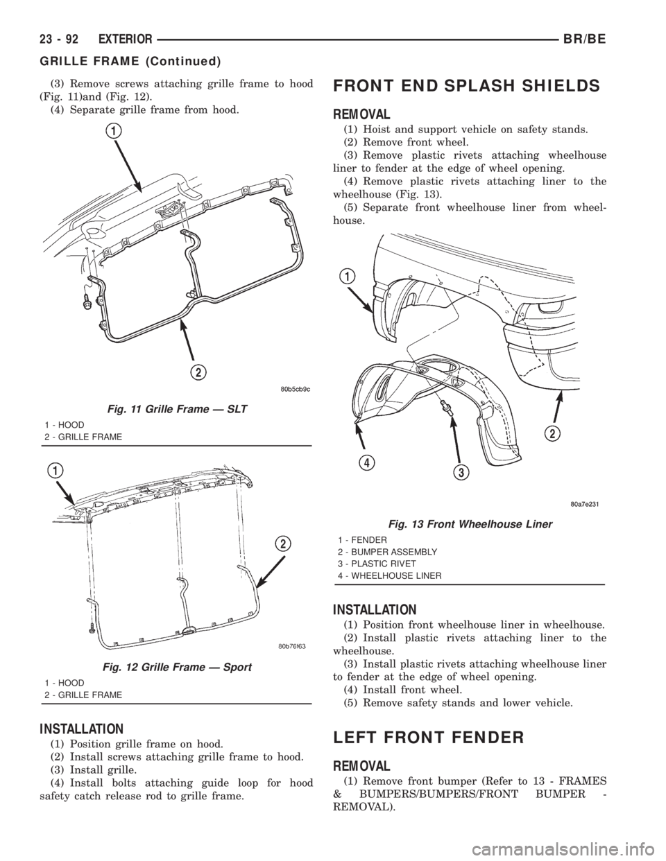
(3) Remove screws attaching grille frame to hood
(Fig. 11)and (Fig. 12).
(4) Separate grille frame from hood.
INSTALLATION
(1) Position grille frame on hood.
(2) Install screws attaching grille frame to hood.
(3) Install grille.
(4) Install bolts attaching guide loop for hood
safety catch release rod to grille frame.
FRONT END SPLASH SHIELDS
REMOVAL
(1) Hoist and support vehicle on safety stands.
(2) Remove front wheel.
(3) Remove plastic rivets attaching wheelhouse
liner to fender at the edge of wheel opening.
(4) Remove plastic rivets attaching liner to the
wheelhouse (Fig. 13).
(5) Separate front wheelhouse liner from wheel-
house.
INSTALLATION
(1) Position front wheelhouse liner in wheelhouse.
(2) Install plastic rivets attaching liner to the
wheelhouse.
(3) Install plastic rivets attaching wheelhouse liner
to fender at the edge of wheel opening.
(4) Install front wheel.
(5) Remove safety stands and lower vehicle.
LEFT FRONT FENDER
REMOVAL
(1) Remove front bumper (Refer to 13 - FRAMES
& BUMPERS/BUMPERS/FRONT BUMPER -
REMOVAL).
Fig. 11 Grille Frame Ð SLT
1 - HOOD
2 - GRILLE FRAME
Fig. 12 Grille Frame Ð Sport
1 - HOOD
2 - GRILLE FRAME
Fig. 13 Front Wheelhouse Liner
1 - FENDER
2 - BUMPER ASSEMBLY
3 - PLASTIC RIVET
4 - WHEELHOUSE LINER
23 - 92 EXTERIORBR/BE
GRILLE FRAME (Continued)
Page 2672 of 2889
HOOD
TABLE OF CONTENTS
page page
HINGE
REMOVAL..............................99
INSTALLATION...........................99
HOOD
REMOVAL.............................100
INSTALLATION..........................100
ADJUSTMENTS.........................100
LATCH
REMOVAL.............................100
INSTALLATION..........................100
ADJUSTMENTS.........................100
LATCH RELEASE CABLE
REMOVAL.............................101INSTALLATION..........................101
LATCH STRIKER
REMOVAL.............................102
INSTALLATION..........................102
ADJUSTMENTS.........................102
SAFETY LATCH
REMOVAL.............................102
INSTALLATION..........................102
SILENCER PAD
REMOVAL.............................103
INSTALLATION..........................103
HINGE
REMOVAL
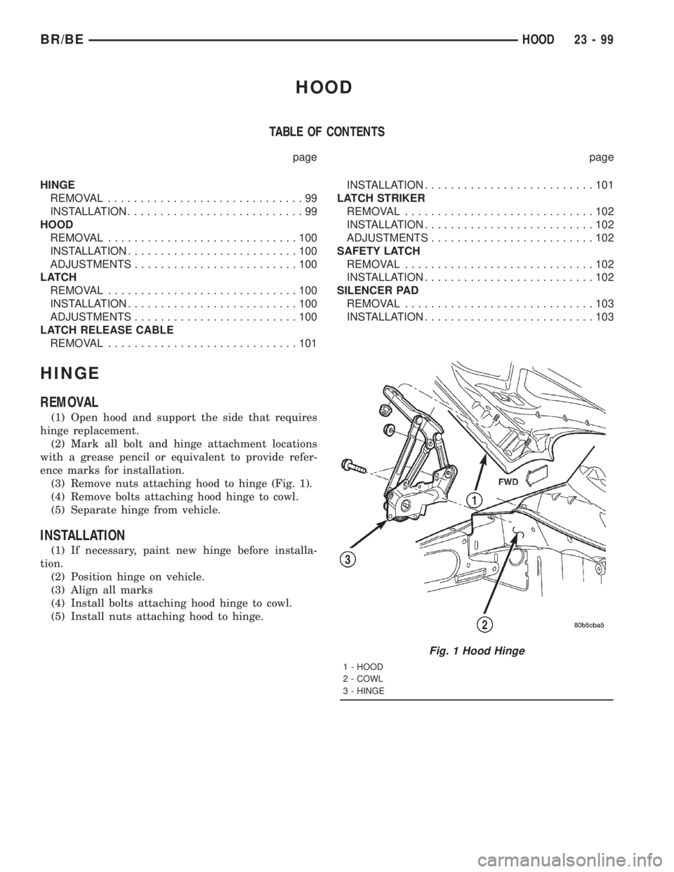
(1) Open hood and support the side that requires
hinge replacement.
(2) Mark all bolt and hinge attachment locations
with a grease pencil or equivalent to provide refer-
ence marks for installation.
(3) Remove nuts attaching hood to hinge (Fig. 1).
(4) Remove bolts attaching hood hinge to cowl.
(5) Separate hinge from vehicle.
INSTALLATION
(1) If necessary, paint new hinge before installa-
tion.
(2) Position hinge on vehicle.
(3) Align all marks
(4) Install bolts attaching hood hinge to cowl.
(5) Install nuts attaching hood to hinge.
Fig. 1 Hood Hinge
1 - HOOD
2 - COWL
3 - HINGE
BR/BEHOOD 23 - 99
Page 2673 of 2889
HOOD
REMOVAL
(1) Disconnect the under hood lamp wire connec-
tor.
(2) Disconnect the air temperature sensor wire
connector, if equipped.
(3) Mark all bolt and hinge attachment locations
with a grease pencil or equivalent to provide refer-
ence marks for installation.
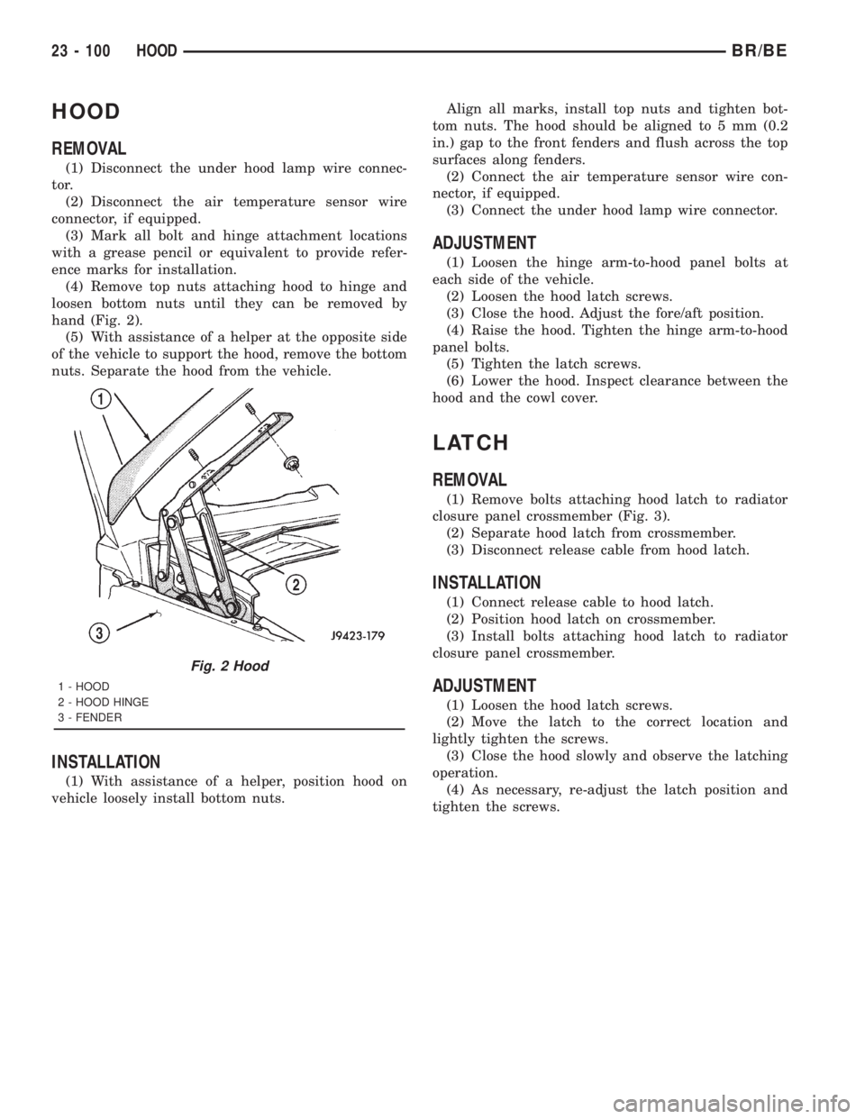
(4) Remove top nuts attaching hood to hinge and
loosen bottom nuts until they can be removed by
hand (Fig. 2).
(5) With assistance of a helper at the opposite side
of the vehicle to support the hood, remove the bottom
nuts. Separate the hood from the vehicle.
INSTALLATION
(1) With assistance of a helper, position hood on
vehicle loosely install bottom nuts.Align all marks, install top nuts and tighten bot-
tom nuts. The hood should be aligned to 5 mm (0.2
in.) gap to the front fenders and flush across the top
surfaces along fenders.
(2) Connect the air temperature sensor wire con-
nector, if equipped.
(3) Connect the under hood lamp wire connector.
ADJUSTMENT
(1) Loosen the hinge arm-to-hood panel bolts at
each side of the vehicle.
(2) Loosen the hood latch screws.
(3) Close the hood. Adjust the fore/aft position.
(4) Raise the hood. Tighten the hinge arm-to-hood
panel bolts.
(5) Tighten the latch screws.
(6) Lower the hood. Inspect clearance between the
hood and the cowl cover.
LATCH
REMOVAL
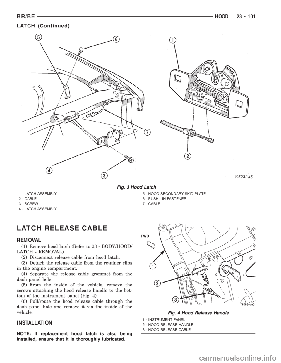
(1) Remove bolts attaching hood latch to radiator
closure panel crossmember (Fig. 3).
(2) Separate hood latch from crossmember.
(3) Disconnect release cable from hood latch.
INSTALLATION
(1) Connect release cable to hood latch.
(2) Position hood latch on crossmember.
(3) Install bolts attaching hood latch to radiator
closure panel crossmember.
ADJUSTMENT
(1) Loosen the hood latch screws.
(2) Move the latch to the correct location and
lightly tighten the screws.
(3) Close the hood slowly and observe the latching
operation.
(4) As necessary, re-adjust the latch position and
tighten the screws.
Fig. 2 Hood
1 - HOOD
2 - HOOD HINGE
3 - FENDER
23 - 100 HOODBR/BE
Page 2674 of 2889
LATCH RELEASE CABLE
REMOVAL
(1) Remove hood latch (Refer to 23 - BODY/HOOD/
LATCH - REMOVAL).
(2) Disconnect release cable from hood latch.
(3) Detach the release cable from the retainer clips
in the engine compartment.
(4) Separate the release cable grommet from the
dash panel hole.
(5) From the inside of the vehicle, remove the
screws attaching the hood release handle to the bot-
tom of the instrument panel (Fig. 4).
(6) Pull/route the hood release cable through the
dash panel hole and remove it via the inside of the
vehicle.
INSTALLATION
NOTE: If replacement hood latch is also being
installed, ensure that it is thoroughly lubricated.
Fig. 3 Hood Latch
1 - LATCH ASSEMBLY
2 - CABLE
3 - SCREW
4 - LATCH ASSEMBLY5 - HOOD SECONDARY SKID PLATE
6 - PUSHÐIN FASTENER
7 - CABLE
Fig. 4 Hood Release Handle
1 - INSTRUMENT PANEL
2 - HOOD RELEASE HANDLE
3 - HOOD RELEASE CABLE
BR/BEHOOD 23 - 101
LATCH (Continued)
Page 2675 of 2889
(1) From inside the vehicle, pull/route the hood
release cable through the dash panel hole and into
the engine compartment.
(2) Install the hood release handle.
(3) Install the cable grommet in the dash panel
hole.
(4) Attach the release cable to the retainer clips in
the engine compartment.
(5) Attach release cable to hood latch.
(6) Install hood latch (Refer to 23 - BODY/HOOD/
LATCH - INSTALLATION).
(7) Test the hood latch release cable for proper
operation.
LATCH STRIKER
REMOVAL
(1) Open hood.
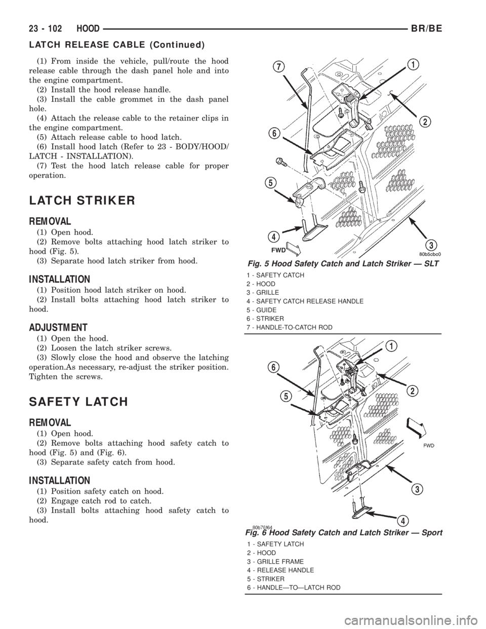
(2) Remove bolts attaching hood latch striker to
hood (Fig. 5).
(3) Separate hood latch striker from hood.
INSTALLATION
(1) Position hood latch striker on hood.
(2) Install bolts attaching hood latch striker to
hood.
ADJUSTMENT
(1) Open the hood.
(2) Loosen the latch striker screws.
(3) Slowly close the hood and observe the latching
operation.As necessary, re-adjust the striker position.
Tighten the screws.
SAFETY LATCH
REMOVAL
(1) Open hood.
(2) Remove bolts attaching hood safety catch to
hood (Fig. 5) and (Fig. 6).
(3) Separate safety catch from hood.
INSTALLATION
(1) Position safety catch on hood.
(2) Engage catch rod to catch.
(3) Install bolts attaching hood safety catch to
hood.
Fig. 5 Hood Safety Catch and Latch Striker Ð SLT
1 - SAFETY CATCH
2 - HOOD
3 - GRILLE
4 - SAFETY CATCH RELEASE HANDLE
5 - GUIDE
6 - STRIKER
7 - HANDLE-TO-CATCH ROD
Fig. 6 Hood Safety Catch and Latch Striker Ð Sport
1 - SAFETY LATCH
2 - HOOD
3 - GRILLE FRAME
4 - RELEASE HANDLE
5 - STRIKER
6 - HANDLEÐTOÐLATCH ROD
23 - 102 HOODBR/BE
LATCH RELEASE CABLE (Continued)