2001 DODGE RAM child seat
[x] Cancel search: child seatPage 676 of 2889

RESTRAINTS
TABLE OF CONTENTS
page page
RESTRAINTS
DESCRIPTION............................1
OPERATION.............................2
WARNING...............................3
DIAGNOSIS AND TESTING..................4
AIRBAG SYSTEM........................4
STANDARD PROCEDURE...................4
HANDLING NON-DEPLOYED AIRBAGS.......4
SERVICE AFTER AN AIRBAG
DEPLOYMENT..........................4
VERIFICATION TEST.....................5
SPECIAL TOOLS..........................6
AIRBAG CONTROL MODULE
DESCRIPTION............................6
OPERATION.............................6
REMOVAL...............................7
INSTALLATION............................8
CHILD TETHER
REMOVAL...............................9
INSTALLATION............................9
CLOCKSPRING
DESCRIPTION...........................10
OPERATION.............................10
STANDARD PROCEDURE..................11
CLOCKSPRING CENTERING..............11
REMOVAL..............................11
INSTALLATION...........................13
DRIVER AIRBAG
DESCRIPTION...........................14
OPERATION.............................14
REMOVAL..............................14
DISASSEMBLY...........................15
ASSEMBLY.............................17
INSTALLATION...........................18FRONT SEAT BELT & RETRACTOR
REMOVAL..............................18
INSTALLATION...........................19
FRONT SEAT BELT BUCKLE
REMOVAL..............................20
INSTALLATION...........................20
PASSENGER AIRBAG
DESCRIPTION...........................21
OPERATION.............................21
REMOVAL..............................21
INSTALLATION...........................23
PASSENGER AIRBAG ON/OFF SWITCH
DESCRIPTION...........................23
OPERATION.............................24
REMOVAL..............................24
INSTALLATION...........................25
REAR SEAT BELT & RETRACTOR
REMOVAL..............................26
INSTALLATION...........................26
REAR SEAT BELT BUCKLE
REMOVAL..............................27
INSTALLATION...........................27
SEAT BELT SWITCH
DESCRIPTION...........................28
OPERATION.............................28
DIAGNOSIS AND TESTING.................28
SEAT BELT SWITCH....................28
SEAT BELT TURNING LOOP ADJUSTER
REMOVAL..............................29
INSTALLATION...........................29
TURNING LOOP HEIGHT ADJUSTER KNOB
REMOVAL..............................30
INSTALLATION...........................30
RESTRAINTS
DESCRIPTION
A dual front airbag system is standard factory-in-
stalled safety equipment on this model. The airbag
system is a passive, inflatable, Supplemental
Restraint System (SRS) and vehicles with this equip-
ment can be readily identified by the ªSRS - AIR-
BAGº logo molded into the driver airbag trim cover
in the center of the steering wheel and also into the
passenger airbag door on the instrument panel above
the glove box (Fig. 1). Vehicles with the airbag sys-
tem can also be identified by the airbag indicator,which will illuminate in the instrument cluster for
about seven seconds as a bulb test each time the
ignition switch is turned to the On position.
The dual front airbag system consists of the follow-
ing major components, which are described in further
detail elsewhere in this service manual:
²Airbag Control Module- The Airbag Control
Module (ACM) is located on a mount on the floor
panel transmission tunnel, below the center of the
instrument panel.
²Airbag Indicator- The airbag indicator is inte-
gral to the ElectroMechanical Instrument Cluster
(EMIC), which is located on the instrument panel in
front of the driver.
BR/BERESTRAINTS 8O - 1
Page 677 of 2889

²Clockspring- The clockspring is located near
the top of the steering column, directly beneath the
steering wheel.
²Driver Airbag- The driver airbag is located in
the center of the steering wheel, beneath the driver
airbag trim cover.
²Driver Knee Blocker- The driver knee blocker
is a molded plastic structural unit secured to the
back side of and integral to the instrument panel
steering column opening cover.
²Passenger Airbag- The passenger airbag is
located on the instrument panel, beneath the passen-
ger airbag door on the instrument panel above the
glove box on the passenger side of the vehicle.
²Passenger Airbag On/Off Switch- The pas-
senger airbag on/off switch is located in a dedicated
opening in the upper right corner of the instrument
panel cluster bezel, to the right of the center panel
outlets of the climate control system.
²Passenger Knee Blocker- The passenger knee
blocker is a structural reinforcement that is integral
to and concealed within the glove box door.
The ACM and the EMIC each contain a central
processing unit and programming that allow them to
communicate with each other using the Chrysler Col-
lision Detection (CCD) data bus network. This
method of communication is used for control of the
airbag indicator on all models. (Refer to 8 - ELEC-
TRICAL/ELECTRONIC CONTROL MODULES/
COMMUNICATION - DESCRIPTION).
Hard wired circuitry connects the airbag system
components to each other through the electrical sys-
tem of the vehicle. These hard wired circuits are
integral to several wire harnesses, which are routed
throughout the vehicle and retained by many differ-
ent methods. These circuits may be connected to each
other, to the vehicle electrical system, and to the air-
bag system components through the use of a combi-
nation of soldered splices, splice block connectors,and many different types of wire harness terminal
connectors and insulators. Refer to the appropriate
wiring information. The wiring information includes
wiring diagrams, proper wire and connector repair
procedures, further details on wire harness routing
and retention, as well as pin-out and location views
for the various wire harness connectors, splices and
grounds.
OPERATION
The airbag system is referred to as a supplemental
restraint system because it was designed and is
intended to enhance the protection for the front seat
occupants of the vehicleonlywhen used in conjunc-
tion with the seat belts. It is referred to as a passive
system because the vehicle occupants are not
required to do anything to make it work. The pri-
mary passenger restraints in this or any other vehi-
cle are the standard equipment factory-installed seat
belts. Seat belts are referred to as an active restraint
because the vehicle occupants are required to physi-
cally fasten and properly adjust these restraints in
order to benefit from them. The vehicle occupants
must be wearing their seat belts in order to obtain
the maximum safety benefit from the factory-in-
stalled airbag system.
The airbag system electrical circuits are continu-
ously monitored and controlled by a microprocessor
and software contained within the Airbag Control
Module (ACM). An airbag indicator in the ElectroMe-
chanical Instrument Cluster (EMIC) lights for about
seven seconds as a bulb test each time the ignition
switch is turned to the On or Start positions. Follow-
ing the bulb test, the airbag indicator is turned on or
off by the ACM to indicate the status of the airbag
system. If the airbag indicator comes on at any time
other than during the bulb test, it indicates that
there is a problem in the airbag system electrical cir-
cuits. Such a problem may cause the airbags not to
deploy when required, or to deploy when not
required.
The clockspring on the top of the steering column
allows a continuous electrical circuit to be main-
tained between the stationary steering column and
the driver airbag inflator, which rotates with the
steering wheel. The passenger airbag on/off switch
allows the passenger side airbag to be disabled when
circumstances necessitate that a child, or an adult
with certain medical conditions be placed in the front
passenger seating position. Refer to the owner's man-
ual in the vehicle glove box for specific recommenda-
tions concerning the specific circumstances where the
passenger airbag on/off switch should be used to dis-
able the passenger airbag.
Fig. 1 SRS Logo
8O - 2 RESTRAINTSBR/BE
RESTRAINTS (Continued)
Page 684 of 2889

CHILD TETHER
REMOVAL
Standard cab models have two child tether anchors
secured near the top of the cab back panel. Club cab
and quad cab models have three child tethers
secured near the top of the cab back panel.
WARNING: DURING AND FOLLOWING ANY SEAT
BELT SERVICE, CAREFULLY INSPECT ALL SEAT
BELTS, BUCKLES, MOUNTING HARDWARE, AND
RETRACTORS FOR PROPER INSTALLATION,
OPERATION, OR DAMAGE. REPLACE ANY BELT
THAT IS CUT, FRAYED, OR TORN. STRAIGHTEN
ANY BELT THAT IS TWISTED. TIGHTEN ANY
LOOSE FASTENERS. REPLACE ANY BELT THAT
HAS A DAMAGED OR INOPERATIVE BUCKLE OR
RETRACTOR. REPLACE ANY BELT THAT HAS A
BENT OR DAMAGED LATCH PLATE OR ANCHOR
PLATE. NEVER ATTEMPT TO REPAIR A SEAT BELT
COMPONENT. ALWAYS REPLACE DAMAGED OR
FAULTY SEAT BELT COMPONENTS WITH THE COR-
RECT, NEW AND UNUSED REPLACEMENT PARTS
LISTED IN THE MOPAR PARTS CATALOG.
(1) Remove the trim from the inside of the cab
back panel. (Refer to 23 - BODY/INTERIOR/REAR
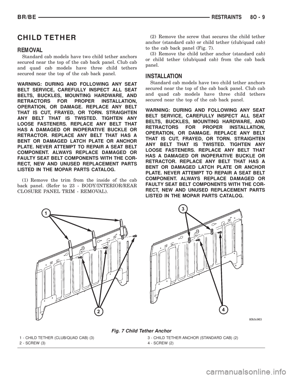
CLOSURE PANEL TRIM - REMOVAL).(2) Remove the screw that secures the child tether
anchor (standard cab) or child tether (club/quad cab)
to the cab back panel (Fig. 7).
(3) Remove the child tether anchor (standard cab)
or child tether (club/quad cab) from the cab back
panel.
INSTALLATION
Standard cab models have two child tether anchors
secured near the top of the cab back panel. Club cab
and quad cab models have three child tethers
secured near the top of the cab back panel.
WARNING: DURING AND FOLLOWING ANY SEAT
BELT SERVICE, CAREFULLY INSPECT ALL SEAT
BELTS, BUCKLES, MOUNTING HARDWARE, AND
RETRACTORS FOR PROPER INSTALLATION,
OPERATION, OR DAMAGE. REPLACE ANY BELT
THAT IS CUT, FRAYED, OR TORN. STRAIGHTEN
ANY BELT THAT IS TWISTED. TIGHTEN ANY
LOOSE FASTENERS. REPLACE ANY BELT THAT
HAS A DAMAGED OR INOPERATIVE BUCKLE OR
RETRACTOR. REPLACE ANY BELT THAT HAS A
BENT OR DAMAGED LATCH PLATE OR ANCHOR
PLATE. NEVER ATTEMPT TO REPAIR A SEAT BELT
COMPONENT. ALWAYS REPLACE DAMAGED OR
FAULTY SEAT BELT COMPONENTS WITH THE COR-
RECT, NEW AND UNUSED REPLACEMENT PARTS
LISTED IN THE MOPAR PARTS CATALOG.
Fig. 7 Child Tether Anchor
1 - CHILD TETHER (CLUB/QUAD CAB) (3)
2 - SCREW (3)3 - CHILD TETHER ANCHOR (STANDARD CAB) (2)
4 - SCREW (2)
BR/BERESTRAINTS 8O - 9
Page 2854 of 2889

CENTER HIGH MOUNTED STOP LAMP -
INSTALLATION........................8L-6
CENTER HIGH MOUNTED STOP LAMP -
REMOVAL...........................8L-6
CENTER HIGH MOUNTED STOP LAMP
UNIT - INSTALLATION..................8L-6
CENTER HIGH MOUNTED STOP LAMP
UNIT - REMOVAL.....................8L-6
CENTER SEAT ARMREST/CONSOLE -
INSTALLATION......................23-132
CENTER SEAT ARMREST/CONSOLE -
REMOVAL.........................23-132
CENTER SEAT ARMREST/LATCH COVER -
INSTALLATION......................23-132
CENTER SEAT ARMREST/LATCH COVER -
REMOVAL.........................23-132
CENTERING - STANDARD PROCEDURE,
CLOCKSPRING......................8O-11
CENTRAL TIMER MODULE - DIAGNOSIS
AND TESTING........................8E-4
CERTIFICATION LABEL - DESCRIPTION,
VEHICLE SAFETY..................Intro.-12
CHAIN COVER(S) - INSTALLATION,
TIMING BELT..........9-113,9-169,9-226,9-56
CHAIN COVER(S) - REMOVAL, TIMING
BELT ................9-113,9-169,9-225,9-56
CHAIN STRETCH - INSPECTION,
MEASURING TIMING....9-114,9-170,9-227,9-58
CHANNEL - INSTALLATION, GLASS RUN . . 23-70
CHANNEL - REMOVAL, GLASS RUN......23-70
CHARGE - STANDARD PROCEDURE,
REFRIGERANT SYSTEM...............24-46
CHARGE AIR COOLER AND PLUMBING -
CLEANING..........................11-18
CHARGE AIR COOLER AND PLUMBING -
DESCRIPTION.......................11-17
CHARGE AIR COOLER AND PLUMBING -
INSPECTION........................11-18
CHARGE AIR COOLER AND PLUMBING -
INSTALLATION.......................11-18
CHARGE AIR COOLER AND PLUMBING -
OPERATION.........................11-17
CHARGE AIR COOLER AND PLUMBING -
REMOVAL..........................11-17
CHARGING - DESCRIPTION.............8F-27
CHARGING - OPERATION..............8F-27
CHARGING - STANDARD PROCEDURE,
BATTERY............................8F-9
CHARGING SYSTEM - DIAGNOSIS AND
TESTING...........................8F-27
CHART, SPECIFICATIONS - TORQUE........5-3
CHART, SPECIFICATIONS -
TORQUE.............19-19,19-39,19-41,19-9
CHART, SPECIFICATIONS -
TORQUE.....................2-15,2-27,2-8
CHART, SPECIFICATIONS - TORQUE......22-11
CHARTS - DIAGNOSIS AND TESTING,
DIAGNOSIS......21-149,21-320,21-492,21-663
CHARTS - DIAGNOSIS AND TESTING,
SMOKE DIAGNOSIS...................9-234
CHASSIS ADAPTER BRACKET -
INSTALLATION, CAB...................13-9
CHASSIS ADAPTER BRACKET -
REMOVAL, CAB.......................13-9
CHECK - INSTALLATION...............23-78
CHECK - REMOVAL...................23-78
CHECK - STANDARD PROCEDURE,
COOLANT LEVEL......................7-16
CHECK - STANDARD PROCEDURE, FLUID
LEVEL..........21-199,21-370,21-545,21-715
CHECK - STANDARD PROCEDURE, OIL
PUMP VOLUME . . . 21-209,21-379,21-554,21-724
CHECK CABLE - INSTALLATION.........23-63
CHECK CABLE - REMOVAL.............23-62
CHECK GAUGES INDICATOR -
DESCRIPTION.......................8J-17
CHECK GAUGES INDICATOR -
OPERATION.........................8J-17
CHECK OUT - STANDARD PROCEDURE,
OWNER............................30-22
CHECK VALVE - DESCRIPTION, ONE WAY . 25-30
CHECK VALVE - DESCRIPTION, VACUUM
. . 24-28
CHECK VALVE - DIAGNOSIS AND
TESTING, ONE-WAY
..................25-30
CHECK VALVE - INSTALLATION, ONE
WAY
...............................25-30
CHECK VALVE - INSTALLATION, VACUUM
. 24-29
CHECK VALVE - OPERATION, ONE WAY
. . . 25-30CHECK VALVE - OPERATION, VACUUM....24-28
CHECK VALVE - REMOVAL, ONE WAY....25-30
CHECK VALVE - REMOVAL, VACUUM.....24-29
CHECKING BATTERY ELECTROLYTE
LEVEL - STANDARD PROCEDURE.........8F-8
CHECKING TRANSMISSION CLUTCH AND
BAND OPERATION - DIAGNOSIS AND
TESTING, AIR................21-147,21-318
CHECKS - DIAGNOSIS AND TESTING,
PRELIMINARY.........................7-4
CHILD TETHER - INSTALLATION..........8O-9
CHILD TETHER - REMOVAL.............8O-9
CHIME WARNING SYSTEM -
DESCRIPTION........................8B-1
CHIME WARNING SYSTEM - DIAGNOSIS
AND TESTING........................8B-2
CHIME WARNING SYSTEM - OPERATION . . . 8B-1
CHOKE RELAY - DESCRIPTION, RADIO....8A-8
CHOKE RELAY - DIAGNOSIS AND
TESTING, RADIO......................8A-8
CHOKE RELAY - INSTALLATION, RADIO....8A-9
CHOKE RELAY - OPERATION, RADIO......8A-8
CHOKE RELAY - REMOVAL, RADIO.......8A-9
CIGAR LIGHTER - DIAGNOSIS &
TESTING.........................8W-97-2
CIGAR LIGHTER OUTLET - DESCRIPTION . 8W-97-2
CIGAR LIGHTER OUTLET -
INSTALLATION....................8W-97-3
CIGAR LIGHTER OUTLET - OPERATION . 8W-97-2
CIGAR LIGHTER OUTLET - REMOVAL....8W-97-3
CIRCUIT ACTUATION TEST MODE -
DESCRIPTION........................25-1
CIRCUIT BREAKER - DESCRIPTION....8W-97-4
CIRCUIT BREAKER - DIAGNOSIS &
TESTING.........................8W-97-4
CIRCUIT SENSE - DESCRIPTION,
IGNITION...........................8E-17
CIRCUIT SENSE - OPERATION, IGNITION . . 8E-19
CIRCUITS - DIESEL - OPERATION,
NON-MONITORED....................25-23
CIRCUITS - GAS ENGINES - OPERATION,
NON-MONITORED....................25-22
CLAMPS - DESCRIPTION, HOSE...........7-2
CLAMPS - OPERATION, HOSE.............7-2
CLASSIFICATION OF LUBRICANTS -
STANDARD PROCEDURE.................0-3
CLEANER ELEMENT - INSTALLATION,
AIR ...............................9-245
CLEANER ELEMENT - REMOVAL, AIR.....9-244
CLEANING AND INSPECTION, OIL
COOLER & LINES....................9-296
CLEANING, APPEARANCE TIPS..........30-21
CLEANING/REVERSE FLUSHING -
STANDARD PROCEDURE, COOLING
SYSTEM............................7-16
CLEARANCE - STANDARD PROCEDURE,
CONNECTING ROD BEARING AND
CRANKSHAFT JOURNAL...............9-274
CLEARANCE - STANDARD PROCEDURE,
MAIN BEARING......................9-275
CLEARANCE LAMP - INSTALLATION.......8L-6
CLEARANCE LAMP - REMOVAL..........8L-6
CLOCKSPRING - DESCRIPTION.........8O-10
CLOCKSPRING - INSTALLATION.........8O-13
CLOCKSPRING - OPERATION...........8O-10
CLOCKSPRING - REMOVAL............8O-11
CLOCKSPRING CENTERING - STANDARD
PROCEDURE........................8O-11
CLOSURE PANEL TRIM - INSTALLATION,
REAR.............................23-121
CLOSURE PANEL TRIM - REMOVAL,
REAR.............................23-120
CLUB/QUAD CAB - INSTALLATION.......8O-20
CLUB/QUAD CAB - REMOVAL...........8O-19
CLUSTER - ASSEMBLY, INSTRUMENT....8J-13
CLUSTER - DESCRIPTION, INSTRUMENT . . . 8J-2
CLUSTER - DIAGNOSIS AND TESTING,
INSTRUMENT........................8J-6
CLUSTER - DISASSEMBLY, INSTRUMENT . . 8J-11
CLUSTER - INSTALLATION, INSTRUMENT . 8J-14
CLUSTER - OPERATION, INSTRUMENT.....8J-3
CLUSTER - REMOVAL, INSTRUMENT
.....8J-10
CLUSTER BEZEL - INSTALLATION
.......23-110
CLUSTER BEZEL - REMOVAL
..........23-109
CLUTCH - 3.9L/5.2L/5.9L/8.0L -
DESCRIPTION, FAN DRIVE VISCOUS
......7-56
CLUTCH - 3.9L/5.2L/5.9L/8.0L -
OPERATION, FAN DRIVE VISCOUS
........7-56CLUTCH - 5.9L DIESEL - DESCRIPTION,
FAN DRIVE VISCOUS...................7-57
CLUTCH - 5.9L DIESEL - OPERATION,
FAN DRIVE VISCOUS...................7-57
CLUTCH - ASSEMBLY, FRONT . . . 21-206,21-376,
21-550,21-721
CLUTCH - ASSEMBLY, REAR....21-248,21-419,
21-593,21-766
CLUTCH - CLEANING, REAR....21-247,21-418,
21-593,21-765
CLUTCH - DESCRIPTION.................6-1
CLUTCH - DESCRIPTION, A/C
COMPRESSOR.......................24-13
CLUTCH - DESCRIPTION, FRONT . 21-202,21-373,
21-548,21-718
CLUTCH - DESCRIPTION, OVERDRIVE . . . 21-214,
21-385,21-560,21-731
CLUTCH - DESCRIPTION, REAR . . 21-246,21-417,
21-591,21-764
CLUTCH - DIAGNOSTIC AND TESTING......6-2
CLUTCH - DISASSEMBLY, FRONT......21-202,
21-373,21-549,21-719
CLUTCH - DISASSEMBLY, REAR . 21-247,21-418,
21-592,21-765
CLUTCH - INSPECTION, A/C
COMPRESSOR.......................24-16
CLUTCH - INSPECTION, FRONT . . 21-205,21-376,
21-550,21-721
CLUTCH - INSPECTION, REAR . . . 21-248,21-419,
21-593,21-765
CLUTCH - INSTALLATION, A/C
COMPRESSOR.......................24-16
CLUTCH - OPERATION....................6-1
CLUTCH - OPERATION, A/C
COMPRESSOR.......................24-13
CLUTCH - OPERATION, FRONT . . 21-202,21-373,
21-548,21-718
CLUTCH - OPERATION, OVERDRIVE....21-214,
21-385,21-560,21-731
CLUTCH - OPERATION, REAR . . . 21-246,21-417,
21-592,21-764
CLUTCH - REMOVAL, A/C COMPRESSOR . . 24-14
CLUTCH - SPECIFICATIONS...............6-7
CLUTCH - WARNING....................6-2
CLUTCH AND BAND OPERATION -
DIAGNOSIS AND TESTING, AIR
CHECKING TRANSMISSION......21-147,21-318
CLUTCH AND BAND OPERATION -
DIAGNOSIS AND TESTING, AIR
TESTING TRANSMISSION.......21-490,21-661
CLUTCH BREAK-IN - STANDARD
PROCEDURE, A/C COMPRESSOR........24-13
CLUTCH CAM/OVERDRIVE PISTON
RETAINER - ASSEMBLY,
OVERRUNNING . . . 21-236,21-406,21-581,21-752
CLUTCH CAM/OVERDRIVE PISTON
RETAINER - CLEANING, OVERRUNNING . 21-236,
21-406,21-580,21-752
CLUTCH CAM/OVERDRIVE PISTON
RETAINER - DESCRIPTION,
OVERRUNNING . . . 21-235,21-405,21-580,21-751
CLUTCH CAM/OVERDRIVE PISTON
RETAINER - DISASSEMBLY,
OVERRUNNING . . . 21-235,21-405,21-580,21-751
CLUTCH CAM/OVERDRIVE PISTON
RETAINER - INSPECTION,
OVERRUNNING . . . 21-236,21-406,21-580,21-752
CLUTCH CAM/OVERDRIVE PISTON
RETAINER - OPERATION,
OVERRUNNING . . . 21-235,21-405,21-580,21-751
CLUTCH COIL - DIAGNOSIS AND
TESTING, A/C COMPRESSOR...........24-13
CLUTCH DISC - DESCRIPTION............6-7
CLUTCH DISC - INSTALLATION............6-9
CLUTCH DISC - OPERATION..............6-8
CLUTCH DISC - REMOVAL...............6-8
CLUTCH HOUSING - DIAGNOSIS AND
TESTING............................6-11
CLUTCH HOUSING - INSTALLATION.......6-13
CLUTCH HOUSING - REMOVAL...........6-13
CLUTCH PEDAL - INSTALLATION
.........6-19
CLUTCH PEDAL - REMOVAL
.............6-18
CLUTCH PEDAL POSITION SWITCH -
DESCRIPTION
........................6-22
CLUTCH PEDAL POSITION SWITCH -
OPERATION
..........................6-22
CLUTCH RELAY - DESCRIPTION, A/C
COMPRESSOR
.......................24-17
BR/BEINDEX 7
Description Group-Page Description Group-Page Description Group-Page