2001 DODGE RAM window
[x] Cancel search: windowPage 7 of 2889

FASTENER USAGE
DESCRIPTION - FASTENER USAGE
WARNING: USE OF AN INCORRECT FASTENER
MAY RESULT IN COMPONENT DAMAGE OR PER-
SONAL INJURY.
Figure art, specifications and torque references in
this Service Manual are identified in metric and SAE
format.
During any maintenance or repair procedures, it is
important to salvage all fasteners (nuts, bolts, etc.)
for reassembly. If the fastener is not salvageable, a
fastener of equivalent specification must be used.
DESCRIPTION - THREADED HOLE REPAIR
Most stripped threaded holes can be repaired using
a Helicoilt. Follow the manufactures recommenda-
tions for application and repair procedures.
INTERNATIONAL VEHICLE
CONTROL & DISPLAY
SYMBOLS
DESCRIPTION - INTERNATIONAL SYMBOLS
The graphic symbols illustrated in the following
International Control and Display Symbols Chart are
used to identify various instrument controls. The
symbols correspond to the controls and displays that
are located on the instrument panel.
METRIC SYSTEM
DESCRIPTION - METRIC SYSTEM
The metric system is based on quantities of one,
ten, one hundred, one thousand and one million .
The following chart will assist in converting metric
units to equivalent English and SAE units, or vise
versa.
International Symbols
1 High Beam 13 Rear Window Washer
2 Fog Lamps 14 Fuel
3 Headlamp, Parking Lamps, Panel Lamps 15 Engine Coolant Temperature
4 Turn Warning 16 Battery Charging Condition
5 Hazard Warning 17 Engine Oil
6 Windshield Washer 18 Seat Belt
7 Windshield Wiper 19 Brake Failure
8 Windshield Wiper and Washer 20 Parking Brake
9 Windscreen Demisting and Defrosting 21 Front Hood
10 Ventilating Fan 22 Rear hood (Decklid)
11 Rear Window Defogger 23 Horn
12 Rear Window Wiper 24 Lighter
6 INTRODUCTIONBR/BE
Page 516 of 2889
HEATED SYSTEMS
TABLE OF CONTENTS
page page
HEATED MIRRORS......................... 1 HEATED SEATSYSTEM..................... 5
HEATED MIRRORS
TABLE OF CONTENTS
page page
HEATED MIRRORS
DESCRIPTION............................1
OPERATION.............................2
DIAGNOSIS AND TESTING..................2
HEATED MIRROR SYSTEM................2
MIRROR SWITCH
DESCRIPTION............................3
OPERATION.............................3DIAGNOSIS AND TESTING..................3
HEATED MIRROR SWITCH................3
HEATED MIRROR GRID
DESCRIPTION............................4
OPERATION.............................4
DIAGNOSIS AND TESTING..................0
HEATED MIRROR GRID...................4
HEATED MIRRORS
DESCRIPTION - HEATED MIRROR SYSTEM
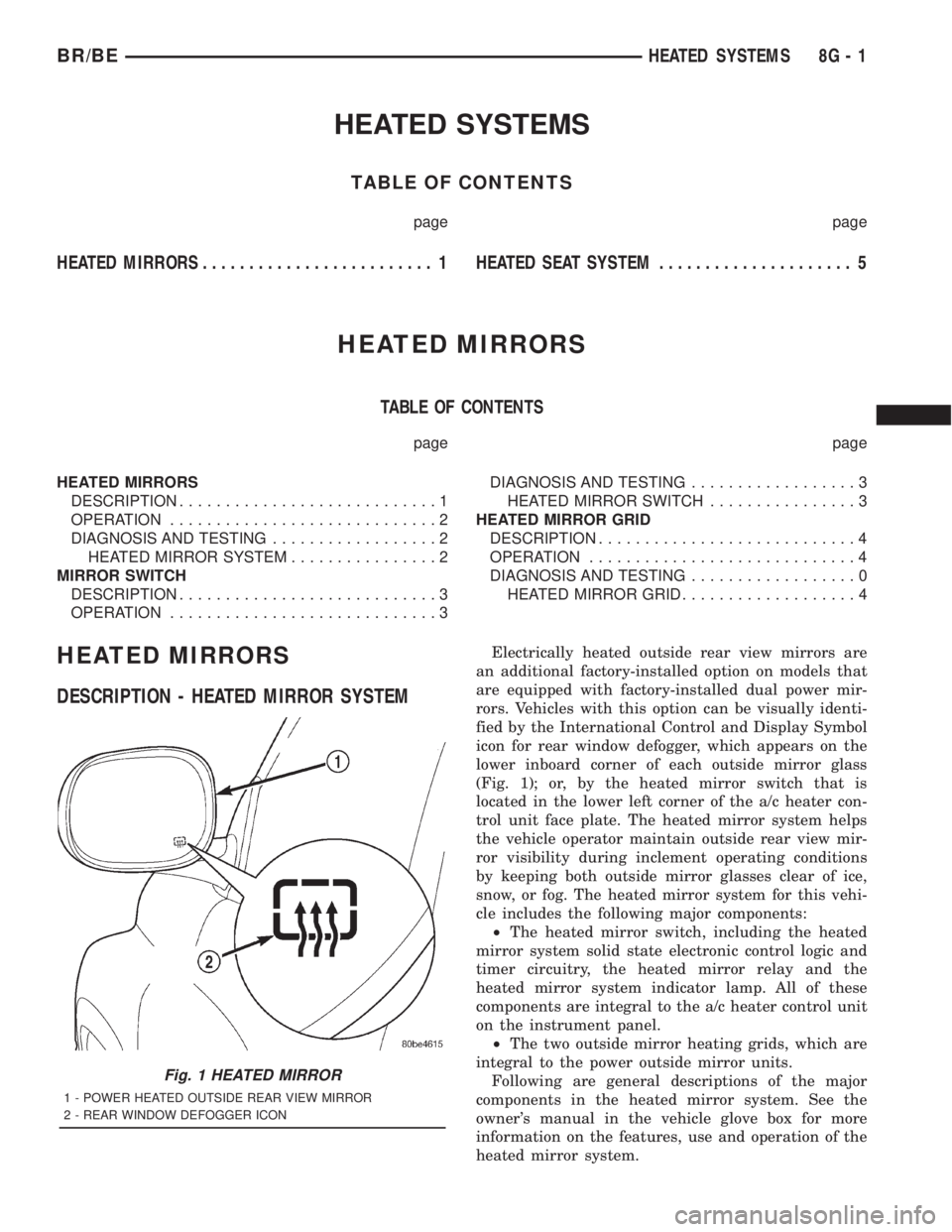
Electrically heated outside rear view mirrors are
an additional factory-installed option on models that
are equipped with factory-installed dual power mir-
rors. Vehicles with this option can be visually identi-
fied by the International Control and Display Symbol
icon for rear window defogger, which appears on the
lower inboard corner of each outside mirror glass
(Fig. 1); or, by the heated mirror switch that is
located in the lower left corner of the a/c heater con-
trol unit face plate. The heated mirror system helps
the vehicle operator maintain outside rear view mir-
ror visibility during inclement operating conditions
by keeping both outside mirror glasses clear of ice,
snow, or fog. The heated mirror system for this vehi-
cle includes the following major components:
²The heated mirror switch, including the heated
mirror system solid state electronic control logic and
timer circuitry, the heated mirror relay and the
heated mirror system indicator lamp. All of these
components are integral to the a/c heater control unit
on the instrument panel.
²The two outside mirror heating grids, which are
integral to the power outside mirror units.
Following are general descriptions of the major
components in the heated mirror system. See the
owner's manual in the vehicle glove box for more
information on the features, use and operation of the
heated mirror system.
Fig. 1 HEATED MIRROR
1 - POWER HEATED OUTSIDE REAR VIEW MIRROR
2 - REAR WINDOW DEFOGGER ICON
BR/BEHEATED SYSTEMS 8G - 1
Page 570 of 2889
DISASSEMBLY
Some of the components for the instrument cluster
used in this vehicle are serviced individually. The
serviced components include: the automatic transmis-
sion gear selector indicator, the incandescent instru-
ment cluster indicator lamp and illumination lamp
bulbs (including the integral bulb holders), the clus-
ter lens and hood unit, and the cluster housing rear
cover. The remaining components are serviced only
as a part of the cluster housing unit, which includes:
the cluster housing, the electronic circuit board unit,
the cluster overlay, the gauges, and the odometer/trip
odometer reset switch button. Following are the pro-
cedures for disassembling the serviced components
from the instrument cluster unit.
WARNING: ON VEHICLES EQUIPPED WITH AIR-
BAGS, DISABLE THE AIRBAG SYSTEM BEFORE
ATTEMPTING ANY STEERING WHEEL, STEERING
COLUMN, OR INSTRUMENT PANEL COMPONENT
DIAGNOSIS OR SERVICE. DISCONNECT AND ISO-
LATE THE BATTERY NEGATIVE (GROUND) CABLE,
THEN WAIT TWO MINUTES FOR THE AIRBAG SYS-
TEM CAPACITOR TO DISCHARGE BEFORE PER-
FORMING FURTHER DIAGNOSIS OR SERVICE. THIS
IS THE ONLY SURE WAY TO DISABLE THE AIRBAG
SYSTEM. FAILURE TO TAKE THE PROPER PRE-
CAUTIONS COULD RESULT IN ACCIDENTAL AIR-
BAG DEPLOYMENT AND POSSIBLE PERSONAL
INJURY.GEAR SELECTOR INDICATOR
(1) Disconnect and isolate the battery negative
cable.
(2) Remove the instrument cluster from the instru-
ment panel. (Refer to 8 - ELECTRICAL/INSTRU-
MENT CLUSTER - REMOVAL).
(3) Remove the steering column opening cover
from the instrument panel. (Refer to 23 - BODY/IN-
STRUMENT PANEL/STEERING COLUMN OPEN-
ING COVER - REMOVAL).
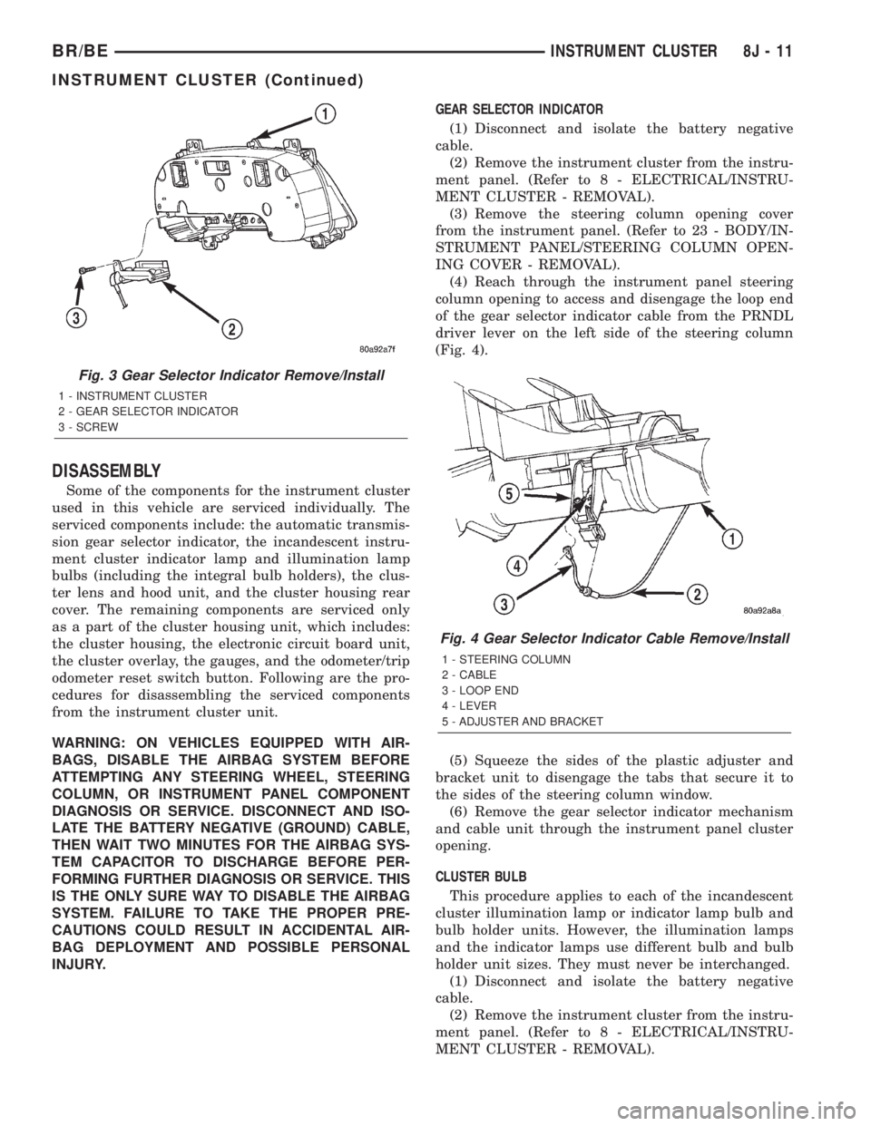
(4) Reach through the instrument panel steering
column opening to access and disengage the loop end
of the gear selector indicator cable from the PRNDL
driver lever on the left side of the steering column
(Fig. 4).
(5) Squeeze the sides of the plastic adjuster and
bracket unit to disengage the tabs that secure it to
the sides of the steering column window.
(6) Remove the gear selector indicator mechanism
and cable unit through the instrument panel cluster
opening.
CLUSTER BULB
This procedure applies to each of the incandescent
cluster illumination lamp or indicator lamp bulb and
bulb holder units. However, the illumination lamps
and the indicator lamps use different bulb and bulb
holder unit sizes. They must never be interchanged.
(1) Disconnect and isolate the battery negative
cable.
(2) Remove the instrument cluster from the instru-
ment panel. (Refer to 8 - ELECTRICAL/INSTRU-
MENT CLUSTER - REMOVAL).
Fig. 3 Gear Selector Indicator Remove/Install
1 - INSTRUMENT CLUSTER
2 - GEAR SELECTOR INDICATOR
3 - SCREW
Fig. 4 Gear Selector Indicator Cable Remove/Install
1 - STEERING COLUMN
2 - CABLE
3 - LOOP END
4 - LEVER
5 - ADJUSTER AND BRACKET
BR/BEINSTRUMENT CLUSTER 8J - 11
INSTRUMENT CLUSTER (Continued)
Page 572 of 2889
ASSEMBLY
WARNING: ON VEHICLES EQUIPPED WITH AIR-
BAGS, DISABLE THE AIRBAG SYSTEM BEFORE
ATTEMPTING ANY STEERING WHEEL, STEERING
COLUMN, OR INSTRUMENT PANEL COMPONENT
DIAGNOSIS OR SERVICE. DISCONNECT AND ISO-
LATE THE BATTERY NEGATIVE (GROUND) CABLE,
THEN WAIT TWO MINUTES FOR THE AIRBAG SYS-
TEM CAPACITOR TO DISCHARGE BEFORE PER-
FORMING FURTHER DIAGNOSIS OR SERVICE. THIS
IS THE ONLY SURE WAY TO DISABLE THE AIRBAG
SYSTEM. FAILURE TO TAKE THE PROPER PRE-
CAUTIONS COULD RESULT IN ACCIDENTAL AIR-
BAG DEPLOYMENT AND POSSIBLE PERSONAL
INJURY.
GEAR SELECTOR INDICATOR
(1) Position the gear selector indicator mechanism
and cable unit into the instrument panel cluster
opening.
(2) Route the cable through the instrument panel
and under the steering column to the PRNDL driver
lever on the left side of the steering column.
(3) Squeeze the sides of the plastic adjuster and
bracket unit and engage the tabs that secure it with
the sides of the steering column window.
(4) Engage the loop end of the gear selector indi-
cator cable onto the PRNDL driver lever on the left
side of the steering column (Fig. 4).
(5) Reinstall the instrument cluster onto the
instrument panel. (Refer to 8 - ELECTRICAL/IN-
STRUMENT CLUSTER - INSTALLATION).
(6) Confirm proper operation of the gear selector
indicator. Calibrate the indicator, if required. (Refer
to 19 - STEERING/COLUMN - INSTALLATION).
(7) Reinstall the steering column opening cover
onto the instrument panel. (Refer to 23 - BODY/IN-
STRUMENT PANEL/STEERING COLUMN OPEN-
ING COVER - INSTALLATION).
(8) Reconnect the battery negative cable.
CLUSTER BULB
This procedure applies to each of the incandescent
cluster illumination lamp or indicator lamp bulb and
bulb holder units. However, the illumination lamps
and the indicator lamps use different bulb and bulb
holder unit sizes. They must never be interchanged.
CAUTION: Be certain that any bulb and bulb holder
unit removed from the cluster electronic circuit
board is reinstalled in the correct position. Always
use the correct bulb size and type for replacement.
An incorrect bulb size or type may overheat and
cause damage to the instrument cluster, the elec-
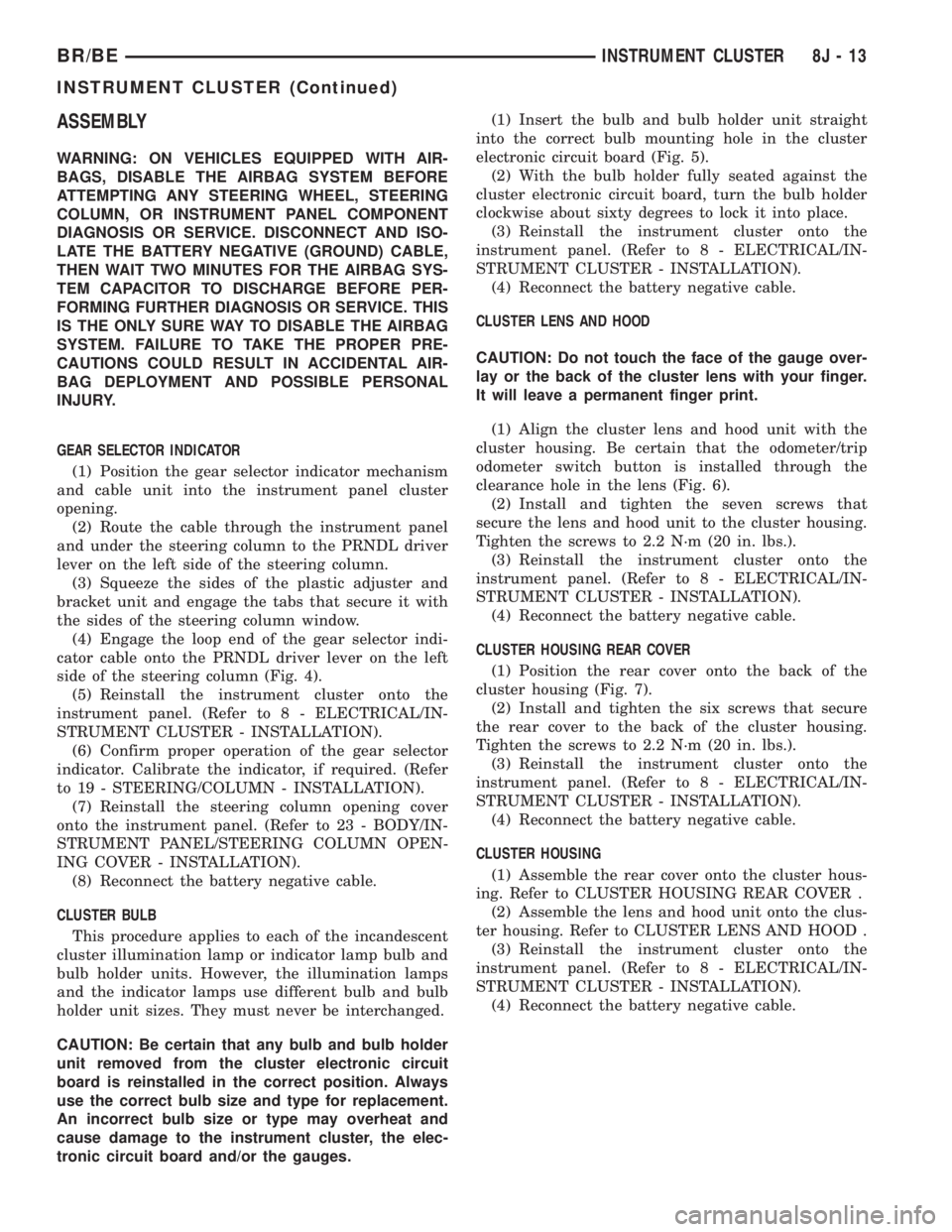
tronic circuit board and/or the gauges.(1) Insert the bulb and bulb holder unit straight
into the correct bulb mounting hole in the cluster
electronic circuit board (Fig. 5).
(2) With the bulb holder fully seated against the
cluster electronic circuit board, turn the bulb holder
clockwise about sixty degrees to lock it into place.
(3) Reinstall the instrument cluster onto the
instrument panel. (Refer to 8 - ELECTRICAL/IN-
STRUMENT CLUSTER - INSTALLATION).
(4) Reconnect the battery negative cable.
CLUSTER LENS AND HOOD
CAUTION: Do not touch the face of the gauge over-
lay or the back of the cluster lens with your finger.
It will leave a permanent finger print.
(1) Align the cluster lens and hood unit with the
cluster housing. Be certain that the odometer/trip
odometer switch button is installed through the
clearance hole in the lens (Fig. 6).
(2) Install and tighten the seven screws that
secure the lens and hood unit to the cluster housing.
Tighten the screws to 2.2 N´m (20 in. lbs.).
(3) Reinstall the instrument cluster onto the
instrument panel. (Refer to 8 - ELECTRICAL/IN-
STRUMENT CLUSTER - INSTALLATION).
(4) Reconnect the battery negative cable.
CLUSTER HOUSING REAR COVER
(1) Position the rear cover onto the back of the
cluster housing (Fig. 7).
(2) Install and tighten the six screws that secure
the rear cover to the back of the cluster housing.
Tighten the screws to 2.2 N´m (20 in. lbs.).
(3) Reinstall the instrument cluster onto the
instrument panel. (Refer to 8 - ELECTRICAL/IN-
STRUMENT CLUSTER - INSTALLATION).
(4) Reconnect the battery negative cable.
CLUSTER HOUSING
(1) Assemble the rear cover onto the cluster hous-
ing. Refer to CLUSTER HOUSING REAR COVER .
(2) Assemble the lens and hood unit onto the clus-
ter housing. Refer to CLUSTER LENS AND HOOD .
(3) Reinstall the instrument cluster onto the
instrument panel. (Refer to 8 - ELECTRICAL/IN-
STRUMENT CLUSTER - INSTALLATION).
(4) Reconnect the battery negative cable.
BR/BEINSTRUMENT CLUSTER 8J - 13
INSTRUMENT CLUSTER (Continued)
Page 580 of 2889
²More Than Full Percent Tank Full Message
- Each time the cluster receives a message from the
PCM indicating the percent tank full is more than
full, the gauge needle is moved to the far left (low)
end of the gauge scale and the low fuel indicator is
illuminated immediately. This message would indi-
cate that the fuel tank sender input to the PCM is an
open circuit.
²Message Failure- If the cluster fails to receive
a percent tank full message, it will hold the gauge
needle at the last indication until a new message is
received, or until the ignition switch is turned to the
Off position, whichever occurs first.
²Actuator Test- Each time the cluster is put
through the actuator test, the gauge needle will be
swept to several calibration points on the gauge scale
in a prescribed sequence in order to confirm the func-
tionality of the gauge and the cluster control cir-
cuitry.
The PCM continually monitors the fuel tank send-
ing unit, then sends the proper messages to the
instrument cluster. For further diagnosis of the fuel
gauge or the instrument cluster circuitry that con-
trols the gauge, (Refer to 8 - ELECTRICAL/INSTRU-
MENT CLUSTER - DIAGNOSIS AND TESTING).
For proper diagnosis of the fuel tank sending unit,
the PCM, the CCD data bus, or the message inputs
to the instrument cluster that control the fuel gauge,
a DRBIIItscan tool is required. Refer to the appro-
priate diagnostic information.
GEAR SELECTOR INDICATOR
DESCRIPTION
A mechanical automatic transmission gear selector
indicator is standard factory-installed equipment on
this model, when it is also equipped with an optional
automatic transmission. The gear selector indicator
consists of a molded black plastic housing with inte-
gral mounting tabs that is secured to the back of the
instrument cluster housing with two screws. A face
plate on the indicator housing is visible through a
rectangular cutout in the lower right corner of the
instrument cluster overlay, just below the fuel gauge.
Vehicles with a manual transmission have a block-off
plate mounted to the back of the instrument cluster
behind this cutout in the overlay, in place of the gear
selector indicator. Near the top of this face plate the
following characters are imprinted from left to right:
ªP,º ªR,º ªN,º ªD,º ª2,º and ª1.º Respectively, these
characters represent the park, reverse, neutral,
drive, second gear, and first gear positions of the
transmission gear selector lever on the steering col-
umn. Directly below each character on the face plateis a small, rectangular window, and behind these
windows is a single, movable red pointer.
The gear selector indicator graphics are white
against a black field except for the single red pointer,
making them clearly visible within the instrument
cluster in daylight. When illuminated from behind by
the panel lamps dimmer controlled cluster illumina-
tion lighting with the exterior lamps turned On, the
white graphics appear blue-green, while the red
pointer still appears red. Indicator illumination is
provided by replaceable incandescent bulb and bulb
holder units located on the instrument cluster elec-
tronic circuit board. The gear selector indicator is
available for service replacement separate from the
instrument cluster. The instrument cluster must be
removed from the instrument panel for service access
to the gear selector indicator. (Refer to 8 - ELECTRI-
CAL/INSTRUMENT CLUSTER - REMOVAL).
OPERATION
The mechanical gear selector indicator gives an
indication of the transmission gear that has been
selected with the automatic transmission gear selec-
tor lever. A red pointer appears in a window below
the character in the indicator representing the trans-
mission gear that has been selected. The small,
spring-loaded pointer moves on a track through a
trolley-like mechanism within the indicator housing.
A short length of small diameter stranded cable is
attached to one side of the pointer trolley and is
encased in a tubular plastic housing that exits the
right side of the indicator. The cable is routed
through the instrument panel and under the steering
column to the left side of the column. The looped end
of the cable is hooked over the end of the PRNDL
driver lever on the steering column gearshift mecha-
nism, and the cable housing is secured in a molded
plastic adjuster and bracket on the column housing.
When the gear selector lever is moved the PRNDL
driver lever moves, which moves the pointer through
the mechanical actuator cable. The cable adjuster
and bracket unit mounted on the steering column
housing provides a mechanical means of calibrating
the gear selector indicator mechanism. (Refer to 19 -
STEERING/COLUMN - INSTALLATION).
HIGH BEAM INDICATOR
DESCRIPTION
A high beam indicator is standard equipment on
all instrument clusters. The high beam indicator is
located near the upper edge of the instrument cluster
overlay, between the tachometer and the speedome-
ter. The high beam indicator consists of a stenciled
cutout of the International Control and Display Sym-
BR/BEINSTRUMENT CLUSTER 8J - 21
FUEL GAUGE (Continued)
Page 583 of 2889

MALFUNCTION INDICATOR
LAMP (MIL)
DESCRIPTION
A Malfunction Indicator Lamp (MIL) is standard
equipment on all instrument clusters. The MIL is
located near the lower edge of the instrument cluster
overlay, to the left of center. The MIL consists of a
stencilled cutout of the International Control and
Display Symbol icon for ªEngineº in the opaque layer
of the instrument cluster overlay. The dark outer
layer of the overlay prevents the indicator from being
clearly visible when it is not illuminated. An amber
lens behind the cutout in the opaque layer of the
overlay causes the icon to appear in amber through
the translucent outer layer of the overlay when the
indicator is illuminated from behind by a Light Emit-
ting Diode (LED) soldered onto the instrument clus-
ter electronic circuit board. The MIL is serviced as a
unit with the instrument cluster.
OPERATION
The Malfunction Indicator Lamp (MIL) gives an
indication to the vehicle operator when the Power-
train Control Module (PCM) has recorded a Diagnos-
tic Trouble Code (DTC) for an On-Board Diagnostics
II (OBDII) emissions-related circuit or component
malfunction. In addition, on models with a diesel
engine an Engine Control Module (ECM) supple-
ments the PCM, and can also record an OBDII DTC.
The MIL is controlled by a transistor on the instru-
ment cluster circuit board based upon cluster pro-
gramming and electronic messages received by the
cluster from the PCM or ECM over the Chrysler Col-
lision Detection (CCD) data bus. The MIL Light
Emitting Diode (LED) receives battery current on the
instrument cluster electronic circuit board through
the fused ignition switch output (st-run) circuit
whenever the ignition switch is in the On or Start
positions; therefore, the LED will always be off when
the ignition switch is in any position except On or
Start. The LED only illuminates when it is provided
a path to ground by the instrument cluster transis-
tor. The instrument cluster will turn on the MIL for
the following reasons:
²Bulb Test- Each time the ignition switch is
turned to the On position the indicator is illuminated
for about seven seconds as a bulb test.
²PCM Lamp-On Message- Each time the clus-
ter receives a lamp-on message from the PCM or
ECM, the indicator will be illuminated. The indicator
can be flashed on and off, or illuminated solid, as dic-
tated by the PCM/ECM message. For some DTC's, if
a problem does not recur, the PCM or ECM will send
a lamp-off message automatically. Other DTC's mayrequire that a fault be repaired and the PCM or
ECM be reset before a lamp-off message will be sent.
For more information on the PCM, the ECM, and the
DTC set and reset parameters, (Refer to 25 - EMIS-
SIONS CONTROL - OPERATION).
²Communication Error- If the cluster receives
no lamp-on message from the PCM or ECM for
twenty seconds, the MIL is illuminated by the instru-
ment cluster to indicate a loss of bus communication.
The indicator remains controlled and illuminated by
the cluster until a valid lamp-on message is received
from the PCM or ECM.
²Actuator Test- Each time the cluster is put
through the actuator test, the indicator will be
turned on during the bulb check portion of the test to
confirm the functionality of the LED and the cluster
control circuitry.
The PCM/ECM continually monitor the fuel and
emissions system circuits and sensors to decide
whether the system is in good operating condition.
The PCM/ECM then sends the proper lamp-on or
lamp-off messages to the instrument cluster. For fur-
ther diagnosis of the MIL or the instrument cluster
circuitry that controls the LED, (Refer to 8 - ELEC-
TRICAL/INSTRUMENT CLUSTER - DIAGNOSIS
AND TESTING). If the instrument cluster turns on
the MIL after the bulb test, it may indicate that a
malfunction has occurred and that the fuel and emis-
sions systems may require service. For proper diag-
nosis of the fuel and emissions systems, the PCM,
the ECM, the CCD data bus, or the message inputs
to the instrument cluster that control the MIL, a
DRBIIItscan tool is required. Refer to the appropri-
ate diagnostic information.
ODOMETER
DESCRIPTION
An odometer and trip odometer are standard
equipment in all instrument clusters. The odometer
and trip odometer information are displayed in a
common electronic Vacuum-Fluorescent Display
(VFD), which is visible through a small window cut-
out located in the left lower quadrant of the cluster
overlay. However, the odometer and trip odometer
information are not displayed simultaneously. The
trip odometer reset switch on the instrument cluster
circuit board toggles the display between odometer
and trip odometer modes by depressing the odometer/
trip odometer switch knob that extends through the
lower edge of the cluster lens, just right of the
tachometer. Both the odometer and the trip odometer
information is stored in the instrument cluster mem-
ory.
8J - 24 INSTRUMENT CLUSTERBR/BE
Page 650 of 2889
POWER SYSTEMS
TABLE OF CONTENTS
page page
POWER LOCKS............................ 1
POWER MIRRORS........................ 10POWER SEAT SYSTEM..................... 15
POWER WINDOWS........................ 23
POWER LOCKS
TABLE OF CONTENTS
page page
POWER LOCKS
DESCRIPTION............................1
OPERATION.............................3
DIAGNOSIS AND TESTING..................4
POWER LOCK SYSTEM...................4
POWER LOCK & REMOTE KEYLESS
ENTRY SYSTEM.........................4
DOOR CYLINDER LOCK SWITCH
DESCRIPTION............................5
OPERATION.............................5
DIAGNOSIS AND TESTING..................5
DOOR CYLINDER LOCK SWITCH...........5
REMOVAL...............................6
INSTALLATION............................6
POWER LOCK MOTOR
DESCRIPTION............................6OPERATION.............................6
DIAGNOSIS AND TESTING..................7
POWER LOCK MOTOR...................7
REMOTE KEYLESS ENTRY TRANSMITTER
DESCRIPTION............................7
OPERATION.............................7
DIAGNOSIS AND TESTING..................7
REMOTE KEYLESS ENTRY TRANSMITTER....7
STANDARD PROCEDURE...................8
RKE TRANSMITTER PROGRAMMING........8
RKE TRANSMITTER BATTERIES............8
POWER LOCK SWITCH
DESCRIPTION............................8
OPERATION.............................8
DIAGNOSIS AND TESTING..................8
POWER LOCK SWITCH...................8
POWER LOCKS
DESCRIPTION - POWER LOCK SYSTEM
Two different power lock systems are offered as
optional factory-installed equipment on this model.
Both power lock systems are offered only on models
that are also equipped with power windows. On mod-
els without the optional Remote Keyless Entry (RKE)
system, a base version of the Central Timer Module
(CTM) is used. In this version of the power lock sys-
tem, the power lock switches provide the only control
over the operation of the power lock motors. On mod-
els with the optional RKE system, a high-line or pre-
mium version of the CTM is used to provide many
electronic features and conveniences that are not pos-
sible with the base version CTM. In this power lock
system, the power lock motors are controlled by the
microprocessor-based high-line or premium version ofthe CTM based upon the CTM programming and
electronic message inputs received from other elec-
tronic modules in the vehicle over the Chrysler Col-
lision Detection (CCD) data bus network, Radio
Frequency (RF) inputs received from the RKE trans-
mitters, as well as many hard wired inputs.
Both versions of the power lock system include the
following major components, which are described in
further detail elsewhere in this service manual:
²Power Lock Motors- A reversible electric
motor integral to the door latch of each front door
locks or unlocks the front door latch when provided
with the appropriate electrical inputs.
²Power Lock Switches- A power lock switch
integral to the power window/lock switch unit located
near the forward end of the arm rest on each front
door trim panel allows the power door lock system to
be operated by either the driver or the front seat pas-
senger.
BR/BEPOWER SYSTEMS 8N - 1
Page 657 of 2889
the suspect transmitter does not, replace the faulty
RKE transmitter.
NOTE: Be certain to perform the RKE Transmitter
Programming procedure again following this test.
This procedure will erase the access code of the
test transmitter from the RKE receiver.
STANDARD PROCEDURE - RKE TRANSMITTER
PROGRAMMING
To program the Remote Keyless Entry (RKE)
transmitter access codes into the RKE receiver in the
high-line or premium Central Timer Module (CTM)
requires the use of a DRBIIItscan tool. Refer to the
appropriate diagnostic information.
STANDARD PROCEDURE - RKE TRANSMITTER
BATTERIES
The Remote Keyless Entry (RKE) transmitter case
snaps open and shut for battery access. To replace
the RKE transmitter batteries:
(1) Using a trim stick or a thin coin, gently pry at
the notch in the center seam of the RKE transmitter
case halves located near the key ring until the two
halves unsnap.
(2) Lift the back half of the transmitter case off of
the RKE transmitter.
(3) Remove the two batteries from the RKE trans-
mitter.
(4) Replace the two batteries with new Duracell
DL2016, or their equivalent. Be certain that the bat-
teries are installed with their polarity correctly ori-
ented.
(5) Align the two RKE transmitter case halves
with each other, and squeeze them firmly and evenly
together using hand pressure until they snap back
into place.
POWER LOCK SWITCH
DESCRIPTION
The power lock system can be controlled by a two-
way momentary switch integral to the power window
and lock switch and bezel unit on the trim panel of
each front door. Each power lock switch is illumi-
nated by a Light-Emitting Diode (LED) that is inte-
gral to the switch paddle. The LED of each switch is
illuminated whenever the ignition switch is in the
On position.
The power lock switches and their LEDs cannot be
adjusted or repaired and, if faulty or damaged, the
entire power window and lock switch and bezel unit
must be replaced.
OPERATION
On models with a base version of the Central
Timer Module (CTM), the power lock switches are
hard-wired to the power lock motors. The power lock
switch provides the correct battery and ground feeds
to the power lock motors to lock or unlock the door
latches.
On models with a high-line or premium version of
the CTM, the power lock switch controls battery cur-
rent signals to the lock and unlock sense inputs of
the CTM. The CTM then relays the correct battery
and ground feeds to the power lock motors to lock or
unlock the door latches.
DIAGNOSIS AND TESTING - POWER LOCK
SWITCH
The Light-Emitting Diode (LED) illumination
lamps for all of the power window and lock switch
and bezel unit switch paddles receive battery current
through the power window circuit breaker in the
Junction Block (JB). If all of the LEDs are inopera-
tive in either or both power window and lock switch
and bezel units, be certain to diagnose the power
window system before replacing the switch unit.
(Refer to 8 - ELECTRICAL/POWER WINDOWS -
DIAGNOSIS AND TESTING). If only one LED in a
power window and lock switch and bezel unit is inop-
erative, replace the faulty switch and bezel unit.
Refer to the appropriate wiring information. The wir-
ing information includes wiring diagrams, proper
wire and connector repair procedures, details of wire
harness routing and retention, connector pin-out
information and location views for the various wire
harness connectors, splices and grounds.
(1) Check the fused B(+) fuse (Fuse 13 - 10
ampere) in the Junction Block (JB). If OK, go to Step
2. If not OK, repair the shorted circuit or component
as required and replace the faulty fuse.
(2) Check for battery voltage at the fused B(+) fuse
(Fuse 13 - 10 ampere) in the JB. If OK, go to Step 3.
If not OK, repair the open fused B(+) circuit between
the JB and the Power Distribution Center (PDC) as
required.
(3) Disconnect and isolate the battery negative
cable. Remove the power window and lock switch and
bezel unit from the door trim panel. Disconnect the
door wire harness connector for the power window
and lock switch unit from the switch connector recep-
tacle.
(4) Reconnect the battery negative cable. Check for
battery voltage at the fused B(+) circuit cavity of the
door wire harness connector for the power window
and lock switch unit. If OK, go to Step 5. If not OK,
repair the open fused B(+) circuit between the power
window and lock switch unit and the JB as required.
8N - 8 POWER LOCKSBR/BE
REMOTE KEYLESS ENTRY TRANSMITTER (Continued)