2001 DODGE RAM fuse chart
[x] Cancel search: fuse chartPage 523 of 2889
The indicator lamps in the heated seat switches
receive battery current through a fused ignition
switch output (run) circuit when the ignition switch
is in the On position. The ground side of each indi-
cator lamp is controlled by a separate (high or low/
driver or passenger) indicator lamp driver circuit by
the heated seat module. The heated seat module con-
trol of the switch indicator lamps also allows the
module to provide diagnostic feedback to the vehicle
operator to indicate monitored heated seat system
faults by flashing the indicator lamps on and off. One
side of the incandescent back lighting bulb in each
heated seat switch is connected to ground at all
times. The other side of the incandescent bulb is con-
nected to the fused panel lamps dimmer switch sig-
nal circuit. These bulbs are energized when the park
lamps or headlamps are turned on, and their illumi-
nation intensity is controlled by the panel lamps dim-
mer switch.
DIAGNOSIS & TESTING - HEATED SEAT
SWITCH
Refer toWiring Diagramsfor the location of com-
plete heated seat system wiring diagrams.
WARNING: ON VEHICLES EQUIPPED WITH AIR-
BAGS, DISABLE THE AIRBAG SYSTEM BEFORE
ATTEMPTING ANY STEERING WHEEL, STEERING
COLUMN, OR INSTRUMENT PANEL COMPONENT
DIAGNOSIS OR SERVICE. DISCONNECT AND ISO-
LATE THE BATTERY NEGATIVE (GROUND) CABLE,
THEN WAIT TWO MINUTES FOR THE AIRBAG SYS-
TEM CAPACITOR TO DISCHARGE BEFORE PER-
FORMING FURTHER DIAGNOSIS OR SERVICE. THIS
IS THE ONLY SURE WAY TO DISABLE THE AIRBAG
SYSTEM. FAILURE TO TAKE THE PROPER PRE-
CAUTIONS COULD RESULT IN ACCIDENTAL AIR-
BAG DEPLOYMENT AND POSSIBLE PERSONAL
INJURY.
(1) If the problem being diagnosed involves inoper-
ative heated seat switch back lighting and the cluster
illumination lamps operate, go to Step 2. If the prob-
lem being diagnosed involves inoperative heated seat
switch back lighting and the cluster illumination
lamps are also inoperative, refer toInstrument
Clusterin the index of this service manual for the
proper cluster illumination lamps diagnosis and test-
ing procedures. If the problem being diagnosed
involves inoperative heated seat switch indicator
lamps and the heated seat elements do not heat,
refer to Step 4. If the problem being diagnosed
involves inoperative heated seat switch indicator
lamps and the heated seat elements do heat, go to
Step 8. If the problem being diagnosed involves a
heated seat switch indicator lamp that remains illu-minated after the heated seat has been turned Off,
refer toHeated Seat Modulein Electronic Control
Modules for the location of the proper heated seat
module diagnosis and testing procedures. Also refer
to the Body Diagnostic Manual for additional diagno-
sis and testing procedures.
(2) Disconnect and isolate the battery negative
cable. Remove the heated seat switch and bezel unit
from the instrument panel. Disconnect the instru-
ment panel wire harness connector from the connec-
tor receptacle on the back of the heated seat switch
to be tested. Check for continuity between the ground
circuit cavity of the instrument panel wire harness
connector for the heated seat switch and a good
ground. There should be continuity. If OK, go to Step
3. If not OK, repair the open ground circuit to ground
as required.
(3) Reconnect the battery negative cable. Turn the
park lamps on with the headlamp switch. Rotate the
panel lamps dimmer thumbwheel on the headlamp
switch upward to just before the interior lamps
detent. Check for battery voltage at the fused panel
lamps dimmer switch signal circuit cavity of the
instrument panel wire harness connector for the
heated seat switch. If OK, replace the faulty heated
seat switch. If not OK, repair the open fused panel
lamps dimmer switch signal circuit to the fuse in the
Junction Block (JB) as required.
(4) Check the fused ignition switch output (run)
fuse in the Junction Block (JB). If OK, go to Step 5.
If not OK, repair the shorted circuit or component as
required and replace the faulty fuse.
(5) Turn the ignition switch to the On position.
Check for battery voltage at the fused ignition switch
output (run) fuse in the JB. If OK, go to Step 6. If
not OK, repair the open fused ignition switch output
(run) circuit to the ignition switch as required.
(6) Disconnect and isolate the battery negative
cable. Remove the heated seat switch and bezel unit
from the instrument panel. Disconnect the instru-
ment panel wire harness connector from the connec-
tor receptacle on the back of the heated seat switch
to be tested. Reconnect the battery negative cable.
Turn the ignition switch to the On position. Check
for battery voltage at the fused ignition switch out-
put (run) circuit cavity of the instrument panel wire
harness connector for the heated seat switch. If OK,
go to Step 7. If not OK, repair the open fused ignition
switch output (run) circuit to the JB fuse as required.
(7) Check the continuity and resistance values of
the heated seat switch in the Neutral, Low and High
positions as shown in the Heated Seat Switch Conti-
nuity chart (Fig. 3). If OK, refer toHeated Seat
Modulein Electronic Control Modules for the loca-
tion of the proper heated seat module diagnosis and
testing procedures. Also refer to the Body Diagnostic
8G - 8 HEATED SEAT SYSTEMBR/BE
DRIVER SEAT HEATER SWITCH (Continued)
Page 530 of 2889
Clusterin the index of this service manual for the
proper cluster illumination lamps diagnosis and test-
ing procedures. If the problem being diagnosed
involves inoperative heated seat switch indicator
lamps and the heated seat elements do not heat,
refer to Step 4. If the problem being diagnosed
involves inoperative heated seat switch indicator
lamps and the heated seat elements do heat, go to
Step 8. If the problem being diagnosed involves a
heated seat switch indicator lamp that remains illu-
minated after the heated seat has been turned Off,
refer toHeated Seat Modulein Electronic Control
Modules for the location of the proper heated seat
module diagnosis and testing procedures. Also refer
to the Body Diagnostic Manual for additional diagno-
sis and testing procedures.
(2) Disconnect and isolate the battery negative
cable. Remove the heated seat switch and bezel unit
from the instrument panel. Disconnect the instru-
ment panel wire harness connector from the connec-
tor receptacle on the back of the heated seat switch
to be tested. Check for continuity between the ground
circuit cavity of the instrument panel wire harness
connector for the heated seat switch and a good
ground. There should be continuity. If OK, go to Step
3. If not OK, repair the open ground circuit to ground
as required.
(3) Reconnect the battery negative cable. Turn the
park lamps on with the headlamp switch. Rotate the
panel lamps dimmer thumbwheel on the headlamp
switch upward to just before the interior lamps
detent. Check for battery voltage at the fused panel
lamps dimmer switch signal circuit cavity of the
instrument panel wire harness connector for the
heated seat switch. If OK, replace the faulty heated
seat switch. If not OK, repair the open fused panel
lamps dimmer switch signal circuit to the fuse in the
Junction Block (JB) as required.
(4) Check the fused ignition switch output (run)
fuse in the Junction Block (JB). If OK, go to Step 5.
If not OK, repair the shorted circuit or component as
required and replace the faulty fuse.
(5) Turn the ignition switch to the On position.
Check for battery voltage at the fused ignition switch
output (run) fuse in the JB. If OK, go to Step 6. If
not OK, repair the open fused ignition switch output
(run) circuit to the ignition switch as required.
(6) Disconnect and isolate the battery negative
cable. Remove the heated seat switch and bezel unit
from the instrument panel. Disconnect the instru-
ment panel wire harness connector from the connec-
tor receptacle on the back of the heated seat switch
to be tested. Reconnect the battery negative cable.
Turn the ignition switch to the On position. Check
for battery voltage at the fused ignition switch out-
put (run) circuit cavity of the instrument panel wireharness connector for the heated seat switch. If OK,
go to Step 7. If not OK, repair the open fused ignition
switch output (run) circuit to the JB fuse as required.
(7) Check the continuity and resistance values of
the heated seat switch in the Neutral, Low and High
positions as shown in the Heated Seat Switch Conti-
nuity chart (Fig. 10). If OK, refer toHeated Seat
Modulein Electronic Control Modules for the loca-
tion of the proper heated seat module diagnosis and
testing procedures. Also refer to the Body Diagnostic
Manual for additional diagnosis and testing proce-
dures. If not OK, replace the faulty heated seat
switch.
Heated Seat Switch Continuity
Switch PositionContinuity
BetweenResistance
Neutral 4 & 6 2.2 Kilohms
Low 4 & 6 510 Ohms
High 4 & 6 33 Ohms
(8) Replace the inoperative heated seat switch
with a known good unit and test the operation of the
switch indicator lamps. If OK, discard the faulty
heated seat switch. If not OK, refer toHeated Seat
Modulein Electronic Control Modules for the loca-
tion of the proper heated seat module diagnosis and
testing procedures. Also refer to the Body Diagnostic
Manual for additional diagnosis and testing proce-
dures.
REMOVAL
Both heated seat switches and the heated seat
switch bezel are available individually for service
replacement.
(1) Disconnect and isolate the battery negative
cable.
Fig. 10 Heated Seat Switch
BR/BEHEATED SEAT SYSTEM 8G - 15
PASSENGER SEAT HEATER SWITCH (Continued)
Page 566 of 2889
(7) Turn the ignition switch to the Off position.
Disconnect and isolate the battery negative cable.
Reinstall the instrument cluster. Reconnect the bat-
tery negative cable. Turn the ignition switch to the
On position. Set the park brake. The brake indicator
in the instrument cluster should light. If OK, go to
Step 8. If not OK, go to Step 9.
(8) Turn the ignition switch to the Off position.
Turn on the park lamps and adjust the panel lamps
dimmer thumbwheel in the headlamp switch to the
full bright position. The cluster illumination lamps
should light. If OK, go to Step 10. If not OK, repair
the open ground circuit (Z3) between the instrument
cluster and ground (G201) as required.
(9) Turn the ignition switch to the Off position.
Disconnect and isolate the battery negative cable.
Remove the instrument cluster. Connect the battery
negative cable. Turn the ignition switch to the On
position. Check for battery voltage at the fused igni-
tion switch output (st-run) circuit cavity of the
instrument panel wire harness connector (Connector
C1). If OK, refer to ACTUATOR TEST . If not OK,
repair the open fused ignition switch output (st-run)
circuit between the instrument cluster and the JB as
required.
(10) Disconnect and isolate the battery negative
cable. Remove the instrument cluster. Check for con-
tinuity between the ground circuit (Z2) cavity of the
instrument panel wire harness connector (Connector
C1) and a good ground. There should be continuity. If
OK, refer to ACTUATOR TEST . If not OK, repair
the open ground circuit to ground (G200) as required.
ACTUATOR TEST
WARNING: ON VEHICLES EQUIPPED WITH AIR-
BAGS, DISABLE THE AIRBAG SYSTEM BEFORE
ATTEMPTING ANY STEERING WHEEL, STEERING
COLUMN, OR INSTRUMENT PANEL COMPONENT
DIAGNOSIS OR SERVICE. DISCONNECT AND ISO-
LATE THE BATTERY NEGATIVE (GROUND) CABLE,
THEN WAIT TWO MINUTES FOR THE AIRBAG SYS-
TEM CAPACITOR TO DISCHARGE BEFORE PER-
FORMING FURTHER DIAGNOSIS OR SERVICE. THIS
IS THE ONLY SURE WAY TO DISABLE THE AIRBAG
SYSTEM. FAILURE TO TAKE THE PROPER PRE-CAUTIONS COULD RESULT IN ACCIDENTAL AIR-
BAG DEPLOYMENT AND POSSIBLE PERSONAL
INJURY.
The instrument cluster actuator test will put the
instrument cluster into its self-diagnostic mode. In
this mode the instrument cluster can perform a self-
diagnostic test that will confirm that the instrument
cluster circuitry, the gauges, and the CCD data bus
message-controlled indicators are capable of operat-
ing as designed. During the actuator test the instru-
ment cluster circuitry position each of the gauge
needles at various calibration points, illuminate each
of the segments in the Vacuum-Fluorescent Display
(VFD), and turn all of the CCD data bus message-
controlled indicators on and off.
Successful completion of the actuator test will con-
firm that the instrument cluster is operational. How-
ever, there may still be a problem with the CCD data
bus, the Powertrain Control Module (PCM), the
Engine Control Module (ECM), the Airbag Control
Module (ACM), the Controller Anti-lock Brake (CAB),
or the inputs to one of these electronic control mod-
ules. Use a DRBIIItscan tool to diagnose these com-
ponents. Refer to the appropriate diagnostic
information.
(1) Begin the test with the ignition switch in the
Off position.
(2) Depress the odometer/trip odometer switch but-
ton.
(3) While still holding the odometer/trip odometer
switch button depressed, turn the ignition switch to
the On position, but do not start the engine.
(4) Keep the odometer/trip odometer switch button
depressed for about ten seconds, untilCHEC
appears in the odometer display, then release the
odometer/trip odometer switch button.
(5) A series of three-digit numeric failure messages
may appear in the odometer display, depending upon
the failure mode. If a failure message appears, refer
to the Instrument Cluster Failure Message chart for
the description and proper correction. If no failure
message appears, the actuator test will proceed as
described in Step 6.
BR/BEINSTRUMENT CLUSTER 8J - 7
INSTRUMENT CLUSTER (Continued)
Page 654 of 2889
and receiving the proper messages on the CCD data
bus, that the CTM is receiving the proper hard wired
inputs, and that the power lock motors are being sent
the proper hard wired outputs by the CTM.
Refer to the appropriate wiring information. The
wiring information includes wiring diagrams, proper
wire and connector repair procedures, details of wire
harness routing and retention, connector pin-out
information and location views for the various wire
harness connectors, splices and grounds.
PRELIMINARY TESTS
To begin this test, note the system operation while
you actuate both the Lock and Unlock functions with
the power lock switches, the door cylinder lock switches,
and the RKE transmitter. Then, proceed as follows:
²If the entire power lock system fails to function
with the power lock switches, the door cylinder lock
switches, or the RKE transmitter, check the fused
B(+) fuse in the Junction Block (JB). If the fuse is
OK, proceed to the diagnosis of the power lock
motors. (Refer to 8 - ELECTRICAL/POWER LOCKS/
POWER LOCK MOTOR - DIAGNOSIS AND TEST-
ING).
²If the power lock system functions with both
power lock switches, and both door cylinder lock
switches, but not with the RKE transmitter, proceed
to the diagnosis of the transmitter. (Refer to 8 -
ELECTRICAL/POWER LOCKS/REMOTE KEYLESS
ENTRY TRANSMITTER - DIAGNOSIS AND TEST-
ING).
²
If the entire power lock system functions with the
RKE transmitter, and both door cylinder lock switches,
but not with one or both of the power lock switches, pro-
ceed to diagnosis of the power lock switches. (Refer to 8
- ELECTRICAL/POWER LOCKS/POWER LOCK
SWITCH - DIAGNOSIS AND TESTING).
²If the entire power lock system functions with
the RKE transmitter, and both power lock switches,
but not with one or both of the door cylinder lock
switches, proceed to diagnosis of the door cylinder
lock switches. (Refer to 8 - ELECTRICAL/POWER
LOCKS/DOOR CYLINDER LOCK SWITCH - DIAG-
NOSIS AND TESTING).
²If one power lock motor fails to operate with
both of the power lock switches, both of the door cyl-
inder lock switches and/or the RKE transmitter, pro-
ceed to diagnosis of the power lock motor. (Refer to 8
- ELECTRICAL/POWER LOCKS/POWER LOCK
MOTOR - DIAGNOSIS AND TESTING).
If the problem being diagnosed is related to one or
more of the electronic features (automatic locks, door
lock inhibit, enhanced accident response, illuminated
entry, panic mode, or RKE horn chirp), further diag-
nosis should be performed using a DRBIIItscan tool.
Refer to the appropriate diagnostic information.
DOOR CYLINDER LOCK
SWITCH
DESCRIPTION
A door cylinder lock switch is snapped onto the
back of the key lock cylinder inside each front door of
vehicles equipped with a high-line or premium Cen-
tral Timer Module (CTM). The door cylinder lock
switch is a resistor multiplexed momentary switch
that is hard wired in series between a body ground
and the CTM through the front door wire harness.
The door cylinder lock switches are driven by the key
lock cylinders and contain three internal resistors.
One resistor is used for the neutral switch position,
one for the Lock position, and one for the Unlock
position.
The door cylinder lock switches cannot be adjusted
or repaired and, if faulty or damaged, they must be
replaced.
OPERATION
The door cylinder lock switches are actuated by the
key lock cylinder when the key is inserted in the lock
cylinder and turned to the lock or unlock positions.
The door cylinder lock switch closes a path to ground
through one of three internal resistors for the Cen-
tral Timer Module (CTM) when the front door key
lock cylinder is in the Lock, Unlock, or Neutral posi-
tions. The CTM reads the switch status through an
internal pull-up, then uses this information as an
input for both power lock system and Vehicle Theft
Security System (VTSS) operation.
The door cylinder lock switches and circuits can be
diagnosed using conventional diagnostic tools and
methods.
DIAGNOSIS & TESTING - DOOR CYLINDER
LOCK SWITCH
Refer to the appropriate wiring information. The
wiring information includes wiring diagrams, proper
wire and connector repair procedures, details of wire
harness routing and retention, connector pin-out
information and location views for the various wire
harness connectors, splices and grounds.
(1) Disconnect the door cylinder lock switch pigtail
wire connector from the door wire harness connector.
(2) Using an ohmmeter, perform the switch resis-
tance checks between the two cavities of the door cyl-
inder lock switch pigtail wire connector. Actuate the
switch by rotating the key in the door lock cylinder
to test for the proper resistance values in each of the
three switch positions, as shown in the Door Cylinder
Lock Switch chart.
BR/BEPOWER LOCKS 8N - 5
POWER LOCKS (Continued)
Page 2732 of 2889
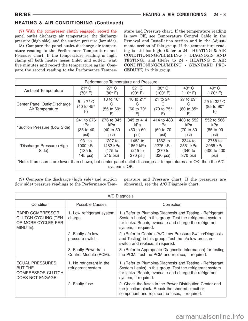
(7)With the compressor clutch engaged, record the
panel outlet discharge air temperature, the discharge
pressure (high side), and the suction pressure (low side).
(8) Compare the panel outlet discharge air temper-
ature reading to the Performance Temperature and
Pressure chart. If the temperature reading is high,
clamp off both heater hoses (inlet and outlet), wait
five minutes and record the temperature again. Com-
pare the second reading to the Performance Temper-ature and Pressure chart. If the temperature reading
is now OK, see Temperature Control Cable in the
Removal and Installation section and in the Adjust-
ments section of this group. If the temperature read-
ing is still too high, (Refer to 24 - HEATING & AIR
CONDITIONING/PLUMBING - DIAGNOSIS AND
TESTING), and (Refer to 24 - HEATING & AIR
CONDITIONING/PLUMBING - STANDARD PRO-
CEDURE) in this group.
Performance Temperature and Pressure
Ambient Temperature21É C
(70É F)27É C
(80É F)32É C
(90É F)38É C
(100É F)43É C
(110É F)49É C
(120É F)
Center Panel OutletDischarge
Air Temperature5to7ÉC
(40 to 45É
F)13 to 16É
C
(55 to 60É
F)16 to 21É
C
(60 to 70É
F)21 to 24É
C
(70 to 75É
F)27 to 29É
C
(80 to 85É
F)29 to 32É C
(85 to 90É
F)
*Suction Pressure (Low Side)241 to 276
kPa
(35 to 40
psi)276 to 345
kPa
(40 to 50
psi)345 to 414
kPa
(50 to 60
psi)414 to 483
kPa
(60 to 70
psi)483 to 552
kPa
(70 to 80
psi)552 to 586
kPa
(85 to 90
psi)
*Discharge Pressure (High
Side)931 to
1000 kPa
(135 to
145 psi)1207 to
1482 kPa
(175 to
215 psi)1482 to
1862 kPa
(215 to
270 psi)1862 to
2275 kPa
(270 to
330 psi)2344 to
2551 kPa
(340 to
370 psi)2758 to
2965 kPa
(400 to 430
psi)
*Note: If pressures are lower than shown, but center panel outlet discharge air temperatures are OK, then the A/C
system is OK.
(9) Compare the discharge (high side) and suction
(low side) pressure readings to the Performance Tem-perature and Pressure chart. If the pressures are
abnormal, see the A/C Diagnosis chart.
A/C Diagnosis
Condition Possible Causes Correction
RAPID COMPRESSOR
CLUTCH CYCLING (TEN
OR MORE CYCLES PER
MINUTE).1. Low refrigerant system
charge.1. (Refer to Plumbing/Diagnosis and Testing - Refrigerant
System Leaks) in this group. Test the refrigerant system
for leaks. Repair, evacuate and charge the refrigerant
system, if required.
2. Faulty a/c low
pressure switch.2. (Refer to Controls/A/C Low Pressure Switch/Diagnosis
and Testing) in this group. Test the a/c low pressure
switch and replace, if required.
3. Faulty Powertrain
Control Module (PCM).3. (Refer to Appropriate Diagnostic Information) for testing
the PCM. Test the PCM and replace, if required.
EQUAL PRESSURES,
BUT THE
COMPRESSOR CLUTCH
DOES NOT ENGAGE.1. No refrigerant in the
refrigerant system.1. (Refer to Plumbing/Diagnosis and Testing - Refrigerant
System Leaks) in this group. Test the refrigerant system
for leaks. Repair, evacuate and charge the refrigerant
system, if required.
2. Faulty fuse. 2. Check the fuses in the Power Distribution Center and
the junction block. Repair the shorted circuit or
component and replace the fuses, if required.
BR/BEHEATING & AIR CONDITIONING 24 - 3
HEATING & AIR CONDITIONING (Continued)
Page 2879 of 2889
SHIFT LEVER - INSTALLATION . . . 21-853,21-888,
21-924
SHIFT LEVER - INSTALLATION, GEAR.....19-13
SHIFT LEVER - REMOVAL . 21-852,21-887,21-924
SHIFT LEVER - REMOVAL, GEAR........19-13
SHIFT MECHANISM - ADJUSTMENT....21-252,
21-423,21-596,21-769
SHIFT MECHANISM - DESCRIPTION....21-251,
21-422,21-595,21-768
SHIFT MECHANISM - INSTALLATION.....21-89
SHIFT MECHANISM - OPERATION......21-251,
21-422,21-595,21-768
SHIFT MECHANISM - REMOVAL.........21-88
SHIFT/CLUTCH INTERLOCK SYSTEM -
INSPECTION........................30-19
SHIPPED LOOSE ITEMS - INSTALLATION . . 30-14
SHOCK - DESCRIPTION........2-11,2-21,2-28
SHOCK - DIAGNOSIS AND TESTING . . . 2-11,2-21
SHOCK - DIAGNOSIS AND TESTING,
SPRING.............................2-26
SHOCK - INSTALLATION........2-11,2-21,2-28
SHOCK - OPERATION..........2-11,2-21,2-28
SHOCK - REMOVAL............2-11,2-21,2-28
SHOES - 2500/3500 - INSTALLATION,
REAR DRUM IN HAT PARK BRAKE........5-42
SHOES - 2500/3500 - REMOVAL, REAR
DRUM IN HAT PARK BRAKE.............5-41
SHOES-11 INCH - INSTALLATION, REAR
BRAKE..............................5-27
SHOES-11 INCH - REMOVAL, REAR
BRAKE..............................5-25
SHORT TO GROUND - STANDARD
PROCEDURE, TESTING FOR A........8W-01-6
SHORT TO GROUND ON FUSES
POWERING SEVERAL LOADS -
STANDARD PROCEDURE, TESTING....8W-01-7
SHOULDER BELTS, RETRACTORS AND
HEAD RESTRAINTS - INSPECTION,
SEAT BELTS.........................30-12
SHUT DOWN RELAY - INSTALLATION,
AUTOMATIC..........................8I-5
SHUT DOWN RELAY - REMOVAL,
AUTOMATIC..........................8I-4
SHUTFACE HANDLE - INSTALLATION.....23-83
SHUTFACE HANDLE - REMOVAL.........23-83
SIDE MOLDINGS - INSTALLATION, BODY . . 23-87
SIDE MOLDINGS - REMOVAL, BODY.....23-87
SIDE PANEL SPEAKER - INSTALLATION,
REAR CAB..........................8A-21
SIDE PANEL SPEAKER - REMOVAL,
REAR CAB..........................8A-20
SIDE VIEW MIRROR - INSTALLATION.....23-97
SIDE VIEW MIRROR - LOW MOUNTED -
INSTALLATION.......................23-98
SIDE VIEW MIRROR - LOW MOUNTED -
REMOVAL..........................23-98
SIDE VIEW MIRROR - REMOVAL........23-97
SIDE VIEW MIRROR FLAG -
INSTALLATION.......................23-74
SIDE VIEW MIRROR FLAG - REMOVAL . . . 23-74
SIDE VIEW MIRROR GLASS -
INSTALLATION.......................23-98
SIDE VIEW MIRROR GLASS - REMOVAL . . 23-98
SIDEVIEW MIRROR - DESCRIPTION......8N-13
SIDEVIEW MIRROR - DIAGNOSIS AND
TESTING...........................8N-13
SIDEVIEW MIRROR - OPERATION.......8N-13
SIDEVIEW MIRROR - REMOVAL.........8N-14
SIGNAL & HAZARD WARNING SYSTEM -
DESCRIPTION, TURN..................8L-2
SIGNAL & HAZARD WARNING SYSTEM -
DIAGNOSIS AND TESTING, TURN.........8L-3
SIGNAL & HAZARD WARNING SYSTEM -
OPERATION, TURN....................8L-2
SIGNAL CANCEL CAM - DESCRIPTION,
TURN..............................8L-30
SIGNAL CANCEL CAM - OPERATION,
TURN..............................8L-31
SIGNAL GROUND - DESCRIPTION.......8E-17
SIGNAL INDICATORS - DESCRIPTION,
TURN
..............................8J-32
SIGNAL INDICATORS - DIAGNOSIS AND
TESTING, TURN
......................8J-32
SIGNAL INDICATORS - OPERATION,
TURN
..............................8J-32
SIGNAL LAMP - INSTALLATION,
PARK/TURN
.........................8L-29
SIGNAL LAMP - REMOVAL, PARK/TURN
. . 8L-29SIGNAL LAMP UNIT - INSTALLATION,
PARK/TURN.........................8L-29
SIGNAL LAMP UNIT - REMOVAL,
PARK/TURN.........................8L-29
SIGNALS - INSPECTION, TURN AND
EMERGENCY........................30-19
SILENCER PAD - INSTALLATION........23-103
SILENCER PAD - REMOVAL...........23-103
SILL TRIM - INSTALLATION, DOOR.....23-121
SILL TRIM - REMOVAL, DOOR.........23-121
SINGLE CARDAN UNIVERSAL JOINTS -
DISASSEMBLY........................3-11
SINGLE CARDAN UNIVERSAL JOINTS -
INSTALLATION....................3-34,3-66
SINGLE CARDAN UNIVERSAL JOINTS -
REMOVAL.......................3-33,3-65
SKID PLATE - INSTALLATION, TRANSFER
CASE..............................13-11
SKID PLATE - REMOVAL, TRANSFER
CASE..............................13-11
SLAM BUMPER - INSTALLATION........23-66
SLAM BUMPER - REMOVAL............23-66
SMOKE DIAGNOSIS CHARTS -
DIAGNOSIS AND TESTING.............9-234
SOLENOID - DESCRIPTION.....21-252,21-423,
21-596,21-769
SOLENOID - DESCRIPTION, EVAP/PURGE . 25-32
SOLENOID - INSTALLATION, EVAP/
PURGE.............................25-32
SOLENOID - OPERATION . 21-253,21-424,21-597,
21-770
SOLENOID - REMOVAL, EVAP/PURGE.....25-32
SOLID LIFTERS/TAPPETS - CLEANING....9-281
SOLID LIFTERS/TAPPETS - INSPECTION . . 9-281
SOLID LIFTERS/TAPPETS -
INSTALLATION.......................9-281
SOLID LIFTERS/TAPPETS - REMOVAL....9-280
SPARE TIRE - DESCRIPTION.............22-9
SPARE TIRE WINCH - INSTALLATION.....13-10
SPARE TIRE WINCH - REMOVAL........13-10
SPARK PLUG - CLEANING..............8I-19
SPARK PLUG - DESCRIPTION...........8I-16
SPARK PLUG - INSTALLATION...........8I-19
SPARK PLUG - OPERATION.............8I-16
SPARK PLUG - REMOVAL..............8I-18
SPARK PLUG CABLE - DESCRIPTION.....8I-19
SPARK PLUG CABLE - INSTALLATION.....8I-20
SPARK PLUG CABLE - OPERATION.......8I-19
SPARK PLUG CABLE - REMOVAL........8I-20
SPARK PLUG CABLE ORDER, 8.0L V-10
ENGINE..............................8I-2
SPARK PLUG CABLE RESISTANCE,
SPECIFICATIONS......................8I-3
SPARK PLUG CABLES - DIAGNOSIS AND
TESTING............................8I-19
SPARK PLUG CONDITIONS - DIAGNOSIS
AND TESTING........................8I-16
SPARK PLUGS, SPECIFICATIONS..........8I-3
SPEAKER - DESCRIPTION..............8A-17
SPEAKER - DIAGNOSIS AND TESTING....8A-18
SPEAKER - INSTALLATION, A-PILLAR
TWEETER..........................8A-19
SPEAKER - INSTALLATION, FRONT DOOR . 8A-20
SPEAKER - INSTALLATION, REAR CAB
SIDE PANEL........................8A-21
SPEAKER - INSTALLATION, REAR DOOR . . 8A-21
SPEAKER - OPERATION...............8A-17
SPEAKER - REMOVAL, A-PILLAR
TWEETER..........................8A-19
SPEAKER - REMOVAL, FRONT DOOR.....8A-20
SPEAKER - REMOVAL, REAR CAB SIDE
PANEL.............................8A-20
SPEAKER - REMOVAL, REAR DOOR......8A-21
SPECIAL TOOLS - 5.2L ENGINE..........9-77
SPECIAL TOOLS - 5.9L DIESEL ENGINE . . . 9-244
SPECIAL TOOLS - 5.9L ENGINE.........9-134
SPECIAL TOOLS - 8.0L ENGINE.........9-188
SPECIAL TOOLS - AUDIO SYSTEMS.......8A-4
SPECIAL TOOLS - BASE BRAKES..........5-4
SPECIAL TOOLS - COOLING.............7-18
SPECIAL TOOLS - DIESEL FUEL SYSTEM . . 14-59
SPECIAL TOOLS - FRONT AXLE
..........3-58
SPECIAL TOOLS - FRONT AXLES
.........3-25
SPECIAL TOOLS - FUEL SYSTEM
....14-36,14-4
SPECIAL TOOLS - HEADLAMP
ALIGNMENT
..........................8L-4
SPECIAL TOOLS - INDEPENDENT FRONT
SUSPENSION
..........................2-9SPECIAL TOOLS - LINK/COIL
SUSPENSION.........................2-16
SPECIAL TOOLS - NV5600 MANUAL
TRANSMISSION.....................21-127
SPECIAL TOOLS - OVERHEAD CONSOLE
SYSTEMS...........................8M-8
SPECIAL TOOLS - POWER
DISTRIBUTION SYSTEMS............8W-97-2
SPECIAL TOOLS - POWER STEERING
GEAR..............................19-20
SPECIAL TOOLS - POWER STEERING
PUMP.............................19-36
SPECIAL TOOLS - PROPELLER SHAFT......3-8
SPECIAL TOOLS - RE TRANSMISSION . . 21-534,
21-704
SPECIAL TOOLS - RE TRANSMISSIONS . 21-188,
21-359
SPECIAL TOOLS - STEERING LINKAGE . . . 19-39,
19-42
SPECIAL TOOLS - SUSPENSION-REAR.....2-28
SPECIAL TOOLS, AIRBAG SYSTEM.......8O-6
SPECIAL TOOLS, WIRING/TERMINAL . . . 8W-01-8
SPECIFICATIONS - 2001 BR PAINT
COLOR CODES.....................23-129
SPECIFICATIONS - 3.9L ENGINE..........9-14
SPECIFICATIONS - 5.2L ENGINE..........9-72
SPECIFICATIONS - 5.9L DIESEL.........9-242
SPECIFICATIONS - 5.9L ENGINE.........9-129
SPECIFICATIONS - 8.OL ENGINE.........9-184
SPECIFICATIONS - A/C APPLICATION
TABLE................................24-8
SPECIFICATIONS - ALIGNMENT...........2-6
SPECIFICATIONS - BASE BRAKE...........5-2
SPECIFICATIONS - BATTERY.............8F-6
SPECIFICATIONS - BODY GAP AND
FLUSH MEASUREMENTS...............23-56
SPECIFICATIONS - BODY OPENING
DIMENSIONS........................23-60
SPECIFICATIONS - BODY SEALER
LOCATIONS.........................23-47
SPECIFICATIONS - BRAKE FLUID.........5-15
SPECIFICATIONS - FLUID CAPACITIES......0-6
SPECIFICATIONS - FRAME DIMENSION....13-7
SPECIFICATIONS - FUEL INJECTION
PUMP DATA PLATE...................14-73
SPECIFICATIONS - GENERATOR RATINGS . . 8F-28
SPECIFICATIONS - IGNITION TIMING......8I-3
SPECIFICATIONS - POWER STEERING
GEAR..............................19-19
SPECIFICATIONS - PROPELLER SHAFT......3-8
SPECIFICATIONS - SPARK PLUG CABLE
RESISTANCE..........................8I-3
SPECIFICATIONS - SPARK PLUGS.........8I-3
SPECIFICATIONS - SPECIFICATIONS......24-46
SPECIFICATIONS - SPECIFICATIONS.....21-357
SPECIFICATIONS - STARTING SYSTEM....8F-38
SPECIFICATIONS - STRUCTURAL
ADHESIVE LOCATIONS................23-44
SPECIFICATIONS - TIRE REVOLUTIONS
PER MILE...........................22-9
SPECIFICATIONS - TORQUE.............7-17
SPECIFICATIONS - TORQUE . . . 9-133,9-18,9-187,
9-243,9-76
SPECIFICATIONS - TORQUE.............11-5
SPECIFICATIONS - TORQUE CHART........5-3
SPECIFICATIONS - TORQUE CHART . 19-19,19-39,
19-41,19-9
SPECIFICATIONS - TORQUE CHART . . . 2-15,2-27,
2-8
SPECIFICATIONS - TORQUE CHART......22-11
SPECIFICATIONS - TORQUE
SPECIFICATIONS.....................23-61
SPECIFICATIONS - TORQUE
SPECIFICATIONS......................13-9
SPECIFICATIONS - TORQUE
SPECIFICATIONS......................24-8
SPECIFICATIONS - TRANSFER CASE....21-848,
21-883,21-919
SPECIFICATIONS - TRANSMISSION.....21-186,
21-532,21-702
SPECIFICATIONS - WELD LOCATIONS.....23-4
SPECIFICATIONS, CLUTCH...............6-7
SPECIFICATIONS, FUEL SYSTEM
PRESSURE - GAS ENGINES
.............14-4
SPECIFICATIONS, NV4500
..............21-83
SPECIFICATIONS, NV5600
.............21-126
SPECIFICATIONS, SPECIFICATIONS
.......24-46
SPECIFICATIONS, SPECIFICATIONS
......21-357
32 INDEXBR/BE
Description Group-Page Description Group-Page Description Group-Page