2001 DODGE RAM oil capacities
[x] Cancel search: oil capacitiesPage 19 of 2889
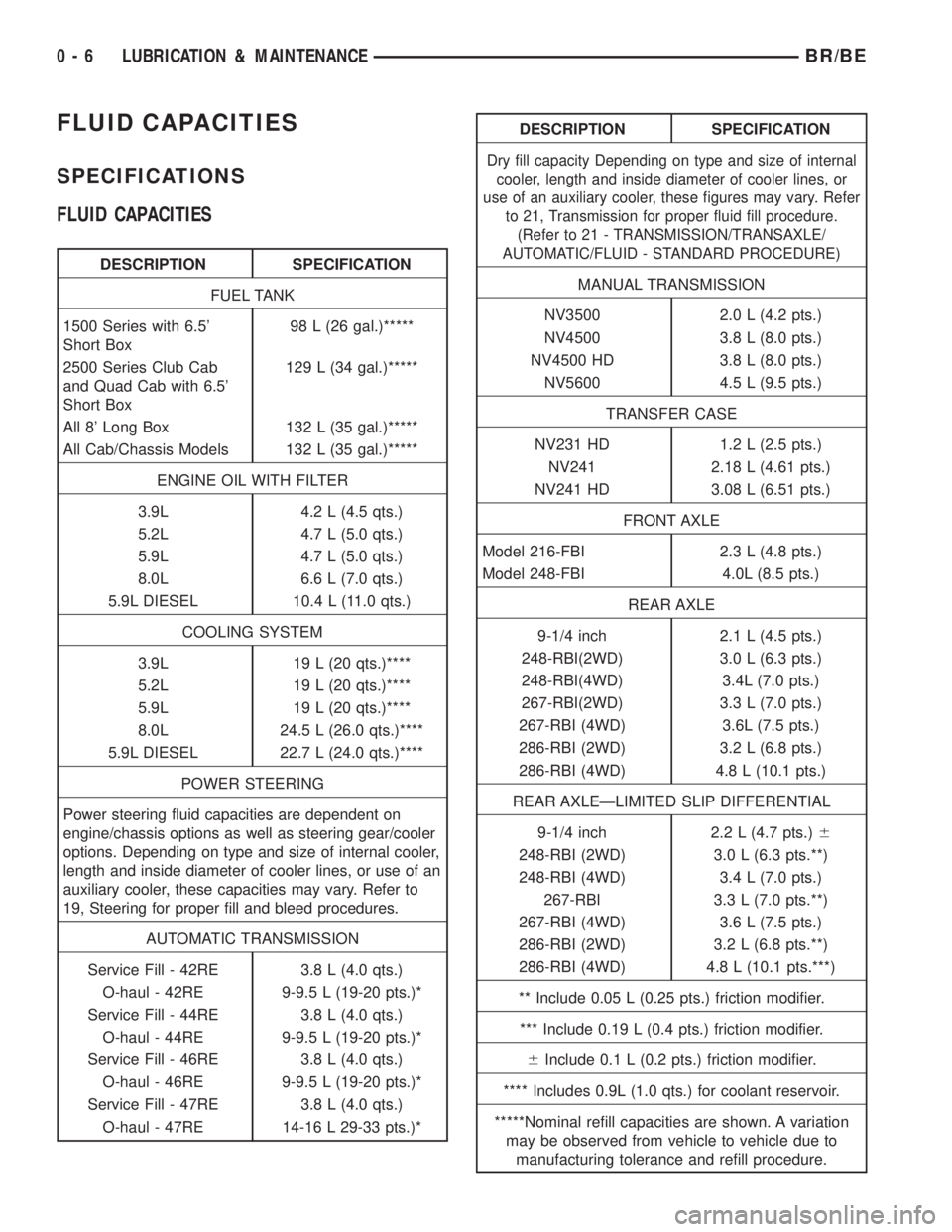
FLUID CAPACITIES
SPECIFICATIONS
FLUID CAPACITIES
DESCRIPTION SPECIFICATION
FUEL TANK
1500 Series with 6.5'
Short Box98 L (26 gal.)*****
2500 Series Club Cab
and Quad Cab with 6.5'
Short Box129 L (34 gal.)*****
All 8' Long Box 132 L (35 gal.)*****
All Cab/Chassis Models 132 L (35 gal.)*****
ENGINE OIL WITH FILTER
3.9L 4.2 L (4.5 qts.)
5.2L 4.7 L (5.0 qts.)
5.9L 4.7 L (5.0 qts.)
8.0L 6.6 L (7.0 qts.)
5.9L DIESEL 10.4 L (11.0 qts.)
COOLING SYSTEM
3.9L 19 L (20 qts.)****
5.2L 19 L (20 qts.)****
5.9L 19 L (20 qts.)****
8.0L 24.5 L (26.0 qts.)****
5.9L DIESEL 22.7 L (24.0 qts.)****
POWER STEERING
Power steering fluid capacities are dependent on
engine/chassis options as well as steering gear/cooler
options. Depending on type and size of internal cooler,
length and inside diameter of cooler lines, or use of an
auxiliary cooler, these capacities may vary. Refer to
19, Steering for proper fill and bleed procedures.
AUTOMATIC TRANSMISSION
Service Fill - 42RE 3.8 L (4.0 qts.)
O-haul - 42RE 9-9.5 L (19-20 pts.)*
Service Fill - 44RE 3.8 L (4.0 qts.)
O-haul - 44RE 9-9.5 L (19-20 pts.)*
Service Fill - 46RE 3.8 L (4.0 qts.)
O-haul - 46RE 9-9.5 L (19-20 pts.)*
Service Fill - 47RE 3.8 L (4.0 qts.)
O-haul - 47RE 14-16 L 29-33 pts.)*
DESCRIPTION SPECIFICATION
Dry fill capacity Depending on type and size of internal
cooler, length and inside diameter of cooler lines, or
use of an auxiliary cooler, these figures may vary. Refer
to 21, Transmission for proper fluid fill procedure.
(Refer to 21 - TRANSMISSION/TRANSAXLE/
AUTOMATIC/FLUID - STANDARD PROCEDURE)
MANUAL TRANSMISSION
NV3500 2.0 L (4.2 pts.)
NV4500 3.8 L (8.0 pts.)
NV4500 HD 3.8 L (8.0 pts.)
NV5600 4.5 L (9.5 pts.)
TRANSFER CASE
NV231 HD 1.2 L (2.5 pts.)
NV241 2.18 L (4.61 pts.)
NV241 HD 3.08 L (6.51 pts.)
FRONT AXLE
Model 216-FBI 2.3 L (4.8 pts.)
Model 248-FBI 4.0L (8.5 pts.)
REAR AXLE
9-1/4 inch 2.1 L (4.5 pts.)
248-RBI(2WD) 3.0 L (6.3 pts.)
248-RBI(4WD) 3.4L (7.0 pts.)
267-RBI(2WD) 3.3 L (7.0 pts.)
267-RBI (4WD) 3.6L (7.5 pts.)
286-RBI (2WD) 3.2 L (6.8 pts.)
286-RBI (4WD) 4.8 L (10.1 pts.)
REAR AXLEÐLIMITED SLIP DIFFERENTIAL
9-1/4 inch 2.2 L (4.7 pts.)6
248-RBI (2WD) 3.0 L (6.3 pts.**)
248-RBI (4WD) 3.4 L (7.0 pts.)
267-RBI 3.3 L (7.0 pts.**)
267-RBI (4WD) 3.6 L (7.5 pts.)
286-RBI (2WD) 3.2 L (6.8 pts.**)
286-RBI (4WD) 4.8 L (10.1 pts.***)
** Include 0.05 L (0.25 pts.) friction modifier.
*** Include 0.19 L (0.4 pts.) friction modifier.
6Include 0.1 L (0.2 pts.) friction modifier.
**** Includes 0.9L (1.0 qts.) for coolant reservoir.
*****Nominal refill capacities are shown. A variation
may be observed from vehicle to vehicle due to
manufacturing tolerance and refill procedure.
0 - 6 LUBRICATION & MAINTENANCEBR/BE
Page 513 of 2889
5.9L DIESEL ENGINE
(1) If equipped, position aluminum spacer to rear
of starter.
(2) Position starter motor to engine.
(3) Support starter and loosely install three
mounting bolts.
(4) Tighten 3 bolts to 43.4 N´m (32 ft. lbs.).
(5) Position wiring eyelets to starter studs and
install nuts. Tighten small nut to 6.2 N´m (55 in.
lbs.). Tighten large nut to 13.6 N´m (120 in. lbs.).
(6) Install protective rubber boot over stud.
(7) Lower vehicle.
(8) Connect battery cables to both batteries.
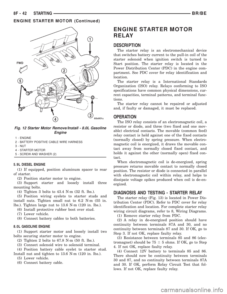
8.0L GASOLINE ENGINE
(1) Support starter motor and loosely install two
bolts securing starter motor to engine.
(2) Tighten 2 bolts to 67.8 N´m (50 ft. lbs.).
(3) Connect solenoid wire to solenoid terminal.
(4) Position battery cable eyelet to starter stud.
Install nut and tighten to 13.6 N´m (120 in. lbs.).
(5) Lower vehicle.
(6) Connect battery cable.
ENGINE STARTER MOTOR
RELAY
DESCRIPTION
The starter relay is an electromechanical device
that switches battery current to the pull-in coil of the
starter solenoid when ignition switch is turned to
Start position. The starter relay is located in the
Power Distribution Center (PDC) in the engine com-
partment. See PDC cover for relay identification and
location.
The starter relay is a International Standards
Organization (ISO) relay. Relays conforming to ISO
specifications have common physical dimensions, cur-
rent capacities, terminal patterns, and terminal func-
tions.
The starter relay cannot be repaired or adjusted
and, if faulty or damaged, it must be replaced.
OPERATION
The ISO relay consists of an electromagnetic coil, a
resistor or diode, and three (two fixed and one mov-
able) electrical contacts. The movable (common feed)
relay contact is held against one of the fixed contacts
(normally closed) by spring pressure. When electro-
magnetic coil is energized, it draws the movable con-
tact away from normally closed fixed contact, and
holds it against the other (normally open) fixed con-
tact.
When electromagnetic coil is de-energized, spring
pressure returns movable contact to normally closed
position. The resistor or diode is connected in parallel
with electromagnetic coil within relay, and helps to
dissipate voltage spikes produced when coil is de-en-
ergized.
DIAGNOSIS AND TESTING - STARTER RELAY
The starter relay (Fig. 13) is located in Power Dis-
tribution Center (PDC). Refer to PDC cover for relay
identification and location. For complete starter relay
wiring circuit diagrams, refer to 8, Wiring Diagrams.
(1) Remove starter relay from PDC.
(2) A relay in de-energized position should have
continuity between terminals 87A and 30, and no
continuity between terminals 87 and 30. If OK, go to
Step 3. If not OK, replace faulty relay.
(3) Resistance between terminals 85 and 86 (elec-
tromagnet) should be 7565 ohms. If OK, go to Step
4. If not OK, replace faulty relay.
(4) Connect 12V battery to terminals 85 and 86.
There should now be continuity between terminals
30 and 87, and no continuity between terminals 87A
and 30. If OK, perform Relay Circuit Test that fol-
lows. If not OK, replace faulty relay.
Fig. 12 Starter Motor Remove/Install - 8.0L Gasoline
Engine
1 - ENGINE
2 - BATTERY POSITIVE CABLE WIRE HARNESS
3 - NUT
4 - STARTER MOTOR
5 - SCREW AND WASHER (2)
8F - 42 STARTINGBR/BE
ENGINE STARTER MOTOR (Continued)
Page 527 of 2889
ifications have common physical dimensions, current
capacities, terminal patterns, and terminal functions.
The ISO micro-relay terminal functions are the same
as a conventional ISO relay. However, the ISO micro-
relay terminal pattern (or footprint) is different, the
current capacity is lower, and the physical dimen-
sions are smaller than those of the conventional ISO
relay.
The heated seat relay cannot be repaired or
adjusted and, if faulty or damaged, it must be
replaced.
OPERATION
The ISO relay consists of an electromagnetic coil, a
resistor or diode, and three (two fixed and one mov-
able) electrical contacts. The movable (common feed)
relay contact is held against one of the fixed contacts
(normally closed) by spring pressure. When the elec-
tromagnetic coil is energized, it draws the movable
contact away from the normally closed fixed contact,
and holds it against the other (normally open) fixed
contact. When the electromagnetic coil is de-ener-
gized, spring pressure returns the movable contact to
the normally closed position. The resistor or diode is
connected in parallel with the electromagnetic coil in
the relay, and helps to dissipate voltage spikes that
are produced when the coil is de-energized.
The heated seat relay is controlled by the premium
version of the Central Timer Module (CTM), which
controls the ground feed to the coil ground terminal
of the relay to energize and de-energize the electro-
magnetic coil of the relay. The CTM monitors engine
operation through messages it receives from the Pow-
ertrain Control Module (PCM) over the Chrysler Col-
lision Detection (CCD) data bus network. The CTM is
programmed to energize the relay only when the
engine is running, and to de-energize the relay when
the engine is not running. Refer toCentral Timer
Modulein the index of this service manual for the
location of more information on the premium CTM.
DIAGNOSIS & TESTING - HEATED SEAT RELAY
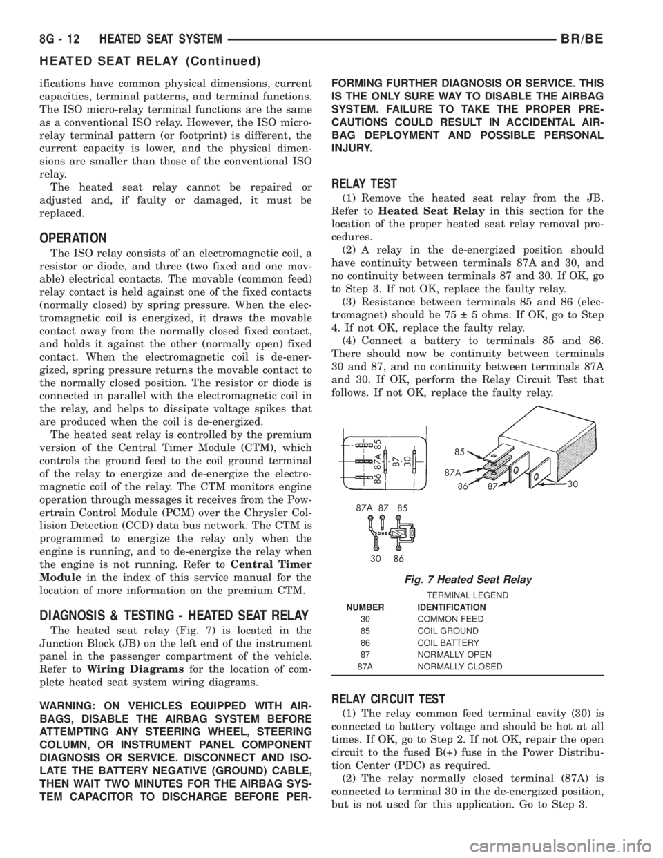
The heated seat relay (Fig. 7) is located in the
Junction Block (JB) on the left end of the instrument
panel in the passenger compartment of the vehicle.
Refer toWiring Diagramsfor the location of com-
plete heated seat system wiring diagrams.
WARNING: ON VEHICLES EQUIPPED WITH AIR-
BAGS, DISABLE THE AIRBAG SYSTEM BEFORE
ATTEMPTING ANY STEERING WHEEL, STEERING
COLUMN, OR INSTRUMENT PANEL COMPONENT
DIAGNOSIS OR SERVICE. DISCONNECT AND ISO-
LATE THE BATTERY NEGATIVE (GROUND) CABLE,
THEN WAIT TWO MINUTES FOR THE AIRBAG SYS-
TEM CAPACITOR TO DISCHARGE BEFORE PER-FORMING FURTHER DIAGNOSIS OR SERVICE. THIS
IS THE ONLY SURE WAY TO DISABLE THE AIRBAG
SYSTEM. FAILURE TO TAKE THE PROPER PRE-
CAUTIONS COULD RESULT IN ACCIDENTAL AIR-
BAG DEPLOYMENT AND POSSIBLE PERSONAL
INJURY.
RELAY TEST
(1) Remove the heated seat relay from the JB.
Refer toHeated Seat Relayin this section for the
location of the proper heated seat relay removal pro-
cedures.
(2) A relay in the de-energized position should
have continuity between terminals 87A and 30, and
no continuity between terminals 87 and 30. If OK, go
to Step 3. If not OK, replace the faulty relay.
(3) Resistance between terminals 85 and 86 (elec-
tromagnet) should be 75 5 ohms. If OK, go to Step
4. If not OK, replace the faulty relay.
(4) Connect a battery to terminals 85 and 86.
There should now be continuity between terminals
30 and 87, and no continuity between terminals 87A
and 30. If OK, perform the Relay Circuit Test that
follows. If not OK, replace the faulty relay.
RELAY CIRCUIT TEST
(1) The relay common feed terminal cavity (30) is
connected to battery voltage and should be hot at all
times. If OK, go to Step 2. If not OK, repair the open
circuit to the fused B(+) fuse in the Power Distribu-
tion Center (PDC) as required.
(2) The relay normally closed terminal (87A) is
connected to terminal 30 in the de-energized position,
but is not used for this application. Go to Step 3.
Fig. 7 Heated Seat Relay
TERMINAL LEGEND
NUMBER IDENTIFICATION
30 COMMON FEED
85 COIL GROUND
86 COIL BATTERY
87 NORMALLY OPEN
87A NORMALLY CLOSED
8G - 12 HEATED SEAT SYSTEMBR/BE
HEATED SEAT RELAY (Continued)
Page 534 of 2889
INSTALLATION
(1) Position the horn and mounting bracket unit(s)
onto the right fender wheel house front extension.
(2) Install and tighten the screw that secures the
horn and mounting bracket unit(s) to the right
fender wheel house front extension. Tighten the
screw to 11 N´m (95 in. lbs.).
(3) Reconnect the wire harness connector(s) to the
horn connector receptacle(s).
(4) Reconnect the battery negative cable.
HORN RELAY
DESCRIPTION
The horn relay is a electromechanical device that
switches battery current to the horn when the horn
switch grounds the relay coil. The horn relay is
located in the Power Distribution Center (PDC) in
the engine compartment. If a problem is encountered
with a continuously sounding horn, it can usually be
quickly resolved by removing the horn relay from the
PDC until further diagnosis is completed. See the
fuse and relay layout label affixed to the inside sur-
face of the PDC cover for horn relay identification
and location.
The horn relay is a International Standards Orga-
nization (ISO) micro-relay. Relays conforming to the
ISO specifications have common physical dimensions,
current capacities, terminal patterns, and terminal
functions. The ISO micro-relay terminal functions
are the same as a conventional ISO relay. However,
the ISO micro-relay terminal pattern (or footprint) is
different, the current capacity is lower, and the phys-
ical dimensions are smaller than those of the conven-
tional ISO relay.
The horn relay cannot be repaired or adjusted and,
if faulty or damaged, it must be replaced.
OPERATION
The ISO relay consists of an electromagnetic coil, a
resistor or diode, and three (two fixed and one mov-
able) electrical contacts. The movable (common feed)
relay contact is held against one of the fixed contacts
(normally closed) by spring pressure. When the elec-
tromagnetic coil is energized, it draws the movable
contact away from the normally closed fixed contact,
and holds it against the other (normally open) fixed
contact.
When the electromagnetic coil is de-energized,
spring pressure returns the movable contact to the
normally closed position. The resistor or diode is con-
nected in parallel with the electromagnetic coil in the
relay, and helps to dissipate voltage spikes that are
produced when the coil is de-energized.
DIAGNOSIS AND TESTING
DIAGNOSIS AND TESTING - HORN RELAY
The horn relay (Fig. 2) is located in the Power Dis-
tribution Center (PDC) behind the battery on the
driver side of the engine compartment. If a problem
is encountered with a continuously sounding horn, it
can usually be quickly resolved by removing the horn
relay from the PDC until further diagnosis is com-
pleted. See the fuse and relay layout label affixed to
the inside surface of the PDC cover for horn relay
identification and location. For complete circuit dia-
grams, refer to the appropriate wiring information.
The wiring information includes wiring diagrams,
proper wire and connector repair procedures, details
of wire harness routing and retention, connector pin-
out information and location views for the various
wire harness connectors, splices and grounds.
WARNING: ON VEHICLES EQUIPPED WITH AIR-
BAGS, REFER TO ELECTRICAL, RESTRAINTS
BEFORE ATTEMPTING ANY STEERING WHEEL,
STEERING COLUMN, OR INSTRUMENT PANEL
COMPONENT DIAGNOSIS OR SERVICE. FAILURE
TO TAKE THE PROPER PRECAUTIONS COULD
RESULT IN ACCIDENTAL AIRBAG DEPLOYMENT
AND POSSIBLE PERSONAL INJURY.
(1) Remove the horn relay from the PDC. (Refer to
8 - ELECTRICAL/HORN/HORN RELAY -
REMOVAL) for the procedures.
(2) A relay in the de-energized position should
have continuity between terminals 87A and 30, and
no continuity between terminals 87 and 30. If OK, go
to Step 3. If not OK, replace the faulty relay.
(3) Resistance between terminals 85 and 86 (elec-
tromagnet) should be 7565 ohms. If OK, go to Step
4. If not OK, replace the faulty relay.
(4) Connect a battery to terminals 85 and 86.
There should now be continuity between terminals
30 and 87, and no continuity between terminals 87A
and 30. If OK, perform the Relay Circuit Test that
follows. If not OK, replace the faulty relay.
RELAY CIRCUIT TEST
(1) The relay common feed terminal cavity (30) is
connected to battery voltage and should be hot at all
times. If OK, go to Step 2. If not OK, repair the open
circuit to the fuse in the PDC as required.
(2) The relay normally closed terminal (87A) is
connected to terminal 30 in the de-energized position,
but is not used for this application. Go to Step 3.
BR/BEHORN 8H - 3
HORN (Continued)
Page 613 of 2889
CONDITION POSSIBLE CAUSES CORRECTION
HEADLAMP SWITCH ON
(HIGH BEAMS ON), ONE
HIGH BEAM ON AND
BOTH LOW BEAMS DIM.1. Headlamp feed circuit shorted to
ground.1. Check wiring circuit from right headlamp
fuse to headlamp. Repeat for left side.
Trace short circuit in wiring and repair.
HEADLAMP SWITCH ON,
ONE HEADLAMP
FILAMENT WILL BE AT
FULL INTENSITY AND ALL
OTHER FILAMENTS ARE
ON AND DIM.1. Blown headlamp fuse. 1. Trace short circuit and replace fuse.
2. Open circuit from headlamp fuse
to headlamp.2. Repair open headlamp circuit.
1. HEADLAMPS STAY ON
WITH KEY OUT (DRLM
EQUIPPED VEHICLES).1. Failed DRLM 1. Replace DRLM.
*Canada vehicles must have lamps ON.
REMOVAL
On the driver side, the battery and battery tray
must be removed to service the headlamp bulb.
(1) Disconnect and isolate the battery negative
cable.
(2) Remove the battery tray (Refer to 8 - ELEC-
TRICAL/BATTERY SYSTEM/TRAY - REMOVAL).
(3) Disengage wire connector from headlamp
bulb(s).
(4) Remove retaining ring holding bulb(s) to head-
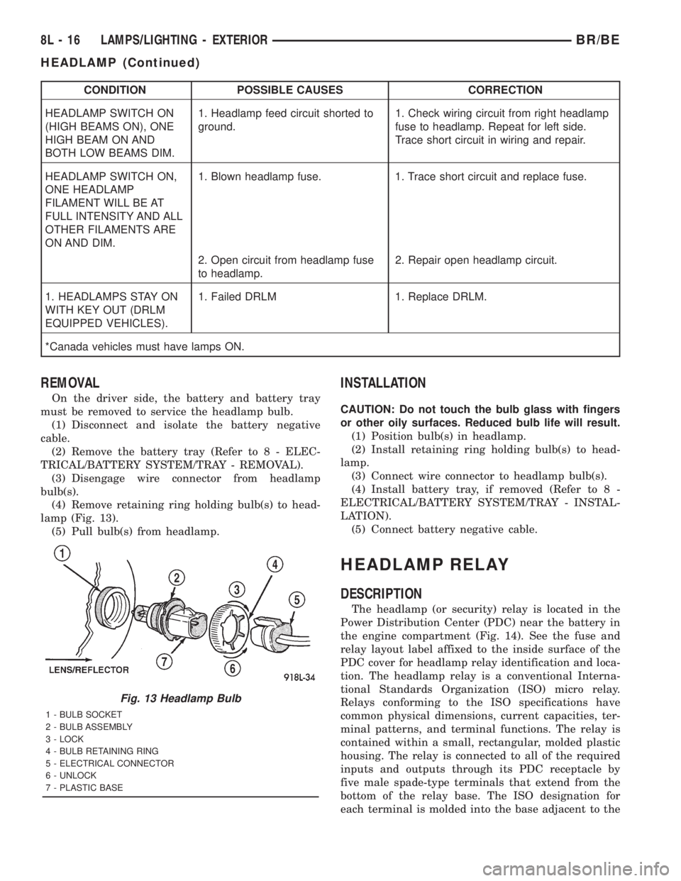
lamp (Fig. 13).
(5) Pull bulb(s) from headlamp.
INSTALLATION
CAUTION: Do not touch the bulb glass with fingers
or other oily surfaces. Reduced bulb life will result.
(1) Position bulb(s) in headlamp.
(2) Install retaining ring holding bulb(s) to head-
lamp.
(3) Connect wire connector to headlamp bulb(s).
(4) Install battery tray, if removed (Refer to 8 -
ELECTRICAL/BATTERY SYSTEM/TRAY - INSTAL-
LATION).
(5) Connect battery negative cable.
HEADLAMP RELAY
DESCRIPTION
The headlamp (or security) relay is located in the
Power Distribution Center (PDC) near the battery in
the engine compartment (Fig. 14). See the fuse and
relay layout label affixed to the inside surface of the
PDC cover for headlamp relay identification and loca-
tion. The headlamp relay is a conventional Interna-
tional Standards Organization (ISO) micro relay.
Relays conforming to the ISO specifications have
common physical dimensions, current capacities, ter-
minal patterns, and terminal functions. The relay is
contained within a small, rectangular, molded plastic
housing. The relay is connected to all of the required
inputs and outputs through its PDC receptacle by
five male spade-type terminals that extend from the
bottom of the relay base. The ISO designation for
each terminal is molded into the base adjacent to the
Fig. 13 Headlamp Bulb
1 - BULB SOCKET
2 - BULB ASSEMBLY
3 - LOCK
4 - BULB RETAINING RING
5 - ELECTRICAL CONNECTOR
6 - UNLOCK
7 - PLASTIC BASE
8L - 16 LAMPS/LIGHTING - EXTERIORBR/BE
HEADLAMP (Continued)
Page 738 of 2889
(6) Disconnect the headlamp and dash wire har-
ness connector for the wiper motor from the wiper
motor pigtail wire connector.
(7) Disconnect the headlamp and dash wire har-
ness ground connector from the wiper motor ground
terminal.
(8) Remove the wiper module from the cowl ple-
num as a unit.
INSTALLATION
(1) Position the wiper module into the cowl ple-
num as a unit.
(2) Reconnect the headlamp and dash wire harness
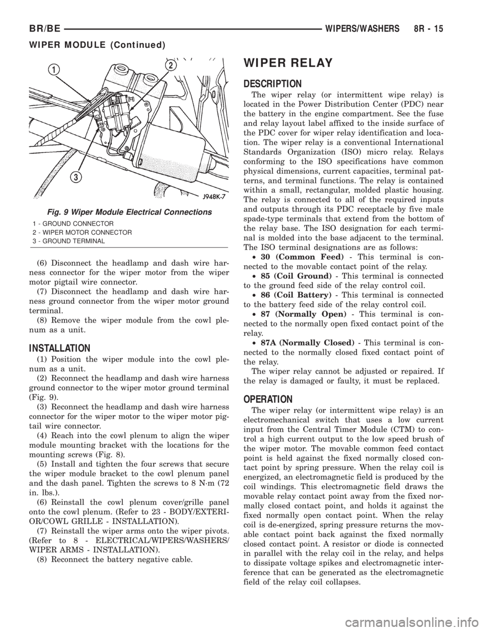
ground connector to the wiper motor ground terminal
(Fig. 9).
(3) Reconnect the headlamp and dash wire harness
connector for the wiper motor to the wiper motor pig-
tail wire connector.
(4) Reach into the cowl plenum to align the wiper
module mounting bracket with the locations for the
mounting screws (Fig. 8).
(5) Install and tighten the four screws that secure
the wiper module bracket to the cowl plenum panel
and the dash panel. Tighten the screws to 8 N´m (72
in. lbs.).
(6) Reinstall the cowl plenum cover/grille panel
onto the cowl plenum. (Refer to 23 - BODY/EXTERI-
OR/COWL GRILLE - INSTALLATION).
(7) Reinstall the wiper arms onto the wiper pivots.
(Refer to 8 - ELECTRICAL/WIPERS/WASHERS/
WIPER ARMS - INSTALLATION).
(8) Reconnect the battery negative cable.
WIPER RELAY
DESCRIPTION
The wiper relay (or intermittent wipe relay) is
located in the Power Distribution Center (PDC) near
the battery in the engine compartment. See the fuse
and relay layout label affixed to the inside surface of
the PDC cover for wiper relay identification and loca-
tion. The wiper relay is a conventional International
Standards Organization (ISO) micro relay. Relays
conforming to the ISO specifications have common
physical dimensions, current capacities, terminal pat-
terns, and terminal functions. The relay is contained
within a small, rectangular, molded plastic housing.
The relay is connected to all of the required inputs
and outputs through its PDC receptacle by five male
spade-type terminals that extend from the bottom of
the relay base. The ISO designation for each termi-
nal is molded into the base adjacent to the terminal.
The ISO terminal designations are as follows:
²30 (Common Feed)- This terminal is con-
nected to the movable contact point of the relay.
²85 (Coil Ground)- This terminal is connected
to the ground feed side of the relay control coil.
²86 (Coil Battery)- This terminal is connected
to the battery feed side of the relay control coil.
²87 (Normally Open)- This terminal is con-
nected to the normally open fixed contact point of the
relay.
²87A (Normally Closed)- This terminal is con-
nected to the normally closed fixed contact point of
the relay.
The wiper relay cannot be adjusted or repaired. If
the relay is damaged or faulty, it must be replaced.
OPERATION
The wiper relay (or intermittent wipe relay) is an
electromechanical switch that uses a low current
input from the Central Timer Module (CTM) to con-
trol a high current output to the low speed brush of
the wiper motor. The movable common feed contact
point is held against the fixed normally closed con-
tact point by spring pressure. When the relay coil is
energized, an electromagnetic field is produced by the
coil windings. This electromagnetic field draws the
movable relay contact point away from the fixed nor-
mally closed contact point, and holds it against the
fixed normally open contact point. When the relay
coil is de-energized, spring pressure returns the mov-
able contact point back against the fixed normally
closed contact point. A resistor or diode is connected
in parallel with the relay coil in the relay, and helps
to dissipate voltage spikes and electromagnetic inter-
ference that can be generated as the electromagnetic
field of the relay coil collapses.
Fig. 9 Wiper Module Electrical Connections
1 - GROUND CONNECTOR
2 - WIPER MOTOR CONNECTOR
3 - GROUND TERMINAL
BR/BEWIPERS/WASHERS 8R - 15
WIPER MODULE (Continued)
Page 1443 of 2889
²Milky discoloration indicates coolant dilution.
(4) Clean the area around the oil filter head.
Remove the filter (Refer to 9 - ENGINE/LUBRICA-
TION/OIL FILTER - REMOVAL).
(5) Install new oil filter (Refer to 9 - ENGINE/LU-
BRICATION/OIL FILTER - INSTALLATION).
(6) Clean the drain plug and the sealing surface of
the pan. Check the condition of the threads and seal-
ing surface on the oil pan and drain plug.
(7) Install the drain plug. Tighten the plug to 60
N´m (44 ft. lbs.) torque.
(8) Use only High-Quality Multi-Viscosity lubricat-
ing oil in the Cummins Turbo Diesel engine. Choose
the correct oil for the operating conditions (Refer to
LUBRICATION & MAINTENANCE/FLUID TYPES -
DESCRIPTION).
(9) Fill the engine with the correct grade of new oil
(Refer to LUBRICATION & MAINTENANCE/FLUID
CAPACITIES - SPECIFICATIONS).
(10) Start the engine and operate it at idle for sev-
eral minutes. Check for leaks at the filter and drain
plug.
(11) Stop engine. Wait several minutes to allow the
oil to drain back to the pan and check the level
again.
USED ENGINE OIL DISPOSAL Care should be
exercised when disposing of used engine oil after
it has been drained from a vehicle's engine.
OIL COOLER & LINES
CLEANING AND INSPECTION
Clean the sealing surfaces.
Apply 483 kPa (70 psi) air pressure to the element
to check for leaks. If the element leaks, replace the
element.
OIL FILTER
REMOVAL
(1) Clean the area around the oil filter head.
Remove the filter using a 90-95 mm filter wrench.
(2) Clean the gasket surface of the filter head. The
filter canister O-Ring seal can stick on the filter
head. Make sure it is removed.
INSTALLATION
(1) Fill the oil filter element with clean oil before
installation. Use the same type oil that will be used
in the engine.
(2) Apply a light film of lubricating oil to the seal-
ing surface before installing the filter.CAUTION: Mechanical over-tightening may distort
the threads or damage the filter element seal.
(3) Install the filter until it contacts the sealing
surface of the oil filter adapter. Tighten filter an
additional ó turn.
OIL PAN
REMOVAL
(1) Disconnect the battery negative cables.
(2) Raise vehicle on hoist.
(3) Remove transmission and transfer case (if
equipped).
(4) Remove flywheel.
(5) Disconnect starter cables from starter motor.
(6) Remove starter motor (Refer to 8 - ELECTRI-
CAL/STARTING/STARTER MOTOR - REMOVAL)
and transmission adapter plate assembly.
WARNING: HOT OIL CAN CAUSE PERSONAL
INJURY.
(7) Drain the engine oil (Refer to 9 - ENGINE/LU-
BRICATION/OIL - STANDARD PROCEDURE).
(8) Install the oil pan drain plug with a new seal-
ing washer and tighten to 60 N´m (44 ft. lbs.) torque.
(9) Remove oil pan bolts, break the pan to block
seal, and lower pan slightly and remove oil suction
tube fasteners.
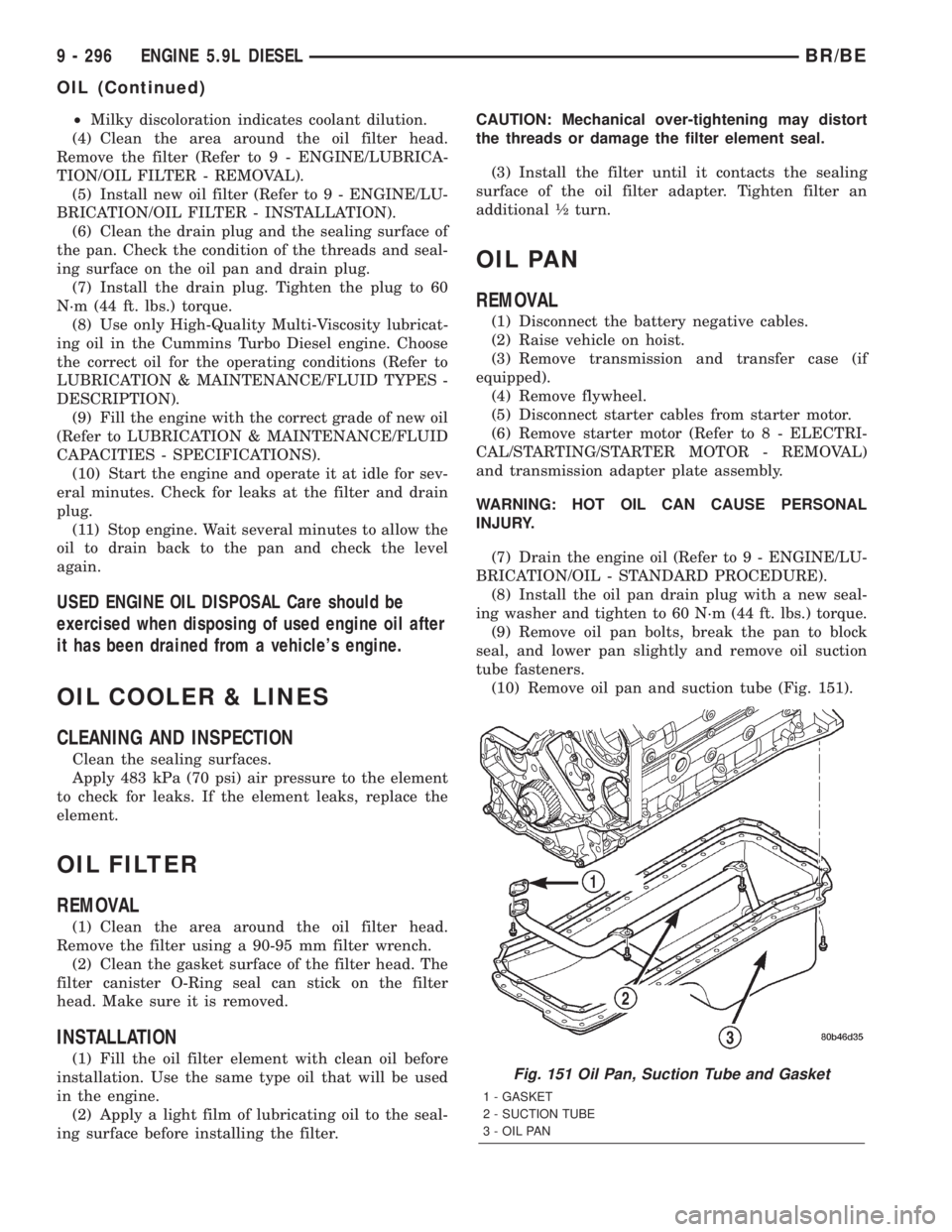
(10) Remove oil pan and suction tube (Fig. 151).
Fig. 151 Oil Pan, Suction Tube and Gasket
1 - GASKET
2 - SUCTION TUBE
3 - OIL PAN
9 - 296 ENGINE 5.9L DIESELBR/BE
OIL (Continued)
Page 2786 of 2889
container immediately to prevent moisture contami-
nation.
STANDARD PROCEDURE - REFRIGERANT OIL
LEVEL
When an air conditioning system is assembled at
the factory, all components except the compressor are
refrigerant oil free. After the refrigerant system has
been charged and operated, the refrigerant oil in the
compressor is dispersed throughout the refrigerant
system. The accumulator, evaporator, condenser, and
compressor will each retain a significant amount of
the needed refrigerant oil.
It is important to have the correct amount of oil in
the refrigerant system. This ensures proper lubrica-
tion of the compressor. Too little oil will result in
damage to the compressor. Too much oil will reduce
the cooling capacity of the air conditioning system.
It will not be necessary to check the oil level in the
compressor or to add oil, unless there has been an oil
loss. An oil loss may occur due to a rupture or leak
from a refrigerant line, a connector fitting, a compo-
nent, or a component seal. If a leak occurs, add 30
milliliters (1 fluid ounce) of refrigerant oil to the
refrigerant system after the repair has been made.Refrigerant oil loss will be evident at the leak point
by the presence of a wet, shiny surface around the
leak.
Refrigerant oil must be added when a accumulator,
evaporator coil, or condenser are replaced. See the
Refrigerant Oil Capacities chart. When a compressor
is replaced, the refrigerant oil must be drained from
the old compressor and measured. Drain all of the
refrigerant oil from the new compressor, then fill the
new compressor with the same amount of refrigerant
oil that was drained out of the old compressor.
Refrigerant Oil Capacities
Component ml fl oz
A/C System 210 6.2
Accumulator 60 2
Condenser 30 1
Evaporator 60 2
Compressordrain and measure
the oil from the old
compressor - see
text.
BR/BEPLUMBING 24 - 57
REFRIGERANT OIL (Continued)