2001 DODGE RAM ground clearance
[x] Cancel search: ground clearancePage 43 of 2889
²Do not tow a vehicle in a manner that could
jeopardize the safety of the operator, pedestrians or
other motorists.
²Do not attach tow chains, T-hooks, J-hooks, or a
tow sling to a bumper, steering linkage, drive shafts
or a non-reinforced frame hole.
²Do not tow a heavily loaded vehicle. Damage to
the cab, cargo box or frame may result. Use a flatbed
device to transport a loaded vehicle.
GROUND CLEARANCE
CAUTION: If vehicle is towed with wheels removed,
install lug nuts to retain brake drums or rotors.
A towed vehicle should be raised until lifted wheels
are a minimum 100 mm (4 in) from the ground. Be
sure there is adequate ground clearance at the oppo-
site end of the vehicle, especially when towing over
rough terrain or steep rises in the road. If necessary,
remove the wheels from the lifted end of the vehicle
and lower the vehicle closer to the ground, to
increase the ground clearance at the opposite end of
the vehicle. Install lug nuts on wheel attaching studs
to retain brake drums or rotors.
RAMP ANGLE
If a vehicle with flat-bed towing equipment is used,
the approach ramp angle should not exceed 15
degrees.
TOWING WHEN KEYS ARE NOT AVAILABLE
When the vehicle is locked and keys are not avail-
able, use a flat bed hauler. A Wheel-lift or Sling-type
device can be used on 4WD vehicles providedall the
wheels are lifted off the ground using tow dol-
lies.
FOUR-WHEEL-DRIVE VEHICLE TOWING
Chrysler Corporation recommends that a vehicle be
transported on a flat-bed device. A Wheel-lift or
Sling-type device can be used providedall the
wheels are lifted off the ground using tow dol-
lies.
WARNING: WHEN TOWING A DISABLED VEHICLE
AND THE DRIVE WHEELS ARE SECURED IN A
WHEEL LIFT OR TOW DOLLIES, ENSURE THE
TRANSMISSION IS IN THE PARK POSITION (AUTO-
MATIC TRANSMISSION) OR A FORWARD DRIVE
GEAR (MANUAL TRANSMISSION).
CAUTION: Many vehicles are equipped with air
dams, spoilers, and/or ground effect panels. To
avoid component damage, a wheel-lift towing vehi-
cle or a flat-bed hauling vehicle is recommended.
0 - 30 LUBRICATION & MAINTENANCEBR/BE
TOWING (Continued)
Page 83 of 2889
(5) Position universal joint into pinion yoke for
Dana axles and tighten strap bolts to 29 N´m (22 ft.
lbs.).
(6) Position companion yoke onto the companion
flange for Corporate axles and tighten the bolts to
108 N´m (80 ft. lbs.).
(7) Lower the vehicle.
CENTER BEARING
DESCRIPTION
The two±piece propeller shaft uses a center bearing
to support the shafts. Two types of center bearings
are used. Type 1 is used with the 9 1/4 axle. Type 2
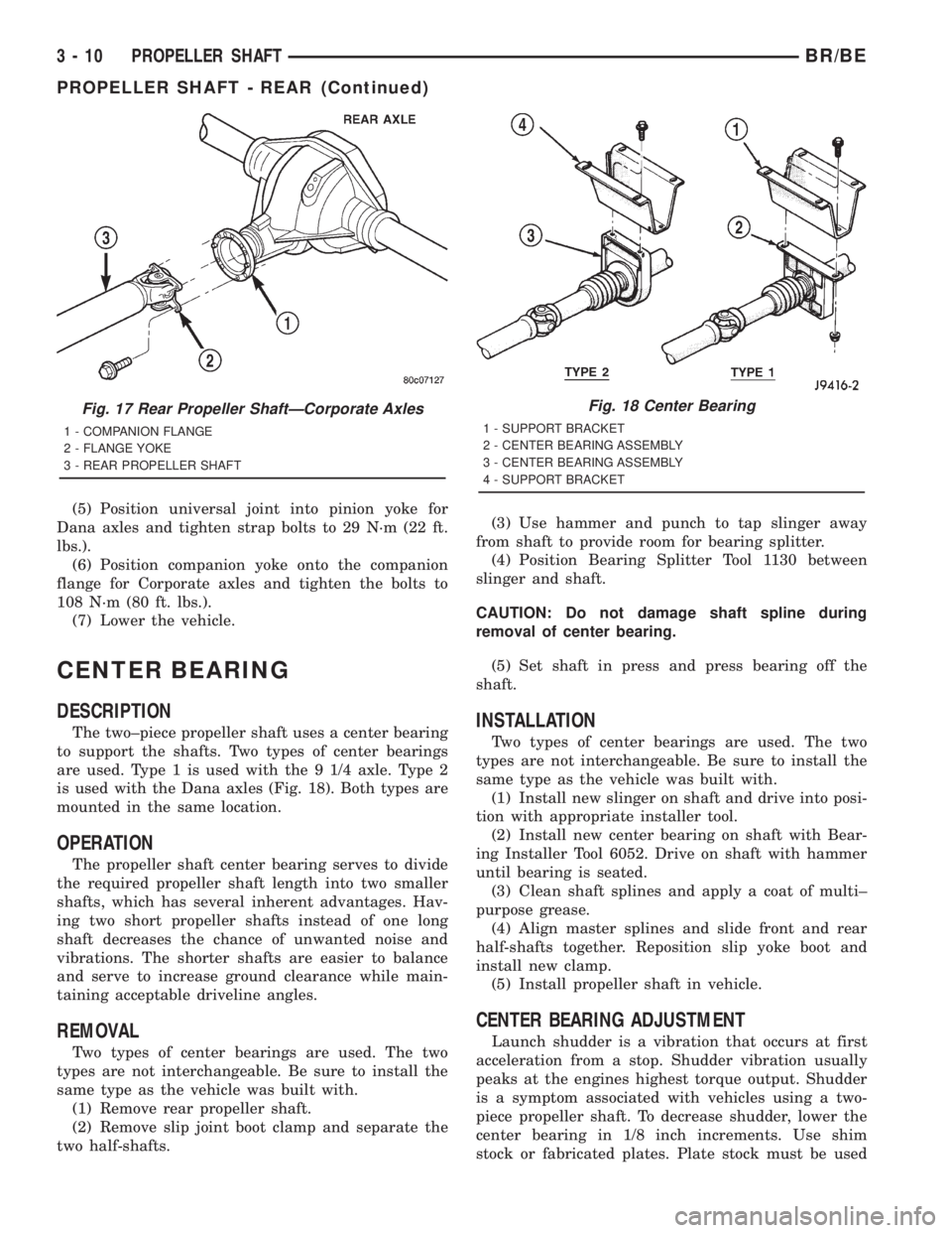
is used with the Dana axles (Fig. 18). Both types are
mounted in the same location.
OPERATION
The propeller shaft center bearing serves to divide
the required propeller shaft length into two smaller
shafts, which has several inherent advantages. Hav-
ing two short propeller shafts instead of one long
shaft decreases the chance of unwanted noise and
vibrations. The shorter shafts are easier to balance
and serve to increase ground clearance while main-
taining acceptable driveline angles.
REMOVAL
Two types of center bearings are used. The two
types are not interchangeable. Be sure to install the
same type as the vehicle was built with.
(1) Remove rear propeller shaft.
(2) Remove slip joint boot clamp and separate the
two half-shafts.(3) Use hammer and punch to tap slinger away
from shaft to provide room for bearing splitter.
(4) Position Bearing Splitter Tool 1130 between
slinger and shaft.
CAUTION: Do not damage shaft spline during
removal of center bearing.
(5) Set shaft in press and press bearing off the
shaft.
INSTALLATION
Two types of center bearings are used. The two
types are not interchangeable. Be sure to install the
same type as the vehicle was built with.
(1) Install new slinger on shaft and drive into posi-
tion with appropriate installer tool.
(2) Install new center bearing on shaft with Bear-
ing Installer Tool 6052. Drive on shaft with hammer
until bearing is seated.
(3) Clean shaft splines and apply a coat of multi±
purpose grease.
(4) Align master splines and slide front and rear
half-shafts together. Reposition slip yoke boot and
install new clamp.
(5) Install propeller shaft in vehicle.
CENTER BEARING ADJUSTMENT
Launch shudder is a vibration that occurs at first
acceleration from a stop. Shudder vibration usually
peaks at the engines highest torque output. Shudder
is a symptom associated with vehicles using a two-
piece propeller shaft. To decrease shudder, lower the
center bearing in 1/8 inch increments. Use shim
stock or fabricated plates. Plate stock must be used
Fig. 17 Rear Propeller ShaftÐCorporate Axles
1 - COMPANION FLANGE
2 - FLANGE YOKE
3 - REAR PROPELLER SHAFT
Fig. 18 Center Bearing
1 - SUPPORT BRACKET
2 - CENTER BEARING ASSEMBLY
3 - CENTER BEARING ASSEMBLY
4 - SUPPORT BRACKET
3 - 10 PROPELLER SHAFTBR/BE
PROPELLER SHAFT - REAR (Continued)
Page 572 of 2889
ASSEMBLY
WARNING: ON VEHICLES EQUIPPED WITH AIR-
BAGS, DISABLE THE AIRBAG SYSTEM BEFORE
ATTEMPTING ANY STEERING WHEEL, STEERING
COLUMN, OR INSTRUMENT PANEL COMPONENT
DIAGNOSIS OR SERVICE. DISCONNECT AND ISO-
LATE THE BATTERY NEGATIVE (GROUND) CABLE,
THEN WAIT TWO MINUTES FOR THE AIRBAG SYS-
TEM CAPACITOR TO DISCHARGE BEFORE PER-
FORMING FURTHER DIAGNOSIS OR SERVICE. THIS
IS THE ONLY SURE WAY TO DISABLE THE AIRBAG
SYSTEM. FAILURE TO TAKE THE PROPER PRE-
CAUTIONS COULD RESULT IN ACCIDENTAL AIR-
BAG DEPLOYMENT AND POSSIBLE PERSONAL
INJURY.
GEAR SELECTOR INDICATOR
(1) Position the gear selector indicator mechanism
and cable unit into the instrument panel cluster
opening.
(2) Route the cable through the instrument panel
and under the steering column to the PRNDL driver
lever on the left side of the steering column.
(3) Squeeze the sides of the plastic adjuster and
bracket unit and engage the tabs that secure it with
the sides of the steering column window.
(4) Engage the loop end of the gear selector indi-
cator cable onto the PRNDL driver lever on the left
side of the steering column (Fig. 4).
(5) Reinstall the instrument cluster onto the
instrument panel. (Refer to 8 - ELECTRICAL/IN-
STRUMENT CLUSTER - INSTALLATION).
(6) Confirm proper operation of the gear selector
indicator. Calibrate the indicator, if required. (Refer
to 19 - STEERING/COLUMN - INSTALLATION).
(7) Reinstall the steering column opening cover
onto the instrument panel. (Refer to 23 - BODY/IN-
STRUMENT PANEL/STEERING COLUMN OPEN-
ING COVER - INSTALLATION).
(8) Reconnect the battery negative cable.
CLUSTER BULB
This procedure applies to each of the incandescent
cluster illumination lamp or indicator lamp bulb and
bulb holder units. However, the illumination lamps
and the indicator lamps use different bulb and bulb
holder unit sizes. They must never be interchanged.
CAUTION: Be certain that any bulb and bulb holder
unit removed from the cluster electronic circuit
board is reinstalled in the correct position. Always
use the correct bulb size and type for replacement.
An incorrect bulb size or type may overheat and
cause damage to the instrument cluster, the elec-
tronic circuit board and/or the gauges.(1) Insert the bulb and bulb holder unit straight
into the correct bulb mounting hole in the cluster
electronic circuit board (Fig. 5).
(2) With the bulb holder fully seated against the
cluster electronic circuit board, turn the bulb holder
clockwise about sixty degrees to lock it into place.
(3) Reinstall the instrument cluster onto the
instrument panel. (Refer to 8 - ELECTRICAL/IN-
STRUMENT CLUSTER - INSTALLATION).
(4) Reconnect the battery negative cable.
CLUSTER LENS AND HOOD
CAUTION: Do not touch the face of the gauge over-
lay or the back of the cluster lens with your finger.
It will leave a permanent finger print.
(1) Align the cluster lens and hood unit with the
cluster housing. Be certain that the odometer/trip
odometer switch button is installed through the
clearance hole in the lens (Fig. 6).
(2) Install and tighten the seven screws that
secure the lens and hood unit to the cluster housing.
Tighten the screws to 2.2 N´m (20 in. lbs.).
(3) Reinstall the instrument cluster onto the
instrument panel. (Refer to 8 - ELECTRICAL/IN-
STRUMENT CLUSTER - INSTALLATION).
(4) Reconnect the battery negative cable.
CLUSTER HOUSING REAR COVER
(1) Position the rear cover onto the back of the
cluster housing (Fig. 7).
(2) Install and tighten the six screws that secure
the rear cover to the back of the cluster housing.
Tighten the screws to 2.2 N´m (20 in. lbs.).
(3) Reinstall the instrument cluster onto the
instrument panel. (Refer to 8 - ELECTRICAL/IN-
STRUMENT CLUSTER - INSTALLATION).
(4) Reconnect the battery negative cable.
CLUSTER HOUSING
(1) Assemble the rear cover onto the cluster hous-
ing. Refer to CLUSTER HOUSING REAR COVER .
(2) Assemble the lens and hood unit onto the clus-
ter housing. Refer to CLUSTER LENS AND HOOD .
(3) Reinstall the instrument cluster onto the
instrument panel. (Refer to 8 - ELECTRICAL/IN-
STRUMENT CLUSTER - INSTALLATION).
(4) Reconnect the battery negative cable.
BR/BEINSTRUMENT CLUSTER 8J - 13
INSTRUMENT CLUSTER (Continued)
Page 601 of 2889
(9) Disconnect the instrument panel wire harness
connector for the multi-function switch from the
switch connector receptacle. Check for continuity
between the hazard flasher signal circuit cavities in
the JB receptacle for the combination flasher and the
instrument panel wire harness connector for the
multi-function switch. There should be continuity. If
OK, go to Step 10. If not OK, repair the open hazard
flasher signal circuit between the JB and the multi-
function switch as required.
(10) Check for continuity between the flasher out-
put circuit cavities of the JB receptacle for the com-
bination flasher and in the instrument panel wire
harness connector for the multi-function switch.
There should be continuity. If OK, test the multi-
function switch. (Refer to 8 - ELECTRICAL/LAMPS/
LIGHTING - EXTERIOR/MULTI-FUNCTION
SWITCH - DIAGNOSIS AND TESTING). If not OK,
repair the open flasher output circuit between the JB
and the multi-function switch as required.
SPECIFICATIONS
EXTERIOR LAMPS
LAMP BULB
Back-up 3157
Cargo 921
Center High Mounted
Stop921
Clearance Roof Mounted 168
Fog Lamps 896
Headlamp - SLT 9004LL
Headlamp - Sport Low
Beam9007
Headlamp - Sport High
Beam9004LL
License Plate w/o
Bumper1155
License Plate -Step
Bumper168
Park/Turn Signal 3157NA
Snow Plow Control 161
Tail/Brake/Turn Signal 3157
Tail/Brake/Cab - Chassis 1157
Underhood 105
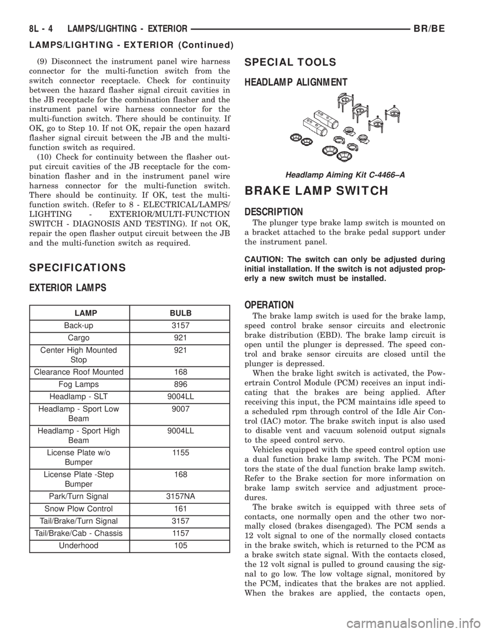
SPECIAL TOOLS
HEADLAMP ALIGNMENT
BRAKE LAMP SWITCH
DESCRIPTION
The plunger type brake lamp switch is mounted on
a bracket attached to the brake pedal support under
the instrument panel.
CAUTION: The switch can only be adjusted during
initial installation. If the switch is not adjusted prop-
erly a new switch must be installed.
OPERATION
The brake lamp switch is used for the brake lamp,
speed control brake sensor circuits and electronic
brake distribution (EBD). The brake lamp circuit is
open until the plunger is depressed. The speed con-
trol and brake sensor circuits are closed until the
plunger is depressed.
When the brake light switch is activated, the Pow-
ertrain Control Module (PCM) receives an input indi-
cating that the brakes are being applied. After
receiving this input, the PCM maintains idle speed to
a scheduled rpm through control of the Idle Air Con-
trol (IAC) motor. The brake switch input is also used
to disable vent and vacuum solenoid output signals
to the speed control servo.
Vehicles equipped with the speed control option use
a dual function brake lamp switch. The PCM moni-
tors the state of the dual function brake lamp switch.
Refer to the Brake section for more information on
brake lamp switch service and adjustment proce-
dures.
The brake switch is equipped with three sets of
contacts, one normally open and the other two nor-
mally closed (brakes disengaged). The PCM sends a
12 volt signal to one of the normally closed contacts
in the brake switch, which is returned to the PCM as
a brake switch state signal. With the contacts closed,
the 12 volt signal is pulled to ground causing the sig-
nal to go low. The low voltage signal, monitored by
the PCM, indicates that the brakes are not applied.
When the brakes are applied, the contacts open,
Headlamp Aiming Kit C-4466±A
8L - 4 LAMPS/LIGHTING - EXTERIORBR/BE
LAMPS/LIGHTING - EXTERIOR (Continued)
Page 604 of 2889
COMBINATION FLASHER
DESCRIPTION
The combination flasher is located in the Junction
Block (JB) behind the fuse access panel on the left
outboard end of the instrument panel. The combina-
tion flasher is a smart relay that functions as both
the turn signal system and the hazard warning sys-
tem flasher. The combination flasher contains active
electronic Integrated Circuitry (IC) elements. This
flasher is designed to handle the current flow
requirements of the factory-installed lighting. If sup-
plemental lighting is added to the turn signal lamp
circuits, such as when towing a trailer with lights,
the combination flasher will automatically try to
compensate to keep the flash rate the same.
The combination flasher has five blade-type termi-
nals that connect it to the vehicle electrical system
through five matching cavities in the receptacle of
the JB. While the combination flasher has a Interna-
tional Standards Organization (ISO)-type relay ter-
minal configuration or footprint, the internal
circuitry is much different. The combination flasher
does not use standard ISO-relay inputs or provide
ISO-relay type outputs or functions. The combination
flasher should never be substituted for an ISO-relay
or replaced with an ISO-relay, or else component and
vehicle damage may occur.
The combination flasher cannot be repaired or
adjusted and, if faulty or damaged, it must be
replaced.
OPERATION
The combination flasher has five blade-type termi-
nals intended for the following inputs and outputs:
fused B(+), fused ignition switch output, ground, turn
signal circuit, and hazard warning circuit. Constant
battery voltage and ground are supplied to the
flasher so that it can perform the hazard warning
function, and ignition switched battery voltage is
supplied for the turn signal function.
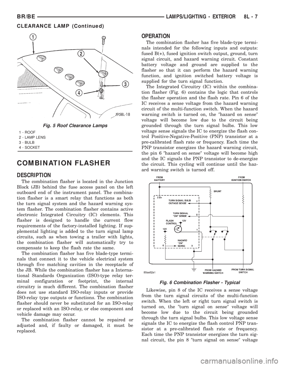
The Integrated Circuitry (IC) within the combina-
tion flasher (Fig. 6) contains the logic that controls
the flasher operation and the flash rate. Pin 6 of the
IC receives a sense voltage from the hazard warning
circuit of the multi-function switch. When the hazard
warning switch is turned on, the9hazard on sense9
voltage will become low due to the circuit being
grounded through the turn signal bulbs. This low
voltage sense signals the IC to energize the flash con-
trol Positive-Negative-Positive (PNP) transistor at a
pre-calibrated flash rate or frequency. Each time the
PNP transistor energizes the hazard warning circuit,
the pin 69hazard on sense9voltage will become high
and the IC signals the PNP transistor to de-energize
the circuit. This cycling will continue until the haz-
ard warning switch is turned off.
Likewise, pin 8 of the IC receives a sense voltage
from the turn signal circuits of the multi-function
switch. When the left or right turn signal switch is
turned on, the9turn signal on sense9voltage will
become low due to the circuit being grounded
through the turn signal bulbs. This low voltage sense
signals the IC to energize the flash control PNP tran-
sistor at a pre-calibrated flash rate or frequency.
Each time the PNP transistor energizes the turn sig-
nal circuit, the pin 89turn signal on sense9voltage
Fig. 5 Roof Clearance Lamps
1 - ROOF
2 - LAMP LENS
3 - BULB
4 - SOCKET
Fig. 6 Combination Flasher - Typical
BR/BELAMPS/LIGHTING - EXTERIOR 8L - 7
CLEARANCE LAMP (Continued)
Page 617 of 2889
INSTALLATION
WARNING: ON VEHICLES EQUIPPED WITH AIR-
BAGS, DISABLE THE AIRBAG SYSTEM BEFORE
ATTEMPTING ANY STEERING WHEEL, STEERING
COLUMN, OR INSTRUMENT PANEL COMPONENT
DIAGNOSIS OR SERVICE. DISCONNECT AND ISO-
LATE THE BATTERY NEGATIVE (GROUND) CABLE,
THEN WAIT TWO MINUTES FOR THE AIRBAG SYS-
TEM CAPACITOR TO DISCHARGE BEFORE PER-
FORMING FURTHER DIAGNOSIS OR SERVICE. THIS
IS THE ONLY SURE WAY TO DISABLE THE AIRBAG
SYSTEM. FAILURE TO TAKE THE PROPER PRE-
CAUTIONS COULD RESULT IN ACCIDENTAL AIR-
BAG DEPLOYMENT AND POSSIBLE PERSONAL
INJURY.
(1) Position the headlamp switch to the instru-
ment panel.
(2) Reconnect the two instrument panel wire har-
ness connectors for the headlamp switch to the con-
nector receptacles on the back of the switch.
(3) Position the headlamp switch into the instru-
ment panel.
(4) Install and tighten the three screws that secure
the headlamp switch to the instrument panel.
Tighten the screws to 2.2 N´m (20 in. lbs.).
(5) Reinstall the cluster bezel onto the instrument
panel. (Refer to 23 - BODY/INSTRUMENT PANEL/
CLUSTER BEZEL - INSTALLATION).
(6) Connect the battery negative cable.
HEADLAMP UNIT
REMOVAL
(1) Disconnect and isolate the battery negative
cable.
(2) Remove push-in fastener attaching seal to radi-
ator closure panel.
(3) Remove park and turn signal lamp.
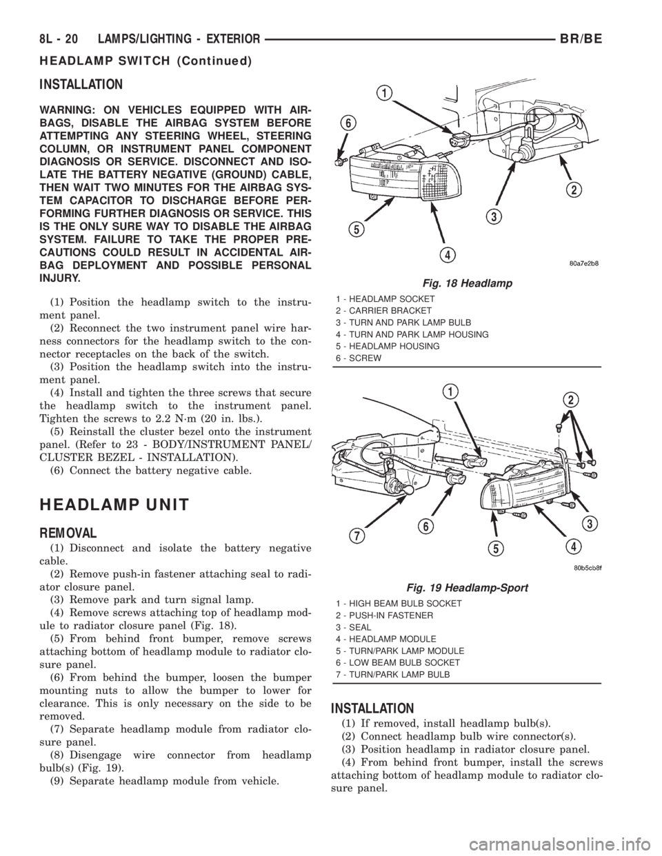
(4) Remove screws attaching top of headlamp mod-
ule to radiator closure panel (Fig. 18).
(5) From behind front bumper, remove screws
attaching bottom of headlamp module to radiator clo-
sure panel.
(6) From behind the bumper, loosen the bumper
mounting nuts to allow the bumper to lower for
clearance. This is only necessary on the side to be
removed.
(7) Separate headlamp module from radiator clo-
sure panel.
(8) Disengage wire connector from headlamp
bulb(s) (Fig. 19).
(9) Separate headlamp module from vehicle.
INSTALLATION
(1) If removed, install headlamp bulb(s).
(2) Connect headlamp bulb wire connector(s).
(3) Position headlamp in radiator closure panel.
(4) From behind front bumper, install the screws
attaching bottom of headlamp module to radiator clo-
sure panel.
Fig. 18 Headlamp
1 - HEADLAMP SOCKET
2 - CARRIER BRACKET
3 - TURN AND PARK LAMP BULB
4 - TURN AND PARK LAMP HOUSING
5 - HEADLAMP HOUSING
6 - SCREW
Fig. 19 Headlamp-Sport
1 - HIGH BEAM BULB SOCKET
2 - PUSH-IN FASTENER
3 - SEAL
4 - HEADLAMP MODULE
5 - TURN/PARK LAMP MODULE
6 - LOW BEAM BULB SOCKET
7 - TURN/PARK LAMP BULB
8L - 20 LAMPS/LIGHTING - EXTERIORBR/BE
HEADLAMP SWITCH (Continued)
Page 808 of 2889

8W-15 GROUND DISTRIBUTION
Component Page
A/C Compressor Clutch............... 8W-15-10, 8
A/C-Heater Control.................... 8W-15-14
A/C Heater Temperature Select........... 8W-15-12
Aftermarket Trailer Tow Connector......... 8W-15-6
Airbag Control Module.................. 8W-15-5
Ash Receiver Lamp.................... 8W-15-14
Automatic Day/Night Mirror............. 8W-15-13
Auxiliary Battery..................... 8W-15-11
Battery............................ 8W-15-11
Blend Door Actuator................... 8W-15-12
Blower Motor Relay.................... 8W-15-2
Brake Lamp Switch................... 8W-15-12
Brake Pressure Switch.................. 8W-15-3
Center High Mounted Stop Lamp No. 1..... 8W-15-17
Center High Mounted Stop Lamp No. 2..... 8W-15-17
Center Identification Lamp.............. 8W-15-18
Central Timer Module C1............... 8W-15-12
Central Timer Module C2............... 8W-15-13
Cigar Lighter........................ 8W-15-14
Clockspring.......................... 8W-15-4
Combination Flasher.................. 8W-15-13
Controller Antilock Brake................ 8W-15-5
Cummins Bus....................... 8W-15-10
Cup Holder Lamp..................... 8W-15-14
Data Link Connector.............. 8W-15-8, 10, 12
Daytime Running Lamp Module......... 8W-15-2, 3
Driver Cylinder Lock Switch............. 8W-15-16
Driver Door Ajar Switch................ 8W-15-16
Driver Door Window/Lock Switch....... 8W-15-16, 17
Driver Heated Seat Cushion............. 8W-15-15
Driver Heated Seat Switch.............. 8W-15-13
Driver Power Seat Switch............ 8W-15-15, 17
Electric Brake Provision................ 8W-15-14
Engine Control Module.................. 8W-15-9
Engine Starter Motor Relay............. 8W-15-8, 9
Fuel Heater Relay..................... 8W-15-2
Fuel Heater......................... 8W-15-10
Fuel Injection Pump.................... 8W-15-9
Fuel Pump Module..................... 8W-15-7
Fuel Pump Relay...................... 8W-15-2
Fuel Transfer Pump................... 8W-15-10
G100.......................... 8W-15-12, 5, 7
G101............................... 8W-15-5
G102............................... 8W-15-2
G105............................... 8W-15-8
G107.............................. 8W-15-10
G113 .............................. 8W-15-11
G114 .............................. 8W-15-11
G115 .............................. 8W-15-11
G116 .............................. 8W-15-11
G117 .............................. 8W-15-11
G118 .............................. 8W-15-11
G120.............................. 8W-15-11
G200......................... 8W-15-7, 12, 14
G201........................... 8W-15-12, 14
G300.............................. 8W-15-16
G301.............................. 8W-15-17
G302.............................. 8W-15-18
Glove Box Lamp And Switch............. 8W-15-14
Headlamp Beam Select Switch............ 8W-15-14
Headlamp Switch.................. 8W-15-13, 14
Heated Mirror Switch.................. 8W-15-13
High Note Horn....................... 8W-15-7
Ignition Switch....................... 8W-15-13
Instrument Cluster................. 8W-15-12, 14
Intake Air Heater Relay No. 1............. 8W-15-9Component Page
Intake Air Heater Relay No. 2............. 8W-15-9
Joint Connector No. 1................... 8W-15-2
Joint Connector No. 2................... 8W-15-9
Joint Connector No. 3................... 8W-15-7
Joint Connector No. 4................... 8W-15-3
Joint Connector No. 5.................. 8W-15-13
Joint Connector No. 6................... 8W-15-4
Joint Connector No. 8................ 8W-15-13, 5
Junction Block.................... 8W-15-12, 13
Left Back-Up Lamp.................... 8W-15-6
Left Front Door Speaker................. 8W-15-4
Left Front Fender Lamp................. 8W-15-6
Left License Lamp..................... 8W-15-6
Left Outboard Clearance Lamp........... 8W-15-18
Left Outboard Identification Lamp......... 8W-15-18
Left Park/Turn Signal Lamp.............. 8W-15-3
Left Power Mirror..................... 8W-15-16
Left Rear Fender Lamp................. 8W-15-6
Left Remote Radio Switch................ 8W-15-4
Left Tail/Stop/Turn Signal Lamp........... 8W-15-6
Left Visor/Vanity Lamp................. 8W-15-13
Low Note Horn....................... 8W-15-7
Overdrive Switch..................... 8W-15-12
Overhead Console..................... 8W-15-12
Oxygen Sensor 1/2 Left Bank Down......... 8W-15-8
Oxygen Sensor 1/2 Pre-Catalyst............ 8W-15-8
Oxygen Sensor 1/3 Post-Catalyst........... 8W-15-8
Oxygen Sensor 2/2 Right Bank Down........ 8W-15-8
Passenger Airbag On/Off Switch........... 8W-15-5
Passenger Cylinder Lock Switch.......... 8W-15-16
Passenger Door Ajar Switch.............. 8W-15-16
Passenger Door Window/Lock Switch....... 8W-15-16
Passenger Heated Seat Cushion........... 8W-15-15
Passenger Heated Seat Switch............ 8W-15-13
Passenger Power Seat Switch............ 8W-15-15
Power Distribution Center............... 8W-15-2
Power Mirror Switch................... 8W-15-16
Power Outlet........................ 8W-15-14
Powertrain Control Module............ 8W-15-8 , 10
Quad High Beam Relay................. 8W-15-2
Radio Choke Relay..................... 8W-15-4
Radio.............................. 8W-15-5
Right Back-Up Lamp................... 8W-15-6
Right Front Door Speaker................ 8W-15-4
Right Front Fender Lamp................ 8W-15-6
Right License Lamp.................... 8W-15-6
Right Outboard Clearance Lamp.......... 8W-15-18
Right Outboard Identification Lamp........ 8W-15-18
Right Park/Turn Signal Lamp............. 8W-15-7
Right Power Mirror................... 8W-15-16
Right Rear Fender Lamp................ 8W-15-6
Right Remote Radio Switch............... 8W-15-4
Right Tail/Stop/Turn Signal Lamp.......... 8W-15-6
Right Visor/Vanity Lamp................ 8W-15-13
Seat Belt Switch................... 8W-15-15, 17
Seat Heat Interface Module.............. 8W-15-15
Security Relay........................ 8W-15-2
Speed Control Servo.................... 8W-15-3
Tailgate Lamp........................ 8W-15-6
Trailer Tow Connector.................. 8W-15-6
Trailer Tow Relay...................... 8W-15-2
Underhood Lamp...................... 8W-15-3
Washer Fluid Level Switch............... 8W-15-3
Windshield Washer Pump................ 8W-15-7
Wiper Motor......................... 8W-15-7
BR/BE8W-15 GROUND DISTRIBUTION 8W - 15 - 1
Page 1065 of 2889

JUNCTION BLOCK C1 - BLUE 15 WAY
CAV CIRCUIT FUNCTION
1- -
2 G31 20VT/LG AMBIENT TEMPERATURE SENSOR SIGNAL
3 A20 20RD/DB FUSED IGNITION SWITCH OUTPUT (RUN)
4 L61 18LG LEFT TURN SIGNAL
5 V6 16DB FUSED IGNITION SWITCH OUTPUT (RUN-ACC)
6- -
7- -
8- -
9 L7 18BK/YL PARK LAMP RELAY OUTPUT
10 F18 20LG/BK FUSED IGNITION SWITCH OUTPUT (RUN-START)
11 L1 18VT/BK BACK-UP LAMP FEED
12 V6 16DB FUSED IGNITION SWITCH OUTPUT (RUN-ACC)
13 V6 16DB FUSED IGNITION SWITCH OUTPUT (RUN-ACC)
14 G32 20BK/VT SENSOR GROUND
15 - -
JUNCTION BLOCK C2 - NATURAL 6 WAY
CAV CIRCUIT FUNCTION
1 A7 10RD/BK FUSED B(+)
2 L9 16BK/VT FUSED FLASHER FEED
3 M1 20PK FUSED B(+)
4- -
5 L60 18TN RIGHT TURN SIGNAL
6- -
JUNCTION BLOCK C3 - 14 WAY
CAV CIRCUIT FUNCTION
1 G32 22BK/LB SENSOR GROUND
2 Z2 20BK/LG GROUND
3 M2 22YL COURTESY LAMPS DRIVER
4- -
5 G31 22VT/LG AMBIENT TEMPERATURE SENSOR SIGNAL
6 M1 22PK (BASE) FUSED B(+)
6 M1 20PK (HIGHLINE) FUSED B(+)
7- -
8 L7 18BK/YL (CLEARANCE/ID LAMPS) PARK LAMP RELAY OUTPUT
9- -
10 - -
11 L1 20VT/BK BACK-UP LAMP FEED
12 - -
13 Z3 18BK (HIGHLINE) GROUND
14 F12 20DB/WT (HIGHLINE) FUSED IGNITION SWITCH OUTPUT (RUN-START)
8W - 80 - 52 8W-80 CONNECTOR PIN-OUTSBR/BE