2001 DODGE RAM four wheel drive
[x] Cancel search: four wheel drivePage 43 of 2889
²Do not tow a vehicle in a manner that could
jeopardize the safety of the operator, pedestrians or
other motorists.
²Do not attach tow chains, T-hooks, J-hooks, or a
tow sling to a bumper, steering linkage, drive shafts
or a non-reinforced frame hole.
²Do not tow a heavily loaded vehicle. Damage to
the cab, cargo box or frame may result. Use a flatbed
device to transport a loaded vehicle.
GROUND CLEARANCE
CAUTION: If vehicle is towed with wheels removed,
install lug nuts to retain brake drums or rotors.
A towed vehicle should be raised until lifted wheels
are a minimum 100 mm (4 in) from the ground. Be
sure there is adequate ground clearance at the oppo-
site end of the vehicle, especially when towing over
rough terrain or steep rises in the road. If necessary,
remove the wheels from the lifted end of the vehicle
and lower the vehicle closer to the ground, to
increase the ground clearance at the opposite end of
the vehicle. Install lug nuts on wheel attaching studs
to retain brake drums or rotors.
RAMP ANGLE
If a vehicle with flat-bed towing equipment is used,
the approach ramp angle should not exceed 15
degrees.
TOWING WHEN KEYS ARE NOT AVAILABLE
When the vehicle is locked and keys are not avail-
able, use a flat bed hauler. A Wheel-lift or Sling-type
device can be used on 4WD vehicles providedall the
wheels are lifted off the ground using tow dol-
lies.
FOUR-WHEEL-DRIVE VEHICLE TOWING
Chrysler Corporation recommends that a vehicle be
transported on a flat-bed device. A Wheel-lift or
Sling-type device can be used providedall the
wheels are lifted off the ground using tow dol-
lies.
WARNING: WHEN TOWING A DISABLED VEHICLE
AND THE DRIVE WHEELS ARE SECURED IN A
WHEEL LIFT OR TOW DOLLIES, ENSURE THE
TRANSMISSION IS IN THE PARK POSITION (AUTO-
MATIC TRANSMISSION) OR A FORWARD DRIVE
GEAR (MANUAL TRANSMISSION).
CAUTION: Many vehicles are equipped with air
dams, spoilers, and/or ground effect panels. To
avoid component damage, a wheel-lift towing vehi-
cle or a flat-bed hauling vehicle is recommended.
0 - 30 LUBRICATION & MAINTENANCEBR/BE
TOWING (Continued)
Page 77 of 2889
DRIVELINE VIBRATION
Drive Condition Possible Cause Correction
Propeller Shaft Noise 1) Undercoating or other foreign
material on shaft.1) Clean exterior of shaft and wash
with solvent.
2) Loose U-joint clamp screws. 2) Install new clamps and screws
and tighten to proper torque.
3) Loose or bent U-joint yoke or
excessive runout.3) Install new yoke.
4) Incorrect driveline angularity. 4) Measure and correct driveline
angles.
5) Rear spring center bolt not in
seat.5) Loosen spring u-bolts and seat
center bolt.
6) Worn U-joint bearings. 6) Install new U-joint.
7) Propeller shaft damaged or out
of balance.7) Installl new propeller shaft.
8) Broken rear spring. 8) Install new rear spring.
9) Excessive runout or unbalanced
condition.9) Re-index propeller shaft, test,
and evaluate.
10) Excessive drive pinion gear
shaft runout.10) Re-index propeller shaft and
evaluate.
11) Excessive axle yoke deflection. 11) Inspect and replace yoke if
necessary.
12) Excessive transfer case runout. 12) Inspect and repair as necessary.
Universal Joint Noise 1) Loose U-joint clamp screws. 1) Install new clamps and screws
and tighten to proper torque.
2) Lack of lubrication. 2) Replace as U-joints as
necessary.
BALANCE
NOTE: Removing and re-indexing the propeller
shaft 180É relative to the yoke may eliminate some
vibrations.
If propeller shaft is suspected of being unbalanced,
it can be verified with the following procedure:
(1) Raise the vehicle.
(2) Clean all the foreign material from the propel-
ler shaft and the universal joints.
(3) Inspect the propeller shaft for missing balance
weights, broken welds, and bent areas.If the pro-
peller shaft is bent, it must be replaced.
(4) Inspect the universal joints to ensure that they
are not worn, are properly installed, and are cor-
rectly aligned with the shaft.
(5) Check the universal joint clamp screws torque.
(6) Remove the wheels and tires. Install the wheel
lug nuts to retain the brake drums or rotors.
(7) Mark and number the shaft six inches from the
yoke end at four positions 90É apart.(8) Run and accelerate the vehicle until vibration
occurs. Note the intensity and speed the vibration
occurred. Stop the engine.
(9) Install a screw clamp at position 1 (Fig. 6).
(10) Start the engine and re-check for vibration. If
there is little or no change in vibration, move the
clamp to one of the other three positions. Repeat the
vibration test.
(11) If there is no difference in vibration at the
other positions, the source of the vibration may not
be propeller shaft.
(12) If the vibration decreased, install a second
clamp (Fig. 7) and repeat the test.
(13) If the additional clamp causes an additional
vibration, separate the clamps (1/2 inch above and
below the mark). Repeat the vibration test (Fig. 8).
(14) Increase distance between the clamp screws
and repeat the test until the amount of vibration is
at the lowest level. Bend the slack end of the clamps
so the screws will not loosen.
3 - 4 PROPELLER SHAFTBR/BE
PROPELLER SHAFT (Continued)
Page 103 of 2889
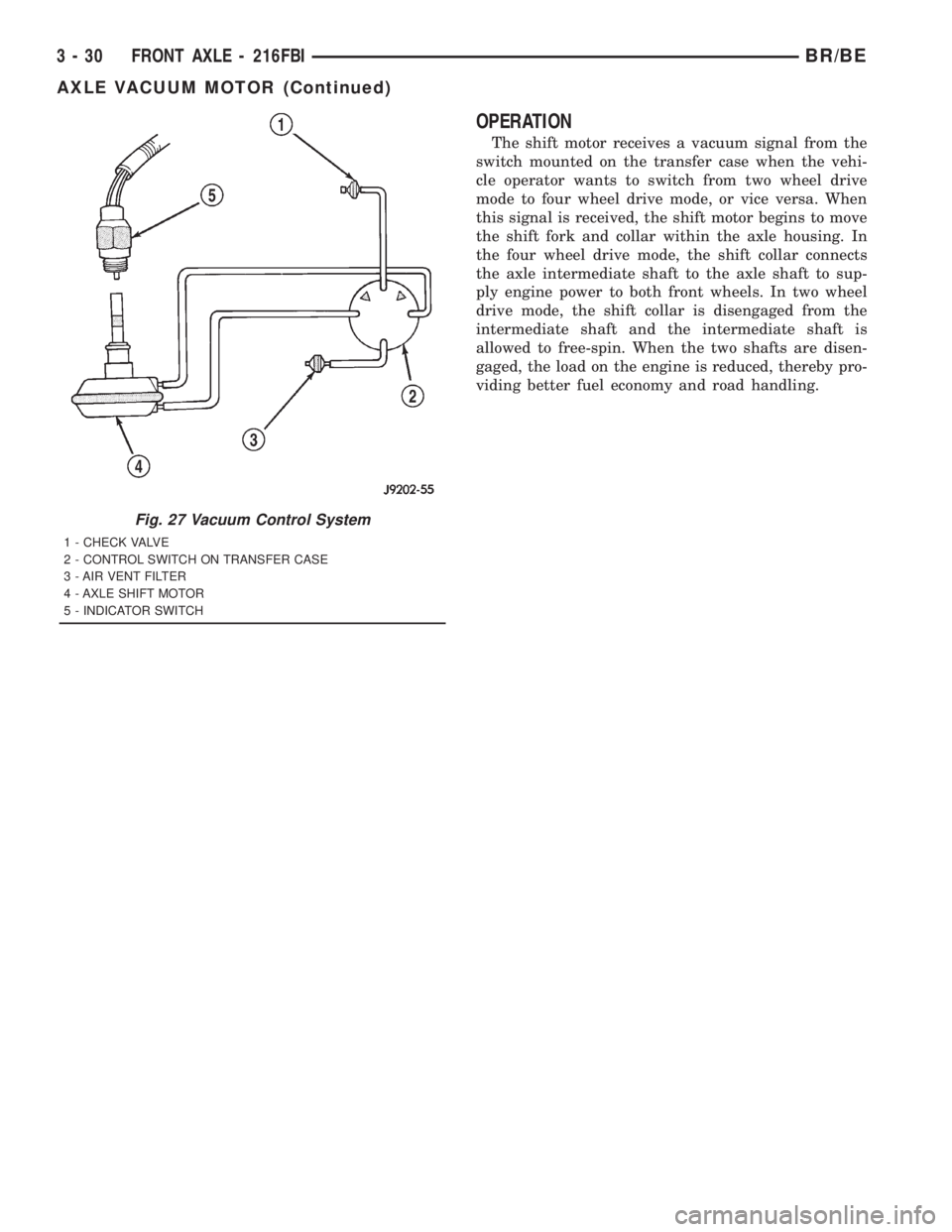
OPERATION
The shift motor receives a vacuum signal from the
switch mounted on the transfer case when the vehi-
cle operator wants to switch from two wheel drive
mode to four wheel drive mode, or vice versa. When
this signal is received, the shift motor begins to move
the shift fork and collar within the axle housing. In
the four wheel drive mode, the shift collar connects
the axle intermediate shaft to the axle shaft to sup-
ply engine power to both front wheels. In two wheel
drive mode, the shift collar is disengaged from the
intermediate shaft and the intermediate shaft is
allowed to free-spin. When the two shafts are disen-
gaged, the load on the engine is reduced, thereby pro-
viding better fuel economy and road handling.
Fig. 27 Vacuum Control System
1 - CHECK VALVE
2 - CONTROL SWITCH ON TRANSFER CASE
3 - AIR VENT FILTER
4 - AXLE SHIFT MOTOR
5 - INDICATOR SWITCH
3 - 30 FRONT AXLE - 216FBIBR/BE
AXLE VACUUM MOTOR (Continued)
Page 107 of 2889
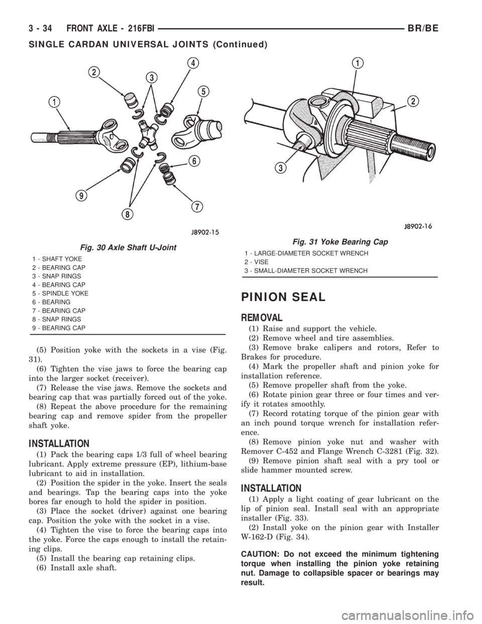
(5) Position yoke with the sockets in a vise (Fig.
31).
(6) Tighten the vise jaws to force the bearing cap
into the larger socket (receiver).
(7) Release the vise jaws. Remove the sockets and
bearing cap that was partially forced out of the yoke.
(8) Repeat the above procedure for the remaining
bearing cap and remove spider from the propeller
shaft yoke.
INSTALLATION
(1) Pack the bearing caps 1/3 full of wheel bearing
lubricant. Apply extreme pressure (EP), lithium-base
lubricant to aid in installation.
(2) Position the spider in the yoke. Insert the seals
and bearings. Tap the bearing caps into the yoke
bores far enough to hold the spider in position.
(3) Place the socket (driver) against one bearing
cap. Position the yoke with the socket in a vise.
(4) Tighten the vise to force the bearing caps into
the yoke. Force the caps enough to install the retain-
ing clips.
(5) Install the bearing cap retaining clips.
(6) Install axle shaft.
PINION SEAL
REMOVAL
(1) Raise and support the vehicle.
(2) Remove wheel and tire assemblies.
(3) Remove brake calipers and rotors, Refer to
Brakes for procedure.
(4) Mark the propeller shaft and pinion yoke for
installation reference.
(5) Remove propeller shaft from the yoke.
(6) Rotate pinion gear three or four times and ver-
ify it rotates smoothly.
(7) Record rotating torque of the pinion gear with
an inch pound torque wrench for installation refer-
ence.
(8) Remove pinion yoke nut and washer with
Remover C-452 and Flange Wrench C-3281 (Fig. 32).
(9) Remove pinion shaft seal with a pry tool or
slide hammer mounted screw.
INSTALLATION
(1) Apply a light coating of gear lubricant on the
lip of pinion seal. Install seal with an appropriate
installer (Fig. 33).
(2) Install yoke on the pinion gear with Installer
W-162-D (Fig. 34).
CAUTION: Do not exceed the minimum tightening
torque when installing the pinion yoke retaining
nut. Damage to collapsible spacer or bearings may
result.
Fig. 30 Axle Shaft U-Joint
1 - SHAFT YOKE
2 - BEARING CAP
3 - SNAP RINGS
4 - BEARING CAP
5 - SPINDLE YOKE
6 - BEARING
7 - BEARING CAP
8 - SNAP RINGS
9 - BEARING CAP
Fig. 31 Yoke Bearing Cap
1 - LARGE-DIAMETER SOCKET WRENCH
2 - VISE
3 - SMALL-DIAMETER SOCKET WRENCH
3 - 34 FRONT AXLE - 216FBIBR/BE
SINGLE CARDAN UNIVERSAL JOINTS (Continued)
Page 135 of 2889
AXLE VACUUM MOTOR
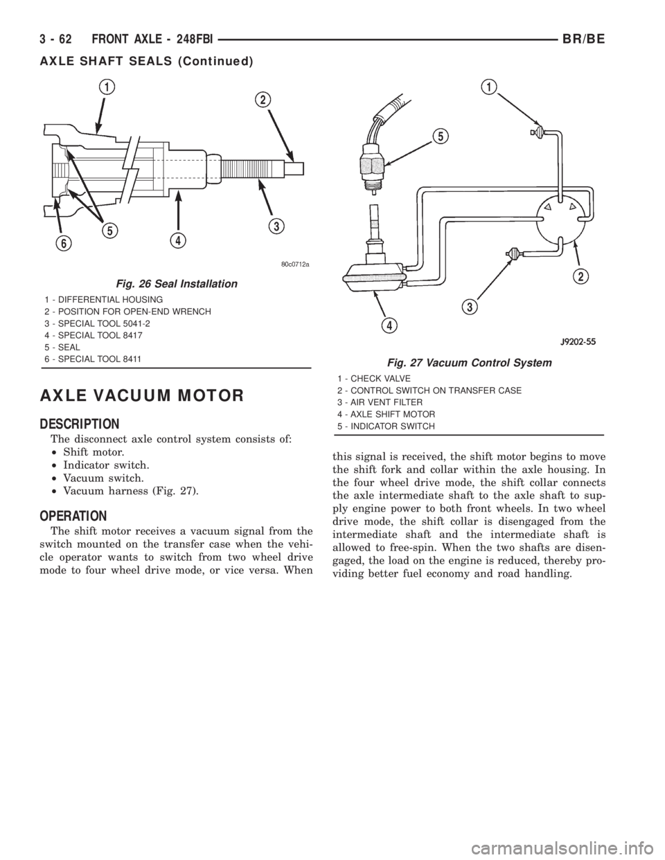
DESCRIPTION
The disconnect axle control system consists of:
²Shift motor.
²Indicator switch.
²Vacuum switch.
²Vacuum harness (Fig. 27).
OPERATION
The shift motor receives a vacuum signal from the
switch mounted on the transfer case when the vehi-
cle operator wants to switch from two wheel drive
mode to four wheel drive mode, or vice versa. Whenthis signal is received, the shift motor begins to move
the shift fork and collar within the axle housing. In
the four wheel drive mode, the shift collar connects
the axle intermediate shaft to the axle shaft to sup-
ply engine power to both front wheels. In two wheel
drive mode, the shift collar is disengaged from the
intermediate shaft and the intermediate shaft is
allowed to free-spin. When the two shafts are disen-
gaged, the load on the engine is reduced, thereby pro-
viding better fuel economy and road handling.
Fig. 26 Seal Installation
1 - DIFFERENTIAL HOUSING
2 - POSITION FOR OPEN-END WRENCH
3 - SPECIAL TOOL 5041-2
4 - SPECIAL TOOL 8417
5 - SEAL
6 - SPECIAL TOOL 8411
Fig. 27 Vacuum Control System
1 - CHECK VALVE
2 - CONTROL SWITCH ON TRANSFER CASE
3 - AIR VENT FILTER
4 - AXLE SHIFT MOTOR
5 - INDICATOR SWITCH
3 - 62 FRONT AXLE - 248FBIBR/BE
AXLE SHAFT SEALS (Continued)
Page 139 of 2889
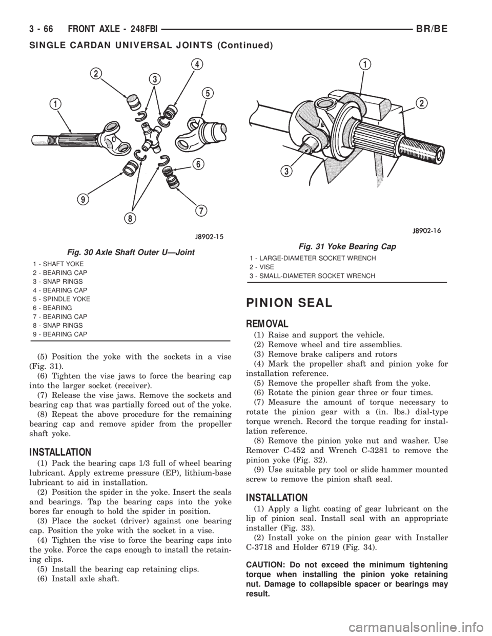
(5) Position the yoke with the sockets in a vise
(Fig. 31).
(6) Tighten the vise jaws to force the bearing cap
into the larger socket (receiver).
(7) Release the vise jaws. Remove the sockets and
bearing cap that was partially forced out of the yoke.
(8) Repeat the above procedure for the remaining
bearing cap and remove spider from the propeller
shaft yoke.
INSTALLATION
(1) Pack the bearing caps 1/3 full of wheel bearing
lubricant. Apply extreme pressure (EP), lithium-base
lubricant to aid in installation.
(2) Position the spider in the yoke. Insert the seals
and bearings. Tap the bearing caps into the yoke
bores far enough to hold the spider in position.
(3) Place the socket (driver) against one bearing
cap. Position the yoke with the socket in a vise.
(4) Tighten the vise to force the bearing caps into
the yoke. Force the caps enough to install the retain-
ing clips.
(5) Install the bearing cap retaining clips.
(6) Install axle shaft.
PINION SEAL
REMOVAL
(1) Raise and support the vehicle.
(2) Remove wheel and tire assemblies.
(3) Remove brake calipers and rotors
(4) Mark the propeller shaft and pinion yoke for
installation reference.
(5) Remove the propeller shaft from the yoke.
(6) Rotate the pinion gear three or four times.
(7) Measure the amount of torque necessary to
rotate the pinion gear with a (in. lbs.) dial-type
torque wrench. Record the torque reading for instal-
lation reference.
(8) Remove the pinion yoke nut and washer. Use
Remover C-452 and Wrench C-3281 to remove the
pinion yoke (Fig. 32).
(9) Use suitable pry tool or slide hammer mounted
screw to remove the pinion shaft seal.
INSTALLATION
(1) Apply a light coating of gear lubricant on the
lip of pinion seal. Install seal with an appropriate
installer (Fig. 33).
(2) Install yoke on the pinion gear with Installer
C-3718 and Holder 6719 (Fig. 34).
CAUTION: Do not exceed the minimum tightening
torque when installing the pinion yoke retaining
nut. Damage to collapsible spacer or bearings may
result.
Fig. 30 Axle Shaft Outer UÐJoint
1 - SHAFT YOKE
2 - BEARING CAP
3 - SNAP RINGS
4 - BEARING CAP
5 - SPINDLE YOKE
6 - BEARING
7 - BEARING CAP
8 - SNAP RINGS
9 - BEARING CAP
Fig. 31 Yoke Bearing Cap
1 - LARGE-DIAMETER SOCKET WRENCH
2 - VISE
3 - SMALL-DIAMETER SOCKET WRENCH
3 - 66 FRONT AXLE - 248FBIBR/BE
SINGLE CARDAN UNIVERSAL JOINTS (Continued)
Page 198 of 2889
AXLE SHAFTS
REMOVAL
(1) Remove the axle shaft flange bolts.
(2) Slide the axle shaft out from the axle tube.
INSTALLATION
(1) Clean the gasket contact surface area on the
flange with an appropriate solvent. Install a new
flange gasket and slide the axle shaft into the tube.
(2) Install the bolts and tighten to 129 N´m (95 ft.
lbs.).
AXLE BEARINGS
REMOVAL
(1) Remove wheel and tire assembly.
(2) Remove brake drum.
(3) Remove the axle shaft.
(4) Remove the lock wedge and adjustment nut.
Use Socket DD-1241±JD to remove the adjustment
nut.
(5) Remove the hub assembly. The outer axle bear-
ing will slide out as the hub is being removed.
(6) Remove inner grease seal and discard. Use
Installer 5064 and Handle C-4171 to drive grease
seal and inner axle bearing from the hub.
(7) Remove the bearing cups from the hub bore.
Use a brass drift, or an appropriate removal tool, to
tap out the cups.
INSTALLATION
(1) Thoroughly clean both axle bearings and inte-
rior of the hub with an appropriate cleaning solvent.
(2) Install bearing cups with Installer 8151 and
Handle C-4171.
(3)Pack inner and outer bearings with
Mopar wheel bearing grease or equivalent.
(4) Apply grease to inner and outer bearing cup
surfaces.
(5) Install inner axle bearing in the hub.
(6) Installnewgrease seal in hub with Installer
8149 and Handle C-4171.(7) Inspect bearing and seal contact surfaces on
the axle tube for burrs/roughness. Remove all the
rough contact surfaces from the axle tube.
(8) Carefully slide the hub onto the axle.
CAUTION: Do not let grease seal contact axle tube
threads during installtion.
(9) Install outer axle bearing.
(10) Install hub bearing adjustment nut with
Socket DD-1241±JD.
(11) Tighten adjustment nut to 163-190 N´m (120-
140 ft. lbs.) while rotating the wheel. Then loosen
adjustment nut 1/8 to 1/3 of-a-turn to provide 0.025-
0.250mm (0.001-0.009 in.) wheel bearing end play.
(12) Tap locking wedge into the spindle keyway
and adjustment nut.
NOTE: Located locking wedge in a new position in
the adjustment nut.
(13) Install axle shaft and brake drum.
(14) Install the wheel and tire assembly.
PINION SEAL
REMOVAL
(1) Raise and support the vehicle.
(2) Scribe a mark on the universal joint, pinion
yoke, and pinion shaft for reference.
(3) Disconnect the propeller shaft from the pinion
yoke. Secure the propeller shaft in an upright posi-
tion to prevent damage to the rear universal joint.
(4) Remove the wheel and tire assemblies.
(5) Remove the brake drums to prevent any drag.
The drag may cause a false bearing preload torque
measurement.
(6) Rotate the pinion yoke three or four times.
(7) Measure the amount of torque necessary to
rotate the pinion gear with a (in. lbs.) dial-type
torque wrench. Record the torque reading for instal-
lation reference.
(8) Hold the yoke with Wrench 6719. Remove the
pinion shaft nut and washer.
(9) Remove the yoke with Remover C-452 (Fig. 22).
(10) Remove the pinion shaft seal with suitable
pry tool or slide-hammer mounted screw.
INSTALLATION
NOTE: The outer perimeter of the seal is pre-coated
with a special sealant. An additional application of
sealant is not required.
(1) Apply a light coating of gear lubricant on the
lip of pinion seal.
Arbor Discs 6732
BR/BEREAR AXLE - 248RBI 3 - 125
REAR AXLE - 248RBI (Continued)
Page 229 of 2889
AXLE SHAFTS
REMOVAL
(1) Remove the axle shaft flange bolts.
(2) Slide the axle shaft out from the axle tube.
INSTALLATION
(1) Clean the gasket contact surface area on the
flange with an appropriate solvent. Install a new
flange gasket and slide the axle shaft into the tube.
(2) Install the bolts and tighten to 129 N´m (95 ft.
lbs.).
AXLE BEARINGS
REMOVAL
(1) Remove wheel and tire assembly.
(2) Remove brake drum.
(3) Remove the axle shaft.
(4) Remove the lock wedge and adjustment nut.
Use Socket DD-1241±JD to remove the adjustment
nut.
(5) Remove the hub assembly. The outer axle bear-
ing will slide out as the hub is being removed.
(6) Remove inner grease seal and discard. Use
Installer 5064 and Handle C-4171 to drive grease
seal and inner axle bearing from the hub.
(7) Remove the bearing cups from the hub bore.
Use a brass drift, or an appropriate removal tool, to
tap out the cups.
INSTALLATION
(1) Thoroughly clean both axle bearings and inte-
rior of the hub with an appropriate cleaning solvent.
(2) Install bearing cups with Installer 8151 and
Handle C-4171.
(3)Pack inner and outer bearings with
Mopar wheel bearing grease or equivalent.
(4) Apply grease to inner and outer bearing cup
surfaces.
(5) Install inner axle bearing in the hub.
(6) Installnewgrease seal in hub with Installer
8149 and Handle C-4171.
(7) Inspect bearing and seal contact surfaces on
the axle tube for burrs/roughness. Remove all the
rough contact surfaces from the axle tube.
(8) Carefully slide the hub onto the axle.
CAUTION: Do not let grease seal contact axle tube
threads during installtion.
(9) Install outer axle bearing.
(10) Install hub bearing adjustment nut with
Socket DD-1241±JD.(11) Tighten adjustment nut to 163-190 N´m (120-
140 ft. lbs.) while rotating the wheel. Then loosen
adjustment nut 1/8 to 1/3 of-a-turn to provide 0.025-
0.250mm (0.001-0.009 in.) wheel bearing end play.
(12) Tap locking wedge into the spindle keyway
and adjustment nut.
NOTE: Located locking wedge in a new position in
the adjustment nut.
(13) Install axle shaft and brake drum.
(14) Install the wheel and tire assembly.
PINION SEAL
REMOVAL
(1) Raise and support the vehicle.
(2) Scribe a mark on the universal joint, pinion
yoke, and pinion shaft for reference.
(3) Disconnect the propeller shaft from the pinion
yoke. Secure the propeller shaft in an upright posi-
tion to prevent damage to the rear universal joint.
(4) Remove the wheel and tire assemblies.
(5) Remove the brake drums to prevent any drag.
The drag may cause a false bearing preload torque
measurement.
(6) Rotate the pinion yoke three or four times.
(7) Measure the amount of torque necessary to
rotate the pinion gear with a (in. lbs.) dial-type
torque wrench. Record the torque reading for instal-
lation reference.
(8) Hold the yoke with Wrench 6719. Remove the
pinion shaft nut and washer.
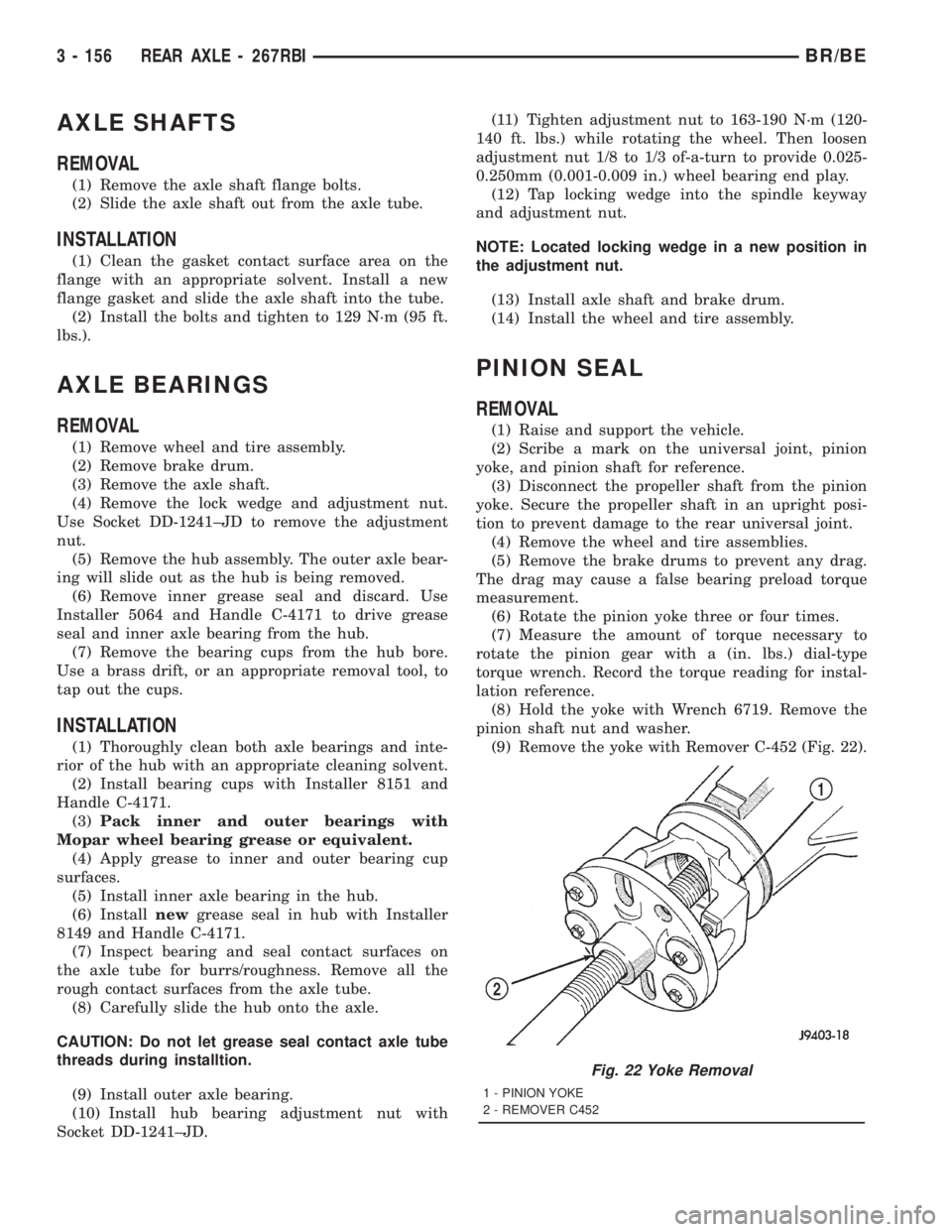
(9) Remove the yoke with Remover C-452 (Fig. 22).
Fig. 22 Yoke Removal
1 - PINION YOKE
2 - REMOVER C452
3 - 156 REAR AXLE - 267RBIBR/BE