2001 DODGE RAM display
[x] Cancel search: displayPage 2 of 2889
INTRODUCTION
TABLE OF CONTENTS
page page
BODY CODE PLATE
DESCRIPTION............................1
FASTENER IDENTIFICATION
DESCRIPTION............................3
FASTENER USAGE
DESCRIPTION............................6
INTERNATIONAL VEHICLE CONTROL &
DISPLAY SYMBOLS
DESCRIPTION............................6
METRIC SYSTEM
DESCRIPTION............................6TORQUE REFERENCES
DESCRIPTION............................9
VECI LABEL
DESCRIPTION...........................10
OPERATION.............................10
VEHICLE IDENTIFICATION NUMBER
DESCRIPTION...........................10
VEHICLE SAFETY CERTIFICATION LABEL
DESCRIPTION...........................12
EQUIPMENT IDENTIFICATION PLATE
DESCRIPTION...........................12
BODY CODE PLATE
DESCRIPTION
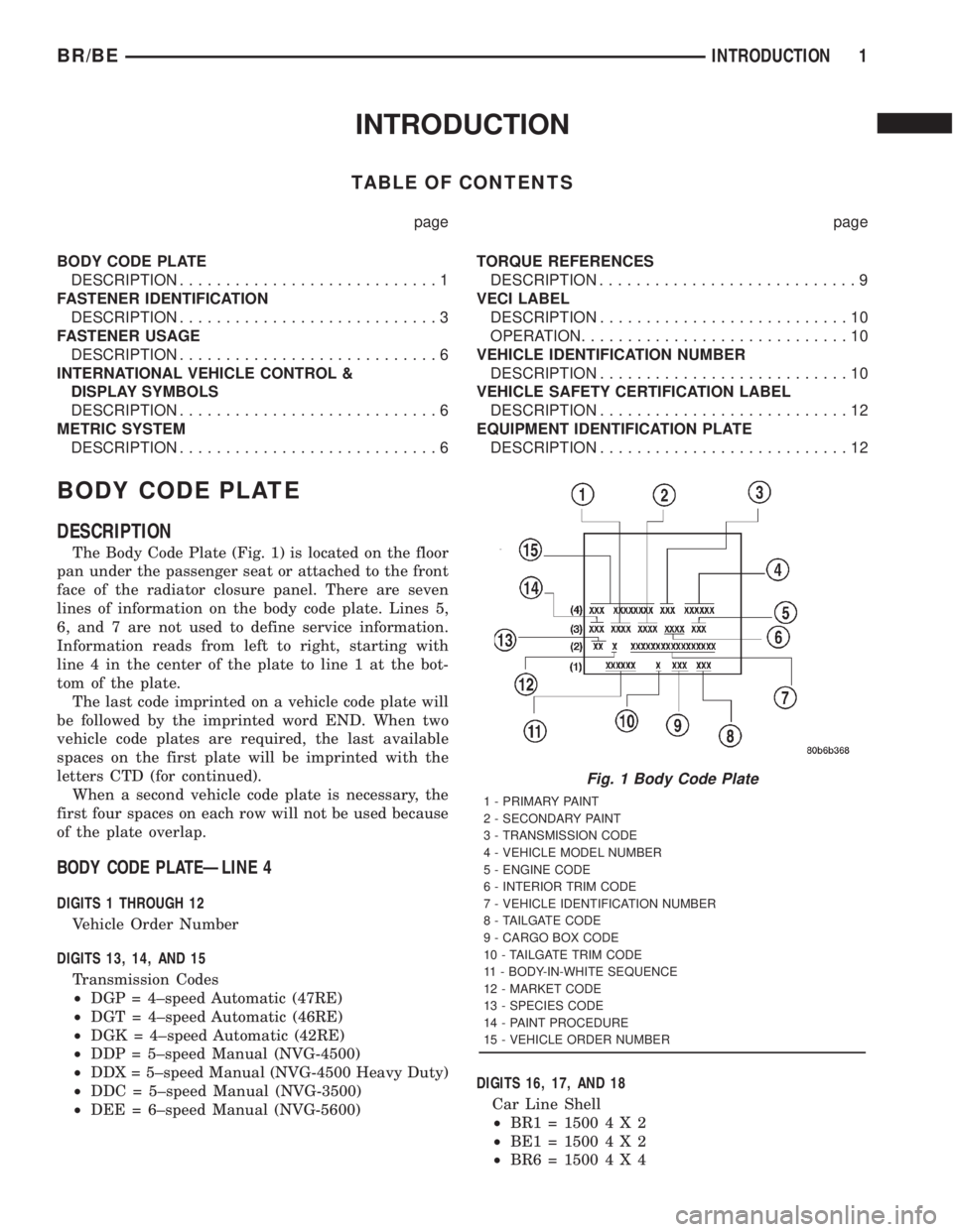
The Body Code Plate (Fig. 1) is located on the floor
pan under the passenger seat or attached to the front
face of the radiator closure panel. There are seven
lines of information on the body code plate. Lines 5,
6, and 7 are not used to define service information.
Information reads from left to right, starting with
line 4 in the center of the plate to line 1 at the bot-
tom of the plate.
The last code imprinted on a vehicle code plate will
be followed by the imprinted word END. When two
vehicle code plates are required, the last available
spaces on the first plate will be imprinted with the
letters CTD (for continued).
When a second vehicle code plate is necessary, the
first four spaces on each row will not be used because
of the plate overlap.
BODY CODE PLATEÐLINE 4
DIGITS 1 THROUGH 12
Vehicle Order Number
DIGITS 13, 14, AND 15
Transmission Codes
²DGP = 4±speed Automatic (47RE)
²DGT = 4±speed Automatic (46RE)
²DGK = 4±speed Automatic (42RE)
²DDP = 5±speed Manual (NVG-4500)
²DDX = 5±speed Manual (NVG-4500 Heavy Duty)
²DDC = 5±speed Manual (NVG-3500)
²DEE = 6±speed Manual (NVG-5600)DIGITS 16, 17, AND 18
Car Line Shell
²BR1=15004X2
²BE1=15004X2
²BR6=15004X4
Fig. 1 Body Code Plate
1 - PRIMARY PAINT
2 - SECONDARY PAINT
3 - TRANSMISSION CODE
4 - VEHICLE MODEL NUMBER
5 - ENGINE CODE
6 - INTERIOR TRIM CODE
7 - VEHICLE IDENTIFICATION NUMBER
8 - TAILGATE CODE
9 - CARGO BOX CODE
10 - TAILGATE TRIM CODE
11 - BODY-IN-WHITE SEQUENCE
12 - MARKET CODE
13 - SPECIES CODE
14 - PAINT PROCEDURE
15 - VEHICLE ORDER NUMBER
BR/BEINTRODUCTION 1
Page 7 of 2889

FASTENER USAGE
DESCRIPTION - FASTENER USAGE
WARNING: USE OF AN INCORRECT FASTENER
MAY RESULT IN COMPONENT DAMAGE OR PER-
SONAL INJURY.
Figure art, specifications and torque references in
this Service Manual are identified in metric and SAE
format.
During any maintenance or repair procedures, it is
important to salvage all fasteners (nuts, bolts, etc.)
for reassembly. If the fastener is not salvageable, a
fastener of equivalent specification must be used.
DESCRIPTION - THREADED HOLE REPAIR
Most stripped threaded holes can be repaired using
a Helicoilt. Follow the manufactures recommenda-
tions for application and repair procedures.
INTERNATIONAL VEHICLE
CONTROL & DISPLAY
SYMBOLS
DESCRIPTION - INTERNATIONAL SYMBOLS
The graphic symbols illustrated in the following
International Control and Display Symbols Chart are
used to identify various instrument controls. The
symbols correspond to the controls and displays that
are located on the instrument panel.
METRIC SYSTEM
DESCRIPTION - METRIC SYSTEM
The metric system is based on quantities of one,
ten, one hundred, one thousand and one million .
The following chart will assist in converting metric
units to equivalent English and SAE units, or vise
versa.
International Symbols
1 High Beam 13 Rear Window Washer
2 Fog Lamps 14 Fuel
3 Headlamp, Parking Lamps, Panel Lamps 15 Engine Coolant Temperature
4 Turn Warning 16 Battery Charging Condition
5 Hazard Warning 17 Engine Oil
6 Windshield Washer 18 Seat Belt
7 Windshield Wiper 19 Brake Failure
8 Windshield Wiper and Washer 20 Parking Brake
9 Windscreen Demisting and Defrosting 21 Front Hood
10 Ventilating Fan 22 Rear hood (Decklid)
11 Rear Window Defogger 23 Horn
12 Rear Window Wiper 24 Lighter
6 INTRODUCTIONBR/BE
Page 339 of 2889
OPERATIONÐCOOLING SYSTEM
The cooling system regulates engine operating tem-
perature. It allows the engine to reach normal oper-
ating temperature as quickly as possible. It also
maintains normal operating temperature and pre-
vents overheating.
The cooling system also provides a means of heat-
ing the passenger compartment and cooling the auto-
matic transmission fluid (if equipped). The cooling
system is pressurized and uses a centrifugal water
pump to circulate coolant throughout the system.
An optional factory installed maximum duty cool-
ing package is available on most models. This pack-
age will provide additional cooling capacity for
vehicles used under extreme conditions such as
trailer towing in high ambient temperatures.
DIAGNOSIS AND TESTING - PRELIMINARY
CHECKS
ENGINE COOLING SYSTEM OVERHEATING
Establish what driving conditions caused the com-
plaint. Abnormal loads on the cooling system such as
the following may be the cause:
²PROLONGED IDLE
²VERY HIGH AMBIENT TEMPERATURE
²SLIGHT TAIL WIND AT IDLE
²SLOW TRAFFIC
²TRAFFIC JAMS
²HIGH SPEED OR STEEP GRADES
Driving techniques that avoid overheating are:
²Idle with A/C off when temperature gauge is at
end of normal range.²Increasing engine speed for more air flow is rec-
ommended.
TRAILER TOWING:
Consult Trailer Towing section of owners manual.
Do not exceed limits.
AIR CONDITIONING; ADD-ON OR AFTER MARKET:
A maximum cooling package should have been
ordered with vehicle if add-on or after market A/C is
installed. If not, maximum cooling system compo-
nents should be installed for model involved per
manufacturer's specifications.
RECENT SERVICE OR ACCIDENT REPAIR:
Determine if any recent service has been per-
formed on vehicle that may effect cooling system.
This may be:
²Engine adjustments (incorrect timing)
²Slipping engine accessory drive belt(s)
²Brakes (possibly dragging)
²Changed parts. Incorrect water pump or pump
rotating in wrong direction due to belt not correctly
routed
²Reconditioned radiator or cooling system refill-
ing (possibly under filled or air trapped in system).
NOTE: If investigation reveals none of the previous
items as a cause for an engine overheating com-
plaint, (Refer to 7 - COOLING - DIAGNOSIS AND
TESTING)
DIAGNOSIS AND TESTINGÐON-BOARD
DIAGNOSTICS (OBD)
COOLING SYSTEM RELATED DIAGNOSTICS
The powertrain control module (PCM) has been
programmed to monitor certain cooling system com-
ponents:
²If the engine has remained cool for too long a
period, such as with a stuck open thermostat, a Diag-
nostic Trouble Code (DTC) can be set.
²If an open or shorted condition has developed in
the relay circuit controlling the electric radiator fan,
a Diagnostic Trouble Code (DTC) can be set.
If the problem is sensed in a monitored circuit
often enough to indicated an actual problem, a DTC
is stored. The DTC will be stored in the PCM mem-
ory for eventual display to the service technician.
(Refer to 25 - EMISSIONS CONTROL - DESCRIP-
TION).
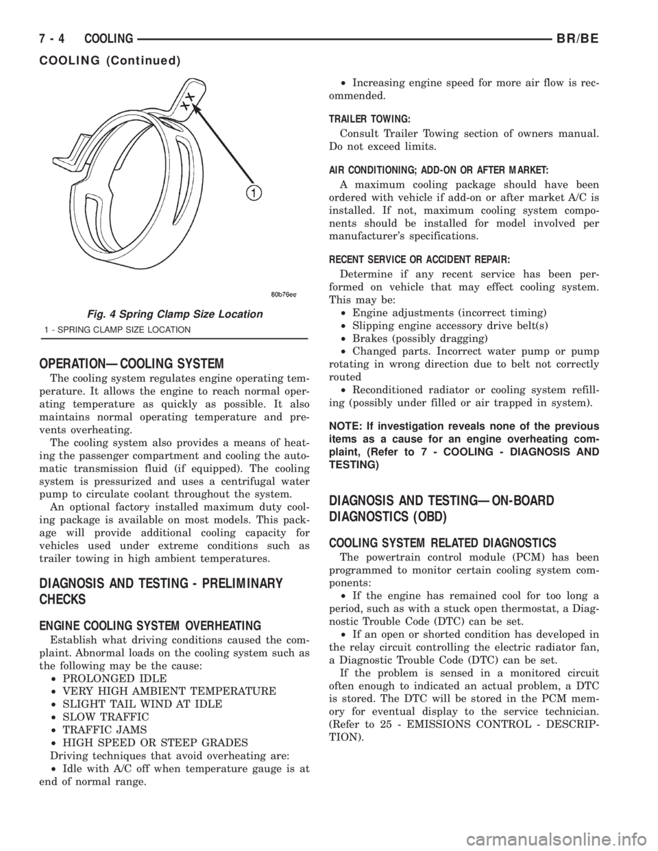
Fig. 4 Spring Clamp Size Location
1 - SPRING CLAMP SIZE LOCATION
7 - 4 COOLINGBR/BE
COOLING (Continued)
Page 368 of 2889
CONDITION POSSIBLE CAUSES CORRECTION
NOISE (Objectional squeal, spueak,
or rumble is heard or felt while drive
belt is in operation)1. Incorrect belt tension 1. Inspect/Replace tensioner if
necessary
2. Bearing noise 2. Locate and repair
3. Belt misalignment 3. Align belt/pulley(s)
4. Belt to pulley mismatch 4. Install correct belt
5. Driven component induced
vibration5. Locate defective driven
component and repair
TENSION SHEETING FABRIC
FAILURE
(Woven fabric on outside,
circumference of belt has cracked or
separated from body of belt)1. Tension sheeting contacting
stationary object1. Correct rubbing condition
2. Excessive heat causing woven
fabric to age2. Replace belt
3. Tension sheeting splice has
fractured3. Replace belt
CORD EDGE FAILURE
(Tensile member exposed at edges
of belt or separated from belt body)1. Incorrect belt tension 1. Inspect/Replace tensioner if
necessary
2. Belt contacting stationary object 2. Replace belt
3. Pulley(s) out of tolerance 3. Replace pulley
4. Insufficient adhesion between
tensile member and rubber matrix4. Replace belt
REMOVAL
CAUTION: Do not attempt to check belt tension with
a belt tension gauge on vehicles equipped with an
automatic belt tensioner. Refer to Automatic Belt
Tensioner in this group.
NOTE: The belt routing schematics are published
from the latest information available at the time of
publication. If anything differs between these sche-
matics and the Belt Routing Label, use the sche-
matics on Belt Routing Label.This label is located in
the engine compartment.
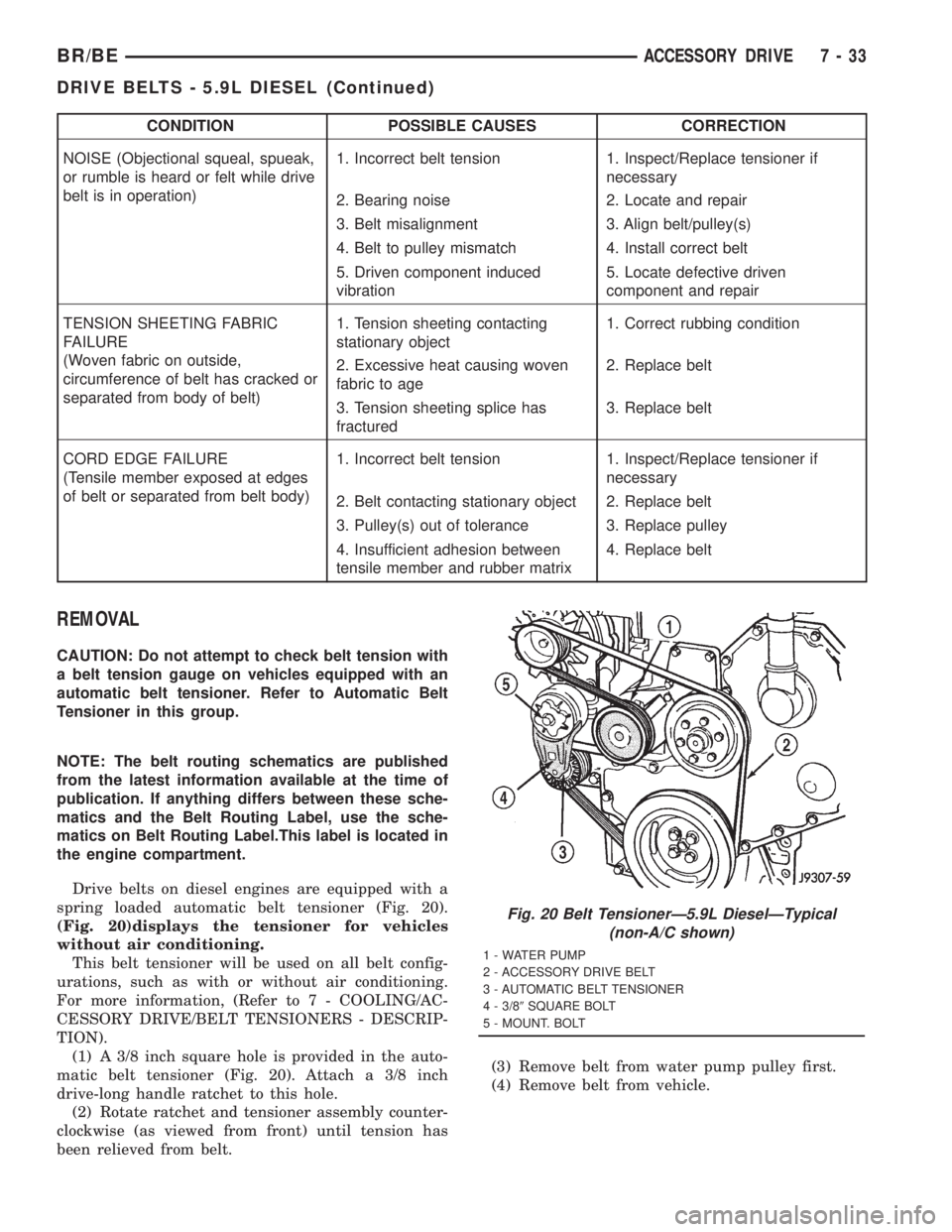
Drive belts on diesel engines are equipped with a
spring loaded automatic belt tensioner (Fig. 20).
(Fig. 20)displays the tensioner for vehicles
without air conditioning.
This belt tensioner will be used on all belt config-
urations, such as with or without air conditioning.
For more information, (Refer to 7 - COOLING/AC-
CESSORY DRIVE/BELT TENSIONERS - DESCRIP-
TION).
(1) A 3/8 inch square hole is provided in the auto-
matic belt tensioner (Fig. 20). Attach a 3/8 inch
drive-long handle ratchet to this hole.
(2) Rotate ratchet and tensioner assembly counter-
clockwise (as viewed from front) until tension has
been relieved from belt.(3) Remove belt from water pump pulley first.
(4) Remove belt from vehicle.
Fig. 20 Belt TensionerÐ5.9L DieselÐTypical
(non-A/C shown)
1 - WATER PUMP
2 - ACCESSORY DRIVE BELT
3 - AUTOMATIC BELT TENSIONER
4 - 3/89SQUARE BOLT
5 - MOUNT. BOLT
BR/BEACCESSORY DRIVE 7 - 33
DRIVE BELTS - 5.9L DIESEL (Continued)
Page 426 of 2889
Audio System Diagnosis
CONDITION POSSIBLE CAUSE CORRECTION
NO AUDIO 1. Fuse faulty. 1. Check radio fuses in junction block. Replace faulty fuses, if
required.
2. Radio connector faulty. 2. Check for loose or corroded radio connections. Repair, if
required.
3. Wiring faulty. 3. Check for battery voltage at radio connector. Repair wiring,
if required.
4. Ground faulty. 4. Check for continuity between radio chassis and a known
good ground. There should be continuity. Repair ground, if
required.
5. Radio faulty. 5. Refer to Radio in the Diagnosis and Testing section of this
group.
6. Speakers faulty. 6. Refer to Speaker in the Diagnosis and Testing section of
this group.
7. Amplifier faulty (if
equipped).7. Refer to Speaker in the Diagnosis and Testing section of
this group.
NO DISPLAY 1. Fuse faulty. 1. Check radio fuses in junction block. Replace faulty fuses, if
required.
2. Radio connector faulty. 2. Check for loose or corroded radio connections. Repair, if
required.
3. Wiring faulty. 3. Check for battery voltage at radio connector. Repair wiring,
if required.
4. Ground faulty. 4. Check for continuity between radio chassis and a known
good ground. There should be continuity. Repair ground, if
required.
5. Radio faulty. 5. Refer to Radio in the Diagnosis and Testing section of this
group.
CLOCK WILL NOT
KEEP SET TIME1. Fuse faulty. 1. Check ignition-off draw fuse. Replace faulty fuse, if
required.
2. Radio connector faulty. 2. Check for loose or corroded radio connections. Repair, if
required.
3. Wiring faulty. 3. Check for battery voltage at radio connector. Repair wiring,
if required.
4. Ground faulty. 4. Check for continuity between radio chassis and a known
good ground. There should be continuity. Repair ground, if
required.
5. Radio faulty. 5. Refer to Radio in the Diagnosis and Testing section of this
group.
POOR RADIO
RECEPTION1. Antenna faulty. 1. Refer to Antenna in the Diagnosis and Testing section of
this group.
2. Ground faulty. 2. Check for continuity between radio chassis and a known
good ground. There should be continuity. Repair ground, if
required.
3. Radio faulty. 3. Refer to Radio in the Diagnosis and Testing section of this
group.
4. Faulty EMI or RFI
noise suppression.4. Refer to Radio Frequency Interference in the Diagnosis
and Testing section of this group.
BR/BEAUDIO 8A - 3
AUDIO (Continued)
Page 433 of 2889
(7) Remove the radio receiver from the instrument
panel. Refer to Audio, Radio for the procedures.
(8) Pull the antenna cable out through the radio
receiver opening in the instrument panel.
(9) Untie the cord or twine from the instrument
panel antenna cable connector, leaving the cord or
twine in place of the cable in the instrument panel.
(10) Remove the antenna cable from the instru-
ment panel.
INSTALLATION
(1) Tie the end of the cord or twine that was used
during instrument panel antenna cable removal
securely to the connector on the end of the antenna
cable being installed into the instrument panel. This
cord will be used to pull or ªfishº the cable back into
position.
(2) Using the cord or twine, pull the antenna cable
through the radio receiver opening from under the
instrument panel.
(3) Install the radio receiver onto the instrument
panel. Refer to Audio, Radio for the procedures.
(4) Reach through the glove box opening to engage
the antenna cable with the retainer clips on the back
of the instrument panel.
(5) Install the glove box onto the instrument panel.
Refer to Body, Instrument Panel for the procedures.
(6) Untie the cord or twine from the instrument
panel antenna cable connector.
(7) Reach under the passenger side of the instru-
ment panel near the right cowl side inner panel to
reconnect the two halves of the radio antenna coaxial
cable connector. Wrap the connection with a piece of
foam tape.
(8) Engage the coaxial cable connector with the
retainer clip located on the bottom of the heater-A/C
housing.
(9) Reconnect the battery negative cable.
RADIO
DESCRIPTION
Available factory-installed radio receivers for this
model include an AM/FM/cassette (RAS sales code),
an AM/FM/cassette/5-band graphic equalizer with CD
changer control feature (RBN sales code), an AM/FM/
CD/3-band graphic equalizer (RBR sales code), or an
AM/FM/CD/cassette/3-band graphic equalizer (RAZ
sales code). The factory-installed RAZ sales code
radio receivers can also communicate on the Chrysler
Collision Detection (CCD) data bus network through
a separate two-way wire harness connector. All facto-
ry-installed receivers are stereo Electronically Tuned
Radios (ETR) and include an electronic digital clock
function.These radio receivers can only be serviced by an
authorized radio repair station. See the latest War-
ranty Policies and Procedures manual for a current
listing of authorized radio repair stations.
All vehicles are equipped with an Ignition-Off
Draw (IOD) fuse that is removed when the vehicle is
shipped from the factory. This fuse feeds various
accessories that require battery current when the
ignition switch is in the Off position, including the
clock. The IOD fuse is removed to prevent battery
discharge during vehicle storage.
When removing or installing the IOD fuse, it is
important that the ignition switch be in the Off posi-
tion. Failure to place the ignition switch in the Off
position can cause the radio display to become scram-
bled when the IOD fuse is removed and replaced.
Removing and replacing the IOD fuse again, with the
ignition switch in the Off position, will correct the
scrambled display condition.
The IOD fuse should be checked if the radio or
clock displays are inoperative. The IOD fuse is
located in the junction block. Refer to the fuse layout
label on the back of the instrument panel fuse access
panel for IOD fuse identification and location.
OPERATION
The radio receiver operates on fused battery cur-
rent that is available only when the ignition switch is
in the On or Accessory positions. The electronic digi-
tal clock function of the radio operates on fused bat-
tery current supplied through the IOD fuse,
regardless of the ignition switch position.
For more information on the features, setting pro-
cedures, and control functions for each of the avail-
able factory-installed radio receivers, see the owner's
manual in the vehicle glove box. For complete circuit
diagrams, refer to the appropriate wiring informa-
tion. The wiring information includes wiring dia-
grams, proper wire and connector repair procedures,
details of wire harness routing and retention, connec-
tor pin-out information and location views for the
various wire harness connectors, splices and grounds.
DIAGNOSIS AND TESTING
DIAGNOSIS AND TESTING - RADIO
If the vehicle is equipped with the optional remote
radio switches located on the steering wheel and the
problem being diagnosed is related to one of the
symptoms listed below, be certain to check the
remote radio switches and circuits. Refer to Audio,
Remote Radio Switch prior to attempting radio diag-
nosis or repair.
²Stations changing with no remote radio switch
input
8A - 10 AUDIOBR/BE
INSTRUMENT PANEL ANTENNA CABLE (Continued)
Page 447 of 2889
²Head/Park Lights-On Warning- The CTM
chime tone generator will generate repetitive chime
tones at a fast rate to announce that hard wired
inputs from the driver door ajar switch, headlamp
switch, and ignition switch indicate that the exterior
lamps are turned On with the driver side front door
opened and the ignition switch in the Off position.
The chimes will continue to sound until the exterior
lamps are turned Off, the driver side front door is
closed, or the ignition switch is turned to the On
position, whichever occurs first.
²Key-In-Ignition Warning- The BCM chime
tone generator will generate repetitive chime tones at
a fast rate to announce that hard wired inputs from
the driver door ajar switch, headlamp switch, and
ignition switch indicate that the key is in the ignition
lock cylinder with the driver side front door opened
and the ignition switch in the Off position. The
chimes will continue to sound until the key is
removed from the ignition lock cylinder, the driver
side front door is closed, or the ignition switch is
turned to the On position, whichever occurs first.
²Warning Chime Support- The CTM chime
tone generator will generate repetitive chime tones at
a slow rate to announce that a hard wired chime
request input has been received from the EMIC.
These chime tones provide an audible alert to the
vehicle operator that supplements certain visual indi-
cations displayed by the EMIC. Supplemented indica-
tions include the following:
²The ªAirbagº indicator is illuminated. The
chimes will continue to sound for a duration of about
four seconds each time the indicator is illuminated or
until the ignition switch is turned to the Off position,
whichever occurs first.
²The ªCheck Gagesº indicator is illuminated. The
chimes will continue to sound for a duration of about
two seconds each time the indicator is illuminated or
until the ignition switch is turned to the Off position,
whichever occurs first.
²The ªLow Fuelº indicator is illuminated. The
chimes will continue to sound for a duration of about
two seconds each time the indicator is illuminated or
until the ignition switch is turned to the Off position,
whichever occurs first.
²The ªLow Washº indicator is illuminated. The
chimes will continue to sound for a duration of about
two seconds each time the indicator is illuminated or
until the ignition switch is turned to the Off position,
whichever occurs first.
²The ªTrans Tempº indicator is illuminated (auto-
matic transmission only). The chimes will continue to
sound for a duration of about two seconds each time
the indicator is illuminated or until the ignition
switch is turned to the Off position, whichever occurs
first.²The vehicle is over a programmed speed value
(Middle East Gulf Coast Country (GCC) only). The
CTM chime tone generator will generate repetitive
chime tones at a slow rate to announce that the vehi-
cle speed exceeds a programmed value. The chimes
will continue to sound until the vehicle speed is
below the programmed value.
²The ªWater-In-Fuelº indicator is illuminated
(diesel engine only). The chimes will continue to
sound for a duration of about two seconds each time
the indicator is illuminated or until the ignition
switch is turned to the Off position, whichever occurs
first.
The CTM provides chime service for all available
features in the chime warning system. The CTM
relies upon hard wired inputs from the driver door
ajar switch, the EMIC, the headlamp switch, and the
key-in ignition switch (ignition switch) to provide
chime service for all of the chime warning system
features. Upon receiving the proper inputs, the CTM
activates the integral chime tone generator to pro-
vide the audible chime tone to the vehicle operator.
The chime tone generator in the CTM is capable of
producing repeated chime tones at two different
rates, slow or fast. The slow chime rate is about fifty
chime tones per minute, while the fast chime rate is
about 180 chime tones per minute. The internal pro-
gramming of the CTM and the EMIC determines the
priority of each chime tone request input that is
received, as well as the rate and duration of each
chime tone that is to be generated.
The hard wired chime warning system inputs to
the CTM and the EMIC, as well as other hard wired
circuits for this system may be diagnosed and tested
using conventional diagnostic tools and procedures.
See the owner's manual in the vehicle glove box for
more information on the features provided by the
chime warning system.
DIAGNOSIS AND TESTING - CHIME WARNING
SYSTEM
Refer to the appropriate wiring information. The
wiring information includes wiring diagrams, proper
wire and connector repair procedures, further details
on wire harness routing and retention, as well as
pin-out and location views for the various wire har-
ness connectors, splices and grounds. The hard wired
chime warning system inputs to the Central Timer
Module (CTM) and the Electro-Mechanical Instru-
ment Cluster (EMIC), as well as other hard wired
circuits for this system may be diagnosed and tested
using conventional diagnostic tools and procedures.
8B - 2 CHIME/BUZZERBR/BE
CHIME WARNING SYSTEM (Continued)
Page 459 of 2889
Once a message is broadcast over the CCD data
bus, all electronic control modules on the data bus
have the ability to receive it through their CCD chip.
Reception of CCD messages is also carried out by the
transceiver in the CCD chip. The transceiver moni-
tors the voltage on the data bus for any fluctuations.
When data bus voltage fluctuations are detected,
they are interpreted by the transceiver as binary
messages and sent to the electronic control module's
microprocessor.
BUS BIAS AND TERMINATION
The voltage network used by the CCD data bus to
transmit messages requires both bias and termina-
tion. At least one electronic control module on the
data bus must provide a voltage source for the CCD
data bus network known as bus bias, and there must
be at least one bus termination point for the data bus
circuit to be complete. However, while bias and ter-
mination are both required for data bus operation,
they both do not have to be within the same elec-
tronic control module. The CCD data bus is biased to
approximately 2.5 volts. With each of the electronic
control modules wired in parallel to the data bus, all
modules utilize the same bus bias. Therefore, based
upon vehicle options, the data bus can accommodate
two or twenty electronic control modules without
affecting bus voltage.
The power supplied to the data bus is known as
bus biasing. Bus bias is provided through a series cir-
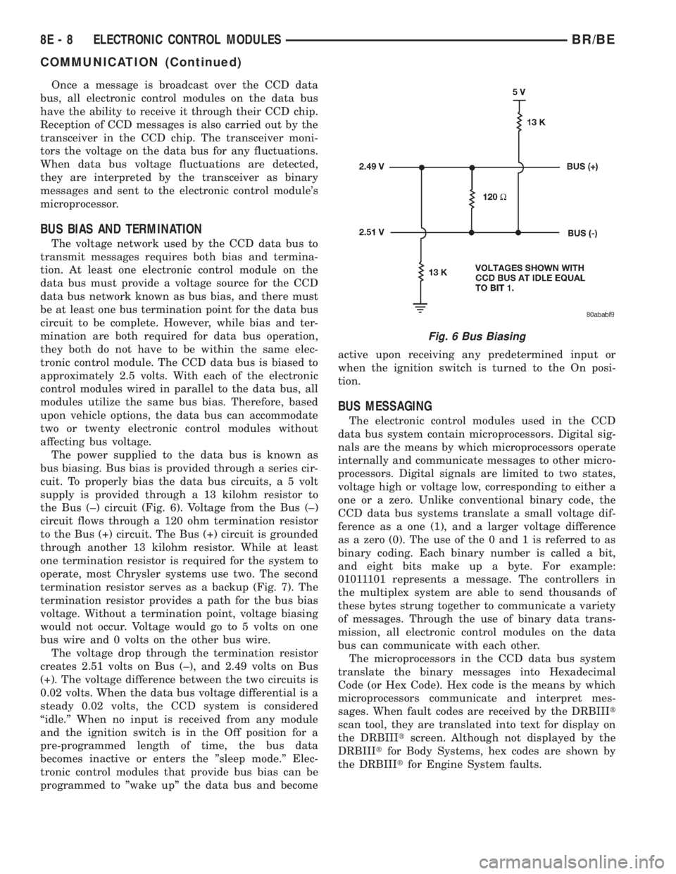
cuit. To properly bias the data bus circuits, a 5 volt
supply is provided through a 13 kilohm resistor to
the Bus (±) circuit (Fig. 6). Voltage from the Bus (±)
circuit flows through a 120 ohm termination resistor
to the Bus (+) circuit. The Bus (+) circuit is grounded
through another 13 kilohm resistor. While at least
one termination resistor is required for the system to
operate, most Chrysler systems use two. The second
termination resistor serves as a backup (Fig. 7). The
termination resistor provides a path for the bus bias
voltage. Without a termination point, voltage biasing
would not occur. Voltage would go to 5 volts on one
bus wire and 0 volts on the other bus wire.
The voltage drop through the termination resistor
creates 2.51 volts on Bus (±), and 2.49 volts on Bus
(+). The voltage difference between the two circuits is
0.02 volts. When the data bus voltage differential is a
steady 0.02 volts, the CCD system is considered
ªidle.º When no input is received from any module
and the ignition switch is in the Off position for a
pre-programmed length of time, the bus data
becomes inactive or enters the ºsleep mode.º Elec-
tronic control modules that provide bus bias can be
programmed to ºwake upº the data bus and becomeactive upon receiving any predetermined input or
when the ignition switch is turned to the On posi-
tion.
BUS MESSAGING
The electronic control modules used in the CCD
data bus system contain microprocessors. Digital sig-
nals are the means by which microprocessors operate
internally and communicate messages to other micro-
processors. Digital signals are limited to two states,
voltage high or voltage low, corresponding to either a
one or a zero. Unlike conventional binary code, the
CCD data bus systems translate a small voltage dif-
ference as a one (1), and a larger voltage difference
as a zero (0). The use of the 0 and 1 is referred to as
binary coding. Each binary number is called a bit,
and eight bits make up a byte. For example:
01011101 represents a message. The controllers in
the multiplex system are able to send thousands of
these bytes strung together to communicate a variety
of messages. Through the use of binary data trans-
mission, all electronic control modules on the data
bus can communicate with each other.
The microprocessors in the CCD data bus system
translate the binary messages into Hexadecimal
Code (or Hex Code). Hex code is the means by which
microprocessors communicate and interpret mes-
sages. When fault codes are received by the DRBIIIt
scan tool, they are translated into text for display on
the DRBIIItscreen. Although not displayed by the
DRBIIItfor Body Systems, hex codes are shown by
the DRBIIItfor Engine System faults.
Fig. 6 Bus Biasing
8E - 8 ELECTRONIC CONTROL MODULESBR/BE
COMMUNICATION (Continued)