2001 DODGE RAM reset
[x] Cancel search: resetPage 48 of 2889
CORRECTED CASTER CHART-CAB CHASSIS
Caster
Correlation
Value
(inches)4x2 8800
lb. GVW
134.7 in.
wheel
base4x4 8800
lb. GVW
4x2 & 4x4
11000 lb.
GVW
134.7 &
138.7 in.
wheel
base4x2 & 4x4
11000 lb.
GVW 162.7
in. wheel
base
Caster61
deg.Caster61
deg.Caster61
deg.
þ5.00 4.27É 3.77É 3.81É
þ4.75 4.39É 3.89É 3.91É
þ4.50 4.51É 4.01É 4.01É
þ4.25 4.64É 4.14É 4.11É
þ4.00 4.76É 4.26É 4.21É
þ3.75 4.88É 4.38É 4.31É
þ3.50 5.00É 4.50É 4.41É
þ3.25 5.12É 4.62É 4.51É
þ3.00 5.25É 4.75É 4.61É
þ2.75 5.37É 4.87É 4.71É
þ2.50 5.49É 4.99É 4.81É
þ2.25 5.61É 5.11É 4.91É
þ2.00 5.74É 5.24É 5.01É
þ1.75 5.86É 5.36É 5.11É
þ1.50 5.98É 5.48É 5.21É
þ1.25 6.10É 5.60É 5.31É
þ1.00 6.23É 5.73É 5.41É
þ0.75 6.33É 5.83É 5.51É
þ0.50 6.47É 5.97É 5.61É
þ0.25 6.59É 6.09É 5.71É
0.00 6.71É 6.21É 5.81É
STANDARD PROCEDURES - ALIGNMENT
LINK/COIL SUSPENSION
Before each alignment reading the vehicle should
be jounced (rear first, then front). Grasp each
bumper at the center and jounce the vehicle up and
down several times. Always release the bumper in
the down position.Set the front end alignment to
specifications while the vehicle is in its NOR-
MALLY LOADED CONDITION.
CAMBER:The wheel camber angle is preset and
is not adjustable.
CASTER:Check the caster of the front axle for
correct angle. Be sure the axle is not bent or twisted.Road test the vehicle and make left and right turn.
Observe the steering wheel return-to-center position.
Low caster will cause poor steering wheel returnabil-
ity.
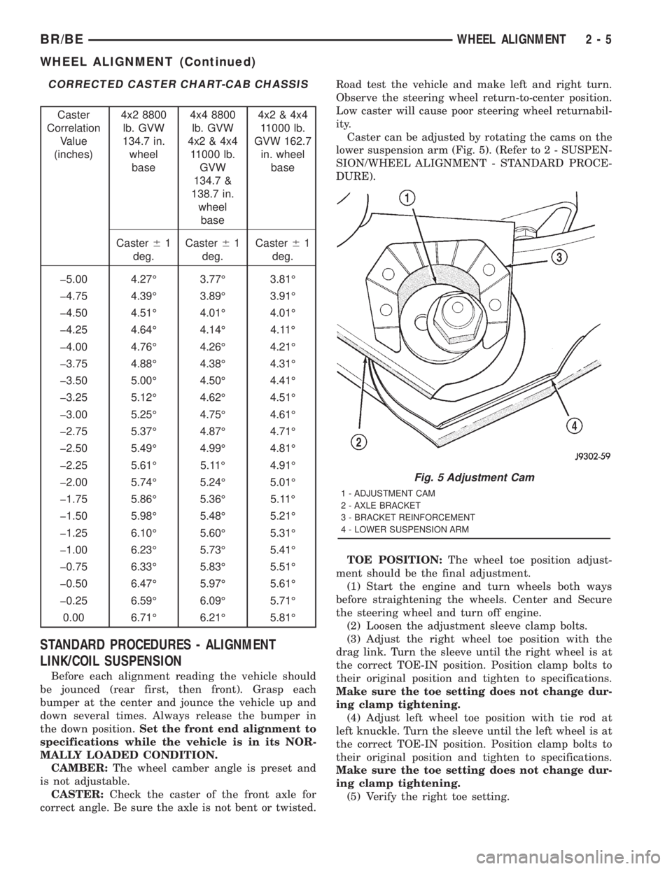
Caster can be adjusted by rotating the cams on the
lower suspension arm (Fig. 5). (Refer to 2 - SUSPEN-
SION/WHEEL ALIGNMENT - STANDARD PROCE-
DURE).
TOE POSITION:The wheel toe position adjust-
ment should be the final adjustment.
(1) Start the engine and turn wheels both ways
before straightening the wheels. Center and Secure
the steering wheel and turn off engine.
(2) Loosen the adjustment sleeve clamp bolts.
(3) Adjust the right wheel toe position with the
drag link. Turn the sleeve until the right wheel is at
the correct TOE-IN position. Position clamp bolts to
their original position and tighten to specifications.
Make sure the toe setting does not change dur-
ing clamp tightening.
(4) Adjust left wheel toe position with tie rod at
left knuckle. Turn the sleeve until the left wheel is at
the correct TOE-IN position. Position clamp bolts to
their original position and tighten to specifications.
Make sure the toe setting does not change dur-
ing clamp tightening.
(5) Verify the right toe setting.
Fig. 5 Adjustment Cam
1 - ADJUSTMENT CAM
2 - AXLE BRACKET
3 - BRACKET REINFORCEMENT
4 - LOWER SUSPENSION ARM
BR/BEWHEEL ALIGNMENT 2 - 5
WHEEL ALIGNMENT (Continued)
Page 328 of 2889
REMOVAL
(1) Remove transmission and transfer case, if
equipped. Refer to Group 21, Transmission and
Transfer Case, for proper procedures.
(2) Remove clutch housing, for NV4500 equipped
vehicles.
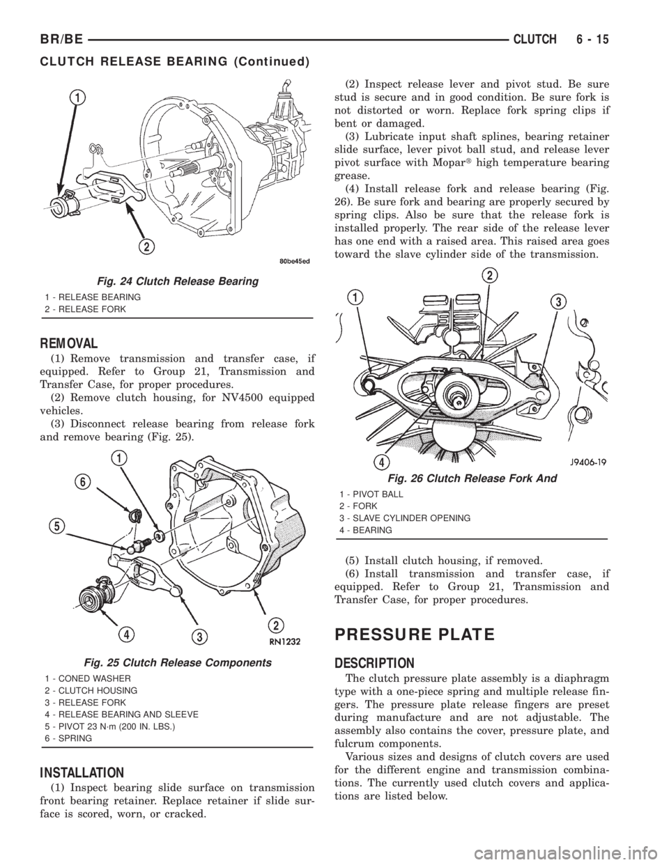
(3) Disconnect release bearing from release fork
and remove bearing (Fig. 25).
INSTALLATION
(1) Inspect bearing slide surface on transmission
front bearing retainer. Replace retainer if slide sur-
face is scored, worn, or cracked.(2) Inspect release lever and pivot stud. Be sure
stud is secure and in good condition. Be sure fork is
not distorted or worn. Replace fork spring clips if
bent or damaged.
(3) Lubricate input shaft splines, bearing retainer
slide surface, lever pivot ball stud, and release lever
pivot surface with Moparthigh temperature bearing
grease.
(4) Install release fork and release bearing (Fig.
26). Be sure fork and bearing are properly secured by
spring clips. Also be sure that the release fork is
installed properly. The rear side of the release lever
has one end with a raised area. This raised area goes
toward the slave cylinder side of the transmission.
(5) Install clutch housing, if removed.
(6) Install transmission and transfer case, if
equipped. Refer to Group 21, Transmission and
Transfer Case, for proper procedures.
PRESSURE PLATE
DESCRIPTION
The clutch pressure plate assembly is a diaphragm
type with a one-piece spring and multiple release fin-
gers. The pressure plate release fingers are preset
during manufacture and are not adjustable. The
assembly also contains the cover, pressure plate, and
fulcrum components.
Various sizes and designs of clutch covers are used
for the different engine and transmission combina-
tions. The currently used clutch covers and applica-
tions are listed below.
Fig. 24 Clutch Release Bearing
1 - RELEASE BEARING
2 - RELEASE FORK
Fig. 25 Clutch Release Components
1 - CONED WASHER
2 - CLUTCH HOUSING
3 - RELEASE FORK
4 - RELEASE BEARING AND SLEEVE
5 - PIVOT 23 N´m (200 IN. LBS.)
6 - SPRING
Fig. 26 Clutch Release Fork And
1 - PIVOT BALL
2 - FORK
3 - SLAVE CYLINDER OPENING
4 - BEARING
BR/BECLUTCH 6 - 15
CLUTCH RELEASE BEARING (Continued)
Page 434 of 2889
²Radio memory presets not working properly
²Volume changes with no remote radio switch
input
²Remote radio switch buttons taking on other
functions
²CD player skipping tracks
²Remote radio switch inoperative.
For complete circuit diagrams, refer to the appro-
priate wiring information. The wiring information
includes wiring diagrams, proper wire and connector
repair procedures, details of wire harness routing
and retention, connector pin-out information and
location views for the various wire harness connec-
tors, splices and grounds.
WARNING: ON VEHICLES EQUIPPED WITH AIR-
BAGS, REFER TO ELECTRICAL, RESTRAINTS
BEFORE ATTEMPTING ANY STEERING WHEEL,
STEERING COLUMN, OR INSTRUMENT PANEL
COMPONENT DIAGNOSIS OR SERVICE. FAILURE
TO TAKE THE PROPER PRECAUTIONS COULD
RESULT IN ACCIDENTAL AIRBAG DEPLOYMENT
AND POSSIBLE PERSONAL INJURY.
CAUTION: The speaker output of the radio receiver
is a ªfloating groundº system. Do not allow any
speaker lead to short to ground, as damage to the
radio receiver may result.
(1) Check the fused B(+) fuse in the junction block.
If OK, go to Step 2. If not OK, repair the shorted cir-
cuit or component as required and replace the faulty
fuse.
(2) Check for battery voltage at the fused B(+) fuse
in the junction block. If OK, go to Step 3. If not OK,
repair the open fused B(+) circuit to the Power Dis-
tribution Center (PDC) as required.
(3) Check the fused ignition switch output (acc/
run) fuse in the junction block. If OK, go to Step 4. If
not OK, repair the shorted circuit or component as
required and replace the faulty fuse(s).
(4) Turn the ignition switch to the On position.
Check for battery voltage at the fused ignition switch
output (acc/run) fuse in the junction block. If OK, go
to Step 5. If not OK, repair the open fused ignition
switch output (acc/run) circuit to the ignition switch
as required.
(5) Turn the ignition switch to the Off position.
Disconnect and isolate the battery negative cable.
Remove the radio receiver from the instrument
panel, but do not disconnect the wire harness connec-
tors. Check for continuity between the radio receiver
chassis and a good ground. There should be continu-
ity. If OK, go to Step 6. If not OK, repair the open
ground circuit to ground as required.(6) Connect the battery negative cable. Turn the
ignition switch to the On position. Check for battery
voltage at the fused ignition switch output (acc/run)
circuit cavity of the left (gray) radio wire harness
connector. If OK, go to Step 7. If not OK, repair the
open fused ignition switch output (acc/run) circuit to
the junction block fuse as required.
(7) Turn the ignition switch to the Off position.
Check for battery voltage at the fused B(+) circuit
cavity of the left (gray) radio wire harness connector.
If OK, replace the faulty radio receiver. If not OK,
repair the open fused B(+) circuit to the junction
block fuse as required.
REMOVAL
(1) Disconnect and isolate the battery negative
cable.
(2) Remove the cluster bezel from the instrument
panel.
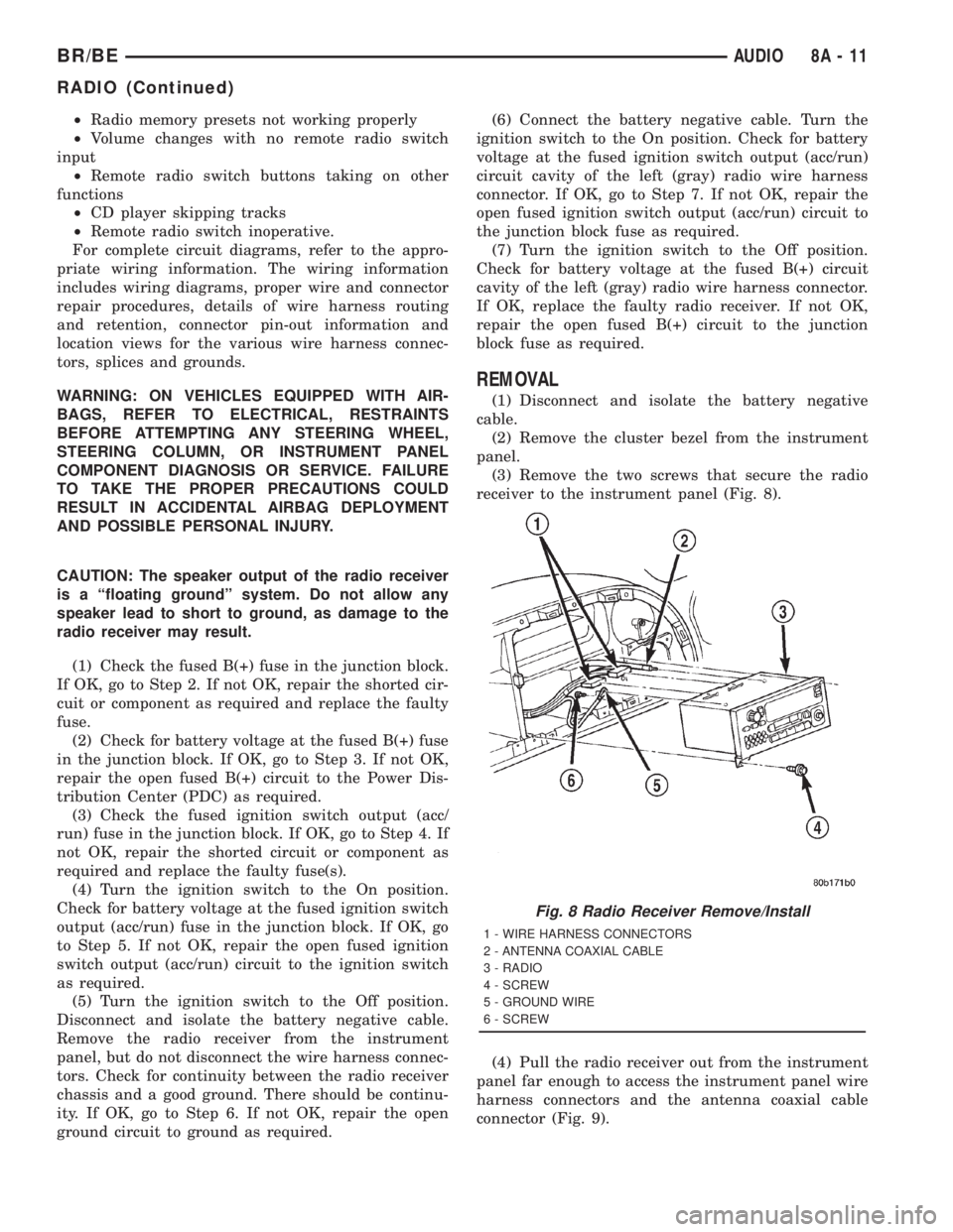
(3) Remove the two screws that secure the radio
receiver to the instrument panel (Fig. 8).
(4) Pull the radio receiver out from the instrument
panel far enough to access the instrument panel wire
harness connectors and the antenna coaxial cable
connector (Fig. 9).
Fig. 8 Radio Receiver Remove/Install
1 - WIRE HARNESS CONNECTORS
2 - ANTENNA COAXIAL CABLE
3 - RADIO
4 - SCREW
5 - GROUND WIRE
6 - SCREW
BR/BEAUDIO 8A - 11
RADIO (Continued)
Page 438 of 2889
(6) Remove the heater core ground strap from the
top of the heater-A/C housing.
INSTALLATION
(1) Position the heater core ground strap and the
heater core tube retaining strap to the top of the
heater-A/C housing.
(2) Install and tighten the screw that secures the
heater core ground strap eyelet and the heater core
tube retaining strap to the top of the heater-A/C
housing. Tighten the screw to 2.2 N´m (20 in. lbs.).
(3) Position the heater core ground strap eyelet
over the stud on the dash panel.
(4) Install and tighten the nut that secures the
heater core ground strap eyelet to the stud on the
dash panel. Tighten the nut to 3.9 N´m (35 in. lbs.).
(5) Install the glove box onto the instrument panel.
Refer to Body, Instrument Panel for the procedures.
(6) Reconnect the battery negative cable.
REMOTE SWITCHES
DESCRIPTION
A remote radio switch option is available on models
equipped with the AM/FM/CD/cassette/3-band
graphic equalizer (RAZ sales code) radio receiver and
the high-line Central Timer Module (CTM). Refer to
Electrical, Body Control/Central Timer Module for
more information on this component.
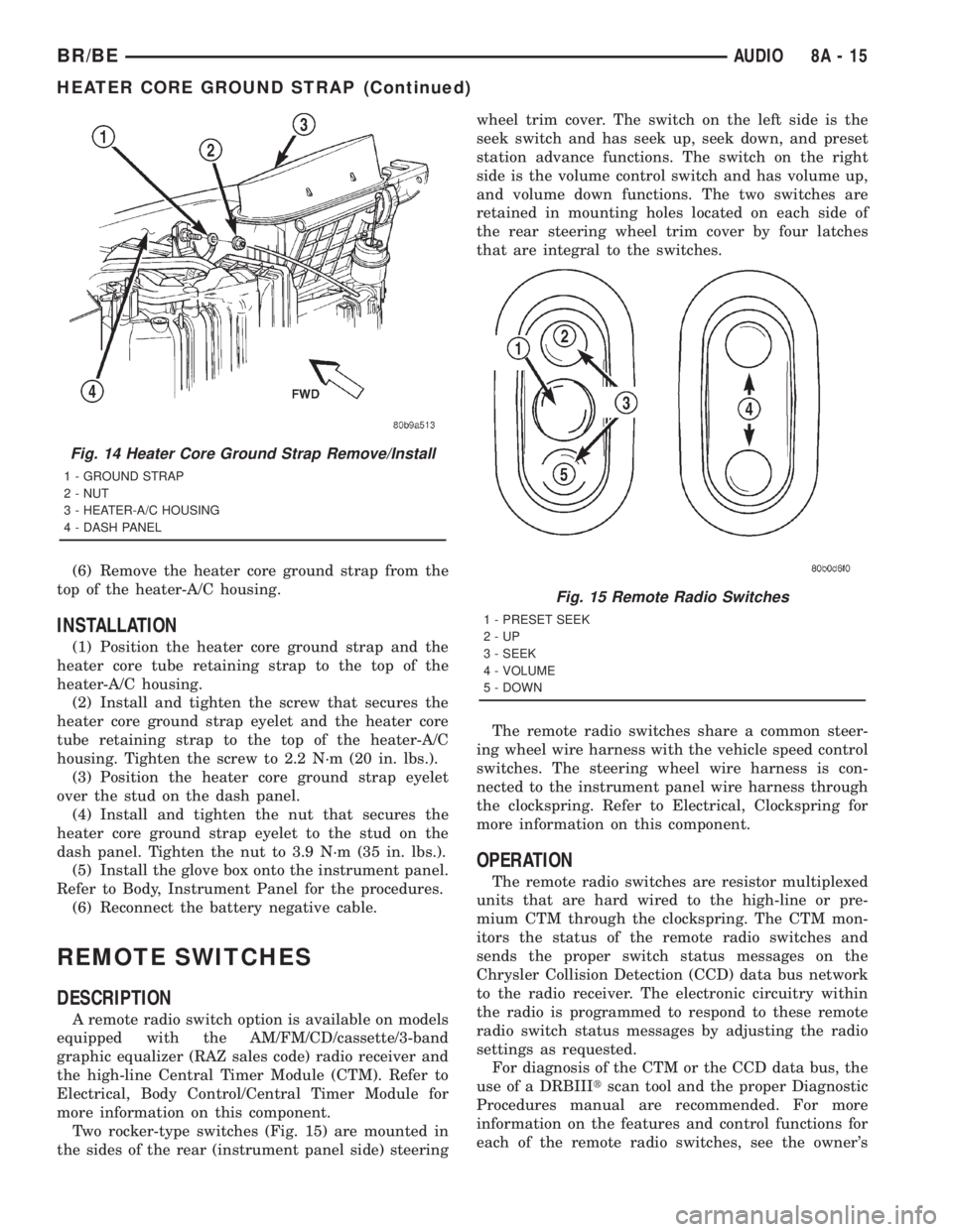
Two rocker-type switches (Fig. 15) are mounted in
the sides of the rear (instrument panel side) steeringwheel trim cover. The switch on the left side is the
seek switch and has seek up, seek down, and preset
station advance functions. The switch on the right
side is the volume control switch and has volume up,
and volume down functions. The two switches are
retained in mounting holes located on each side of
the rear steering wheel trim cover by four latches
that are integral to the switches.
The remote radio switches share a common steer-
ing wheel wire harness with the vehicle speed control
switches. The steering wheel wire harness is con-
nected to the instrument panel wire harness through
the clockspring. Refer to Electrical, Clockspring for
more information on this component.
OPERATION
The remote radio switches are resistor multiplexed
units that are hard wired to the high-line or pre-
mium CTM through the clockspring. The CTM mon-
itors the status of the remote radio switches and
sends the proper switch status messages on the
Chrysler Collision Detection (CCD) data bus network
to the radio receiver. The electronic circuitry within
the radio is programmed to respond to these remote
radio switch status messages by adjusting the radio
settings as requested.
For diagnosis of the CTM or the CCD data bus, the
use of a DRBIIItscan tool and the proper Diagnostic
Procedures manual are recommended. For more
information on the features and control functions for
each of the remote radio switches, see the owner's
Fig. 14 Heater Core Ground Strap Remove/Install
1 - GROUND STRAP
2 - NUT
3 - HEATER-A/C HOUSING
4 - DASH PANEL
Fig. 15 Remote Radio Switches
1 - PRESET SEEK
2-UP
3 - SEEK
4 - VOLUME
5 - DOWN
BR/BEAUDIO 8A - 15
HEATER CORE GROUND STRAP (Continued)
Page 455 of 2889
²Horn relay control - high-line/premium version
only
²VTSS indicator driver - high-line/premium ver-
sion only
²Wiper motor relay control
MESSAGING
The high-line/premium CTM uses the following
messages received from other electronic modules over
the CCD data bus:
²Airbag Deploy (ACM)
²Charging System Failure (PCM)
²Engine RPM (PCM)
²System Voltage (PCM)
²Vehicle Speed (PCM)
²Voltage Fault (PCM)
The high-line/premium CTM provides the following
messages to other electronic modules over the CCD
data bus:
²Engine Enable (PCM)
²Radio Seek Up (Radio)
²Radio Seek Down (Radio)
²Radio Volume Up (Radio)
²Radio Volume Down (Radio)
²Preset Scan (Radio)
DIAGNOSIS AND TESTING - CENTRAL TIMER
MODULE
The hard wired inputs to and outputs from the
Central Timer Module (CTM) may be diagnosed and
tested using conventional diagnostic tools and meth-
ods. Refer to the appropriate wiring information. The
wiring information includes wiring diagrams, proper
wire and connector repair procedures, further details
on wire harness routing and retention, as well as
pin-out and location views for the various wire har-
ness connectors, splices and grounds.
However, conventional diagnostic methods may not
prove conclusive in the diagnosis of the high-line/pre-
mium CTM. In order to obtain conclusive testing of
the high-line/premium CTM, the Chrysler Collision
Detection (CCD) data bus network and all of the elec-
tronic modules that provide inputs to or receive out-
puts from the CTM must also be checked. The most
reliable, efficient, and accurate means to diagnose
the high-line/premium CTM, the CCD data bus net-
work, and the electronic modules that provide inputs
to or receive outputs from the high-line/premium
CTM requires the use of a DRBIIItscan tool and the
appropriate diagnostic information. The DRBIIIt
scan tool can provide confirmation that the CCD data
bus network is functional, that all of the electronic
modules are sending and receiving the proper mes-
sages over the CCD data bus, and that the CTM is
receiving the proper hard wired inputs and respond-ing with the proper hard wired outputs needed to
perform its many functions.
WARNING: ON VEHICLES EQUIPPED WITH AIR-
BAGS, DISABLE THE AIRBAG SYSTEM BEFORE
ATTEMPTING ANY STEERING WHEEL, STEERING
COLUMN, OR INSTRUMENT PANEL COMPONENT
DIAGNOSIS OR SERVICE. DISCONNECT AND ISO-
LATE THE BATTERY NEGATIVE (GROUND) CABLE,
THEN WAIT TWO MINUTES FOR THE AIRBAG SYS-
TEM CAPACITOR TO DISCHARGE BEFORE PER-
FORMING FURTHER DIAGNOSIS OR SERVICE. THIS
IS THE ONLY SURE WAY TO DISABLE THE AIRBAG
SYSTEM. FAILURE TO TAKE THE PROPER PRE-
CAUTIONS COULD RESULT IN ACCIDENTAL AIR-
BAG DEPLOYMENT AND POSSIBLE PERSONAL
INJURY.
NOTE: The following tests may not prove conclu-
sive in the diagnosis of the high-line or premium
versions of the Central Timer Module (CTM). The
most reliable, efficient, and accurate means to diag-
nose the high-line or premium CTM requires the
use of a DRBIIITscan tool and the appropriate diag-
nostic information.
(1) Check the fused B(+) fuse (Fuse 13 - 10
ampere) in the Junction Block (JB). If OK, go to Step
2. If not OK, repair the shorted circuit or component
as required and replace the faulty fuse.
(2) Check for battery voltage at the fused B(+) fuse
(Fuse 13 - 10 ampere) in the JB. If OK, go to Step 3.
If not OK, repair the open fused B(+) circuit between
the JB and the Power Distribution Center (PDC) as
required.
(3) For a base version CTM, check the fused igni-
tion switch output (st-run) fuse (Fuse 11 - 10 ampere)
in the JB. For a high-line/premium version CTM,
check the fused ignition switch output (run-acc) fuse
(Fuse6-25ampere) in the JB. If OK, go to Step 4. If
not OK, repair the shorted circuit or component as
required and replace the faulty fuse.
(4) Turn the ignition switch to the On position. For
a base version CTM, check for battery voltage at the
fused ignition switch output (st-run) fuse (Fuse 11 -
10 ampere) in the JB. For a high-line/premium ver-
sion CTM, check for battery voltage at the fused igni-
tion switch output (run-acc) fuse (Fuse6-25
ampere) in the JB. If OK, go to Step 5. If not OK,
repair the shorted circuit or component as required
and replace the faulty fuse.
(5) Turn the ignition switch to the Off position.
Disconnect and isolate the battery negative cable.
Remove the CTM from its mounting bracket to access
the CTM wire harness connector(s). Disconnect the
instrument panel wire harness connector(s) for the
8E - 4 ELECTRONIC CONTROL MODULESBR/BE
BODY CONTROL/CENTRAL TIMER MODULE (Continued)
Page 462 of 2889

the module attempts to have the CCD chip re-send
the message.
DIAGNOSIS AND TESTING - CCD DATA BUS
CCD BUS FAILURE
The CCD data bus can be monitored using the
DRBIIItscan tool. However, it is possible for the
data bus to pass all tests since the voltage parame-
ters will be in ªrangeª and false signals are being
sent. There are essentially 12 ªhard failuresª that
can occur with the CCD data bus:
²Bus Shorted to Battery
²Bus Shorted to 5 Volts
²Bus Shorted to Ground
²Bus (+) Shorted to Bus (±)
²Bus (±) and Bus (+) Open
²Bus (+) Open
²Bus (±) Open
²No Bus Bias
²Bus Bias Level Too High
²Bus Bias Level Too Low
²No Bus Termination
²Not Receiving Bus Messages Correctly
Refer to the appropriate diagnostic procedures for
details on how to diagnose these faults using a
DRBIIItscan tool.
BUS FAILURE VISUAL SYMPTOM DIAGNOSIS
The following visible symptoms or customer com-
plaints, alone or in combination, may indicate a CCD
data bus failure:
²Airbag Indicator Lamp and Malfuntion Indicator
Lamp (MIL) Illuminated
²Instrument Cluster Gauges (All) Inoperative
²No Compass Mini-Trip Computer (CMTC) Oper-
ation
CONTROLLER ANTILOCK
BRAKE
DESCRIPTION
The Controller Antilock Brakes (CAB) is a micro-
processor which handles testing, monitoring and con-
trolling the ABS brake system operation (Fig. 10).
The CAB functions are:
²Perform self-test diagnostics.
²Monitor the RWAL brake system for proper oper-
ation.
²Control the RWAL valve solenoids.
NOTE: If the CAB needs to be replaced, the rear
axle type and tire revolutions per mile must be pro-
gramed into the new CAB. For axle type refer to
Group 3 Differential and Driveline. For tire revolu-tions per mile,(Refer to 22 - TIRES/WHEELS/TIRES -
SPECIFICATIONS) . To program the CAB refer to the
Chassis Diagnostic Manual.
OPERATION
SYSTEM SELF-TEST
When the ignition switch is turned-on the micro-
processor RAM and ROM are tested. If an error
occurs during the test, a DTC will be set into the
RAM memory. However it is possible the DTC will
not be stored in memory if the error has occurred in
the RAM module were the DTC's are stored. Also it
is possible a DTC may not be stored if the error has
occurred in the ROM which signals the RAM to store
the DTC.
CAB INPUTS
The CAB continuously monitors the speed of the
differential ring gear by monitoring signals generated
by the rear wheel speed sensor. The CAB determines
a wheel locking tendency when it recognizes the ring
gear is decelerating too rapidly. The CAB monitors
the following inputs to determine when a wheel lock-
ing tendency may exists:
²Rear Wheel Speed Sensor
²Brake Lamp Switch
²Brake Warning Lamp Switch
²Reset Switch
²4WD Switch (If equipped)
CAB OUTPUTS
The CAB controls the following outputs for antilock
braking and brake warning information:
²RWAL Valve
Fig. 10 RWAL CAB
1-RWALCAB
BR/BEELECTRONIC CONTROL MODULES 8E - 11
COMMUNICATION (Continued)
Page 466 of 2889

During Open Loop modes, the PCM receives input
signals and responds only according to preset PCM
programming. Input from the oxygen (O2S) sensors
is not monitored during Open Loop modes.
During Closed Loop modes, the PCM will monitor
the oxygen (O2S) sensors input. This input indicates
to the PCM whether or not the calculated injector
pulse width results in the ideal air-fuel ratio. This
ratio is 14.7 parts air-to-1 part fuel. By monitoring
the exhaust oxygen content through the O2S sensor,
the PCM can fine tune the injector pulse width. This
is done to achieve optimum fuel economy combined
with low emission engine performance.
The fuel injection system has the following modes
of operation:
²Ignition switch ON
²Engine start-up (crank)
²Engine warm-up
²Idle
²Cruise
²Acceleration
²Deceleration
²Wide open throttle (WOT)
²Ignition switch OFF
The ignition switch On, engine start-up (crank),
engine warm-up, acceleration, deceleration and wide
open throttle modes are Open Loop modes. The idle
and cruise modes, (with the engine at operating tem-
perature) are Closed Loop modes.
IGNITION SWITCH (KEY-ON) MODE
This is an Open Loop mode. When the fuel system
is activated by the ignition switch, the following
actions occur:²The PCM pre-positions the idle air control (IAC)
motor.
²The PCM determines atmospheric air pressure
from the MAP sensor input to determine basic fuel
strategy.
²The PCM monitors the engine coolant tempera-
ture sensor input. The PCM modifies fuel strategy
based on this input.
²Intake manifold air temperature sensor input is
monitored.
²Throttle position sensor (TPS) is monitored.
²The auto shutdown (ASD) relay is energized by
the PCM for approximately three seconds.
²The fuel pump is energized through the fuel
pump relay by the PCM. The fuel pump will operate
for approximately three seconds unless the engine is
operating or the starter motor is engaged.
²The O2S sensor heater element is energized via
the ASD relay. The O2S sensor input is not used by
the PCM to calibrate air-fuel ratio during this mode
of operation.
ENGINE START-UP MODE
This is an Open Loop mode. The following actions
occur when the starter motor is engaged.
The PCM receives inputs from:
²Battery voltage
²Engine coolant temperature sensor
²Crankshaft position sensor
²Intake manifold air temperature sensor
²Manifold absolute pressure (MAP) sensor
²Throttle position sensor (TPS)
²Starter motor relay
²Camshaft position sensor signal
The PCM monitors the crankshaft position sensor.
If the PCM does not receive a crankshaft position
sensor signal within 3 seconds of cranking the
engine, it will shut down the fuel injection system.
The fuel pump is activated by the PCM through
the fuel pump relay.
Voltage is applied to the fuel injectors with the
ASD relay via the PCM. The PCM will then control
the injection sequence and injector pulse width by
turning the ground circuit to each individual injector
on and off.
The PCM determines the proper ignition timing
according to input received from the crankshaft posi-
tion sensor.
ENGINE WARM-UP MODE
This is an Open Loop mode. During engine warm-
up, the PCM receives inputs from:
²Battery voltage
²Crankshaft position sensor
²Engine coolant temperature sensor
²Intake manifold air temperature sensor
Fig. 17 PCM Location
1 - PCM MOUNTING BOLTS (3)
2 - POWERTRAIN CONTROL MODULE (PCM)
3 - (3) 32±WAY CONNECTORS
BR/BEELECTRONIC CONTROL MODULES 8E - 15
POWERTRAIN CONTROL MODULE (Continued)
Page 563 of 2889
The EMIC circuitry operates on battery current
received through a fused B(+) fuse in the Junction
Block (JB) on a non-switched fused B(+) circuit, and
on battery current received through a fused ignition
switch output (st-run) fuse in the JB on a fused igni-
tion switch output (st-run) circuit. This arrangement
allows the EMIC to provide some features regardless
of the ignition switch position, while other features
will operate only with the ignition switch in the Start
or On positions. The EMIC circuitry is grounded
through two separate ground circuits located in one
of the two instrument cluster connectors and take
outs of the instrument panel wire harness. One
ground circuit receives ground through a take out
with an eyelet terminal connector of the instrument
panel wire harness that is secured by a nut to a
ground stud located on the left instrument panel end
bracket, while the other ground circuit receives
ground through a take out with an eyelet terminal
connector of the instrument panel wire harness that
is secured by a nut to a ground stud located on the
back of the instrument panel armature above the
inboard side of the instrument panel steering column
opening.
The EMIC also has a self-diagnostic actuator test
capability, which will test each of the CCD bus mes-
sage-controlled functions of the cluster by lighting
the appropriate indicators and positioning the gauge
needles at several predetermined locations on the
gauge faces in a prescribed sequence. (Refer to 8 -
ELECTRICAL/INSTRUMENT CLUSTER - DIAGNO-
SIS AND TESTING). See the owner's manual in the
vehicle glove box for more information on the fea-
tures, use and operation of the EMIC.
GAUGES
All gauges receive battery current through the
EMIC circuitry when the ignition switch is in the On
or Start positions. With the ignition switch in the Off
position battery current is not supplied to any
gauges, and the EMIC circuitry is programmed to
move all of the gauge needles back to the low end of
their respective scales. Therefore, the gauges do not
accurately indicate any vehicle condition unless the
ignition switch is in the On or Start positions. All of
the EMIC gauges, except the odometer, are air core
magnetic units. Two fixed electromagnetic coils are
located within each gauge. These coils are wrapped
at right angles to each other around a movable per-
manent magnet. The movable magnet is suspended
within the coils on one end of a pivot shaft, while the
gauge needle is attached to the other end of the
shaft. One of the coils has a fixed current flowing
through it to maintain a constant magnetic fieldstrength. Current flow through the second coil
changes, which causes changes in its magnetic field
strength. The current flowing through the second coil
is changed by the EMIC circuitry in response to mes-
sages received over the CCD data bus. The gauge
needle moves as the movable permanent magnet
aligns itself to the changing magnetic fields created
around it by the electromagnets.
The gauges are diagnosed using the EMIC self-di-
agnostic actuator test. (Refer to 8 - ELECTRICAL/
INSTRUMENT CLUSTER - DIAGNOSIS AND
TESTING). Proper testing of the CCD data bus and
the data bus message inputs to the EMIC that con-
trol each gauge require the use of a DRBIIItscan
tool. Refer to the appropriate diagnostic information.
Specific operation details for each gauge may be
found elsewhere in this service manual.
VACUUM-FLUORESCENT DISPLAY
The Vacuum-Fluorescent Display (VFD) module is
soldered to the EMIC circuit board. The display is
active with the ignition switch in the On or Start
positions, and inactive when the ignition switch is in
any other position. The VFD has several display
capabilities including odometer, trip odometer, and
an amber ªCRUISEº indication whenever the
optional speed control system is turned On. The
cruise indicator function of the VFD is automatically
enabled or disabled by the EMIC circuitry based
upon whether the vehicle is equipped with the speed
control option. An odometer/trip odometer switch on
the EMIC circuit board is used to control several of
the display modes. This switch is actuated manually
by depressing the odometer/trip odometer switch
knob that extends through the lower edge of the clus-
ter lens, just right of center. Actuating this switch
momentarily with the ignition switch in the On posi-
tion will toggle the VFD between the odometer and
trip odometer modes. The word ªTRIPº will also
appear in blue-green text when the VFD trip odome-
ter mode is active. Depressing the switch button for
about two seconds while the VFD is in the trip odom-
eter mode will reset the trip odometer value to zero.
Holding this switch depressed while turning the igni-
tion switch from the Off position to the On position
will activate the EMIC self-diagnostic actuator test.
The EMIC will automatically flash the odometer or
trip odometer information on and off if there is a loss
of CCD data bus communication. The VFD will also
display various information used in several diagnos-
tic procedures. Refer to the appropriate diagnostic
information for additional details on this VFD func-
tion.
8J - 4 INSTRUMENT CLUSTERBR/BE
INSTRUMENT CLUSTER (Continued)