2001 DODGE RAM reset
[x] Cancel search: resetPage 1139 of 2889
(5) Install the cigar lighter knob and element into
the cigar lighter receptacle base, or the protective cap
into the power outlet receptacle base.
(6) Reconnect the battery negative cable.
CIRCUIT BREAKER
DESCRIPTION
An automatic resetting circuit breaker in the junc-
tion block is used to protect the system from a short
circuit, or from an overload condition caused by an
obstructed or stuck seat adjuster.
The circuit breaker cannot be repaired and, if
faulty or damaged, it must be replaced.
DIAGNOSIS & TESTING - CIRCUIT BREAKER
For circuit descriptions and diagrams, refer to Wir-
ing Diagrams.
(1) Locate the correct circuit breaker in the junc-
tion block. Pull out the circuit breaker slightly, but
be certain that the circuit breaker terminals still con-
tact the terminals in the junction block cavities.
(2) Connect the negative lead of a 12-volt DC volt-
meter to a good ground.
(3) With the voltmeter positive lead, check both
terminals of the circuit breaker for battery voltage.
If only one terminal has battery voltage, the circuit
breaker is faulty and must be replaced. If neither ter-
minal has battery voltage, repair the open circuit
from the Power Distribution Center (PDC) as
required.
GENERATOR CARTRIDGE
FUSE
DESCRIPTION
A 140 ampere generator cartridge fuse is used on
this model. The generator cartridge fuse is similar to
other cartridge fuses found in the Power Distribution
Center (PDC). This fuse has a color-coded plastic
housing and a clear plastic fuse conductor inspection
cover like other cartridge fuses, but has a higher cur-
rent rating and is connected and secured with screws
instead of being pushed onto male spade-type termi-
nals. The generator cartridge fuse cannot be repaired
and, if faulty or damaged, it must be replaced.
OPERATION
The generator cartridge fuse is secured between
the two B(+) terminal stud connection bus bars
within the Power Distribution Center (PDC). This
fuse protects the vehicle electrical system from dam-
age that could be caused by excessive charging sys-
tem output and/or excessive electrical system currentlevels resulting from a faulty generator or faulty
charging system control circuits. If the current rating
of the fuse is exceeded, the fuse conductor melts to
open the generator output circuit connection to the
PDC. If a generator cartridge fuse fails, be certain to
completely inspect and test the vehicle charging sys-
tem before replacing the fuse and returning the vehi-
cle to service. Refer toCharging Systemin the
index of this service manual for the charging system
diagnostic procedures. Refer toPower Distribution
in the index of this service manual for the location of
complete PDC circuit diagrams.
REMOVAL
If a generator cartridge fuse fails, be certain to
inspect and test the vehicle charging system before
replacing the cartridge fuse and returning the vehicle
to service. Refer toCharging Systemin the index of
this service manual for the charging system diagnos-
tic procedures.
(1) Disconnect and isolate the battery negative
cable.
(2) Unlatch and remove the cover from the Power
Distribution Center (PDC).
(3) Remove the two screws that secure the genera-
tor cartridge fuse to the two B(+) terminal stud bus
bars within the PDC.
(4) Remove the generator cartridge fuse from the
PDC.
INSTALLATION
If a generator cartridge fuse fails, be certain to
inspect and test the vehicle charging system before
replacing the cartridge fuse and returning the vehicle
to service. Refer toCharging Systemin the index of
this service manual for the charging system diagnos-
tic procedures.
(1) Position the generator cartridge fuse onto the
two B(+) terminal stud bus bars within the PDC.
(2) Install and tighten the two screws that secure
the generator cartridge fuse to the two B(+) terminal
stud bus bars within the PDC. Tighten the screws to
3.4 N´m (30 in. lbs.).Be certain that both screws
are tightened to the proper torque value.
(3) Install and latch the cover onto the PDC.
(4) Reconnect the battery negative cable.
IOD FUSE
DESCRIPTION
All vehicles are equipped with an Ignition-Off
Draw (IOD) fuse (Fig. 3) that is disconnected within
the Junction Block (JB) when the vehicle is shipped
from the factory. Dealer personnel are to reconnect
the IOD fuse in the JB as part of the preparation
8W - 97 - 4 8W-97 POWER DISTRIBUTIONBR/BE
CIGAR LIGHTER OUTLET (Continued)
Page 1141 of 2889
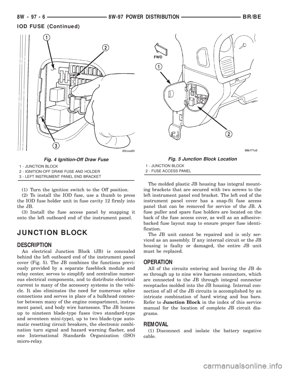
(1) Turn the ignition switch to the Off position.
(2) To install the IOD fuse, use a thumb to press
the IOD fuse holder unit in fuse cavity 12 firmly into
the JB.
(3) Install the fuse access panel by snapping it
onto the left outboard end of the instrument panel.
JUNCTION BLOCK
DESCRIPTION
An electrical Junction Block (JB) is concealed
behind the left outboard end of the instrument panel
cover (Fig. 5). The JB combines the functions previ-
ously provided by a separate fuseblock module and
relay center, serves to simplify and centralize numer-
ous electrical components, and to distribute electrical
current to many of the accessory systems in the vehi-
cle. It also eliminates the need for numerous splice
connections and serves in place of a bulkhead connec-
tor between many of the engine compartment, instru-
ment panel, and body wire harnesses. The JB houses
up to nineteen blade-type fuses (two standard-type
and seventeen mini-type), up to two blade-type auto-
matic resetting circuit breakers, the electronic combi-
nation turn signal and hazard warning flasher, and
one International Standards Organization (ISO)
micro-relay.The molded plastic JB housing has integral mount-
ing brackets that are secured with two screws to the
left instrument panel end bracket. The left end of the
instrument panel cover has a snap-fit fuse access
panel that can be removed for service of the JB. A
fuse puller and spare fuse holders are located on the
back of the fuse access cover, as well as an adhesive-
backed fuse layout map to ensure proper fuse identi-
fication.
The JB unit cannot be repaired and is only ser-
viced as an assembly. If any internal circuit or the JB
housing is faulty or damaged, the entire JB unit
must be replaced.
OPERATION
All of the circuits entering and leaving the JB do
so through up to nine wire harness connectors, which
are connected to the JB through integral connector
receptacles molded into the JB housing. Internal con-
nection of all of the JB circuits is accomplished by an
intricate combination of hard wiring and bus bars.
Refer toJunction Blockin the index of this service
manual for the location of complete JB circuit dia-
grams.
REMOVAL
(1) Disconnect and isolate the battery negative
cable.
Fig. 4 Ignition-Off Draw Fuse
1 - JUNCTION BLOCK
2 - IGNITION-OFF DRAW FUSE AND HOLDER
3 - LEFT INSTRUMENT PANEL END BRACKET
Fig. 5 Junction Block Location
1 - JUNCTION BLOCK
2 - FUSE ACCESS PANEL
8W - 97 - 6 8W-97 POWER DISTRIBUTIONBR/BE
IOD FUSE (Continued)
Page 1391 of 2889
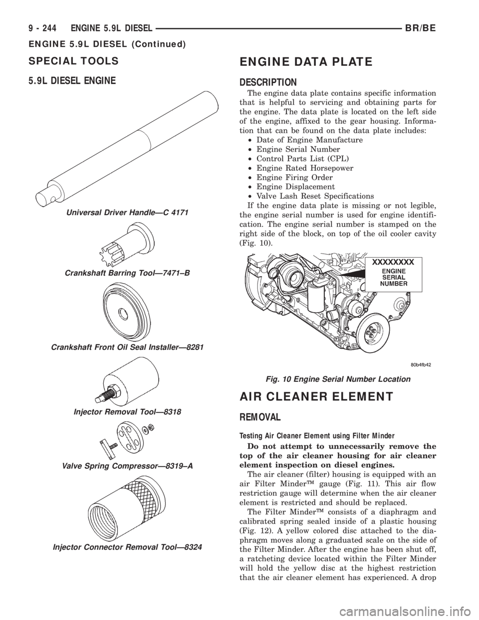
SPECIAL TOOLS
5.9L DIESEL ENGINEENGINE DATA PLATE
DESCRIPTION
The engine data plate contains specific information
that is helpful to servicing and obtaining parts for
the engine. The data plate is located on the left side
of the engine, affixed to the gear housing. Informa-
tion that can be found on the data plate includes:
²Date of Engine Manufacture
²Engine Serial Number
²Control Parts List (CPL)
²Engine Rated Horsepower
²Engine Firing Order
²Engine Displacement
²Valve Lash Reset Specifications
If the engine data plate is missing or not legible,
the engine serial number is used for engine identifi-
cation. The engine serial number is stamped on the
right side of the block, on top of the oil cooler cavity
(Fig. 10).
AIR CLEANER ELEMENT
REMOVAL
Testing Air Cleaner Element using Filter Minder
Do not attempt to unnecessarily remove the
top of the air cleaner housing for air cleaner
element inspection on diesel engines.
The air cleaner (filter) housing is equipped with an
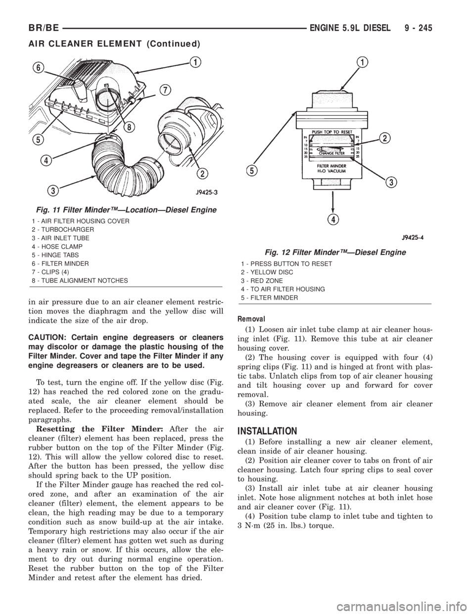
air Filter MinderŸ gauge (Fig. 11). This air flow
restriction gauge will determine when the air cleaner
element is restricted and should be replaced.
The Filter MinderŸ consists of a diaphragm and
calibrated spring sealed inside of a plastic housing
(Fig. 12). A yellow colored disc attached to the dia-
phragm moves along a graduated scale on the side of
the Filter Minder. After the engine has been shut off,
a ratcheting device located within the Filter Minder
will hold the yellow disc at the highest restriction
that the air cleaner element has experienced. A drop
Universal Driver HandleÐC 4171
Crankshaft Barring ToolÐ7471±B
Crankshaft Front Oil Seal InstallerÐ8281
Injector Removal ToolÐ8318
Valve Spring CompressorÐ8319±A
Injector Connector Removal ToolÐ8324
Fig. 10 Engine Serial Number Location
9 - 244 ENGINE 5.9L DIESELBR/BE
ENGINE 5.9L DIESEL (Continued)
Page 1392 of 2889
in air pressure due to an air cleaner element restric-
tion moves the diaphragm and the yellow disc will
indicate the size of the air drop.
CAUTION: Certain engine degreasers or cleaners
may discolor or damage the plastic housing of the
Filter Minder. Cover and tape the Filter Minder if any
engine degreasers or cleaners are to be used.
To test, turn the engine off. If the yellow disc (Fig.
12) has reached the red colored zone on the gradu-
ated scale, the air cleaner element should be
replaced. Refer to the proceeding removal/installation
paragraphs.
Resetting the Filter Minder:After the air
cleaner (filter) element has been replaced, press the
rubber button on the top of the Filter Minder (Fig.
12). This will allow the yellow colored disc to reset.
After the button has been pressed, the yellow disc
should spring back to the UP position.
If the Filter Minder gauge has reached the red col-
ored zone, and after an examination of the air
cleaner (filter) element, the element appears to be
clean, the high reading may be due to a temporary
condition such as snow build-up at the air intake.
Temporary high restrictions may also occur if the air
cleaner (filter) element has gotten wet such as during
a heavy rain or snow. If this occurs, allow the ele-
ment to dry out during normal engine operation.
Reset the rubber button on the top of the Filter
Minder and retest after the element has dried.Removal
(1) Loosen air inlet tube clamp at air cleaner hous-
ing inlet (Fig. 11). Remove this tube at air cleaner
housing cover.
(2) The housing cover is equipped with four (4)
spring clips (Fig. 11) and is hinged at front with plas-
tic tabs. Unlatch clips from top of air cleaner housing
and tilt housing cover up and forward for cover
removal.
(3) Remove air cleaner element from air cleaner
housing.
INSTALLATION
(1) Before installing a new air cleaner element,
clean inside of air cleaner housing.
(2) Position air cleaner cover to tabs on front of air
cleaner housing. Latch four spring clips to seal cover
to housing.
(3) Install air inlet tube at air cleaner housing
inlet. Note hose alignment notches at both inlet hose
and air cleaner cover (Fig. 11).
(4) Position tube clamp to inlet tube and tighten to
3 N´m (25 in. lbs.) torque.
Fig. 11 Filter MinderŸÐLocationÐDiesel Engine
1 - AIR FILTER HOUSING COVER
2 - TURBOCHARGER
3 - AIR INLET TUBE
4 - HOSE CLAMP
5 - HINGE TABS
6 - FILTER MINDER
7 - CLIPS (4)
8 - TUBE ALIGNMENT NOTCHES
Fig. 12 Filter MinderŸÐDiesel Engine
1 - PRESS BUTTON TO RESET
2 - YELLOW DISC
3 - RED ZONE
4 - TO AIR FILTER HOUSING
5 - FILTER MINDER
BR/BEENGINE 5.9L DIESEL 9 - 245
AIR CLEANER ELEMENT (Continued)
Page 1404 of 2889
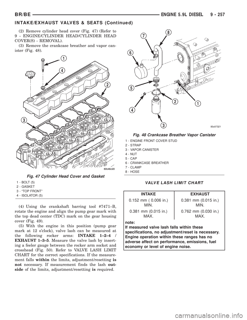
(2) Remove cylinder head cover (Fig. 47) (Refer to
9 - ENGINE/CYLINDER HEAD/CYLINDER HEAD
COVER(S) - REMOVAL).
(3) Remove the crankcase breather and vapor can-
ister (Fig. 48).
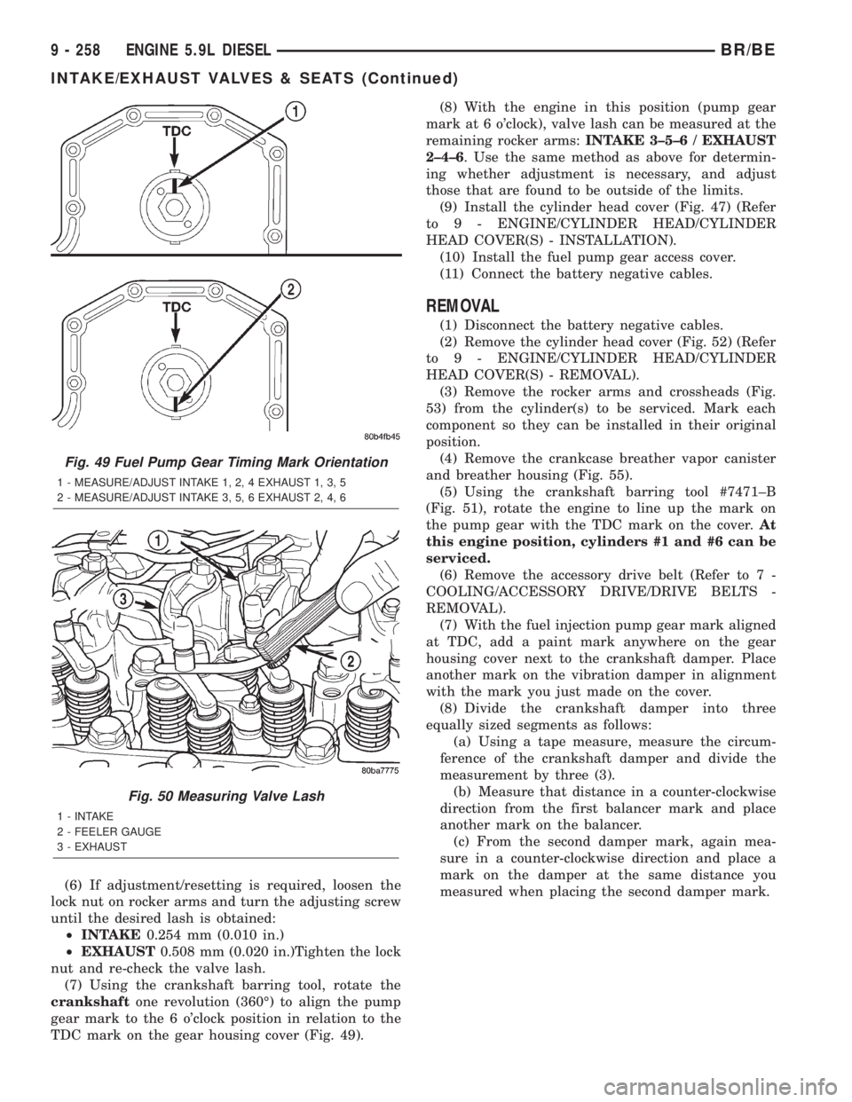
(4) Using the crankshaft barring tool #7471±B,
rotate the engine and align the pump gear mark with
the top dead center (TDC) mark on the gear housing
cover (Fig. 49).
(5) With the engine in this position (pump gear
mark at 12 o'clock), valve lash can be measured at
the following rocker arms:INTAKE 1±2±4 /
EXHAUST 1±3±5. Measure the valve lash by insert-
ing a feeler gauge between the rocker arm socket and
crosshead (Fig. 50). Refer to VALVE LASH LIMIT
CHART for the correct specifications. If the measure-
ment fallswithinthe limits, adjustment/resettingis
notnecessary. If measurement finds the lashout-
sideof the limits, adjustment/resettingisrequired.
VALVE LASH LIMIT CHART
INTAKE EXHAUST
0.152 mm ( 0.006 in.)
MIN.0.381 mm (0.015 in.)
MIN.
0.381 mm (0.015 in.)
MAX.0.762 mm (0.030 in.)
MAX.
note:
If measured valve lash falls within these
specifications, no adjustment/reset is necessary.
Engine operation within these ranges has no
adverse affect on performance, emissions, fuel
economy or level of engine noise.
Fig. 47 Cylinder Head Cover and Gasket
1 - BOLT (5)
2 - GASKET
3 - ªTOP FRONTº
4 - ISOLATOR (5)
Fig. 48 Crankcase Breather Vapor Canister
1 - ENGINE FRONT COVER STUD
2 - STRAP
3 - VAPOR CANISTER
4 - NUT
5 - CAP
6 - CRANKCASE BREATHER
7 - CLAMP
8 - HOSE
BR/BEENGINE 5.9L DIESEL 9 - 257
INTAKE/EXHAUST VALVES & SEATS (Continued)
Page 1405 of 2889
(6) If adjustment/resetting is required, loosen the
lock nut on rocker arms and turn the adjusting screw
until the desired lash is obtained:
²INTAKE0.254 mm (0.010 in.)
²EXHAUST0.508 mm (0.020 in.)Tighten the lock
nut and re-check the valve lash.
(7) Using the crankshaft barring tool, rotate the
crankshaftone revolution (360É) to align the pump
gear mark to the 6 o'clock position in relation to the
TDC mark on the gear housing cover (Fig. 49).(8) With the engine in this position (pump gear
mark at 6 o'clock), valve lash can be measured at the
remaining rocker arms:INTAKE 3±5±6 / EXHAUST
2±4±6. Use the same method as above for determin-
ing whether adjustment is necessary, and adjust
those that are found to be outside of the limits.
(9) Install the cylinder head cover (Fig. 47) (Refer
to 9 - ENGINE/CYLINDER HEAD/CYLINDER
HEAD COVER(S) - INSTALLATION).
(10) Install the fuel pump gear access cover.
(11) Connect the battery negative cables.
REMOVAL
(1) Disconnect the battery negative cables.
(2) Remove the cylinder head cover (Fig. 52) (Refer
to 9 - ENGINE/CYLINDER HEAD/CYLINDER
HEAD COVER(S) - REMOVAL).
(3) Remove the rocker arms and crossheads (Fig.
53) from the cylinder(s) to be serviced. Mark each
component so they can be installed in their original
position.
(4) Remove the crankcase breather vapor canister
and breather housing (Fig. 55).
(5) Using the crankshaft barring tool #7471±B
(Fig. 51), rotate the engine to line up the mark on
the pump gear with the TDC mark on the cover.At
this engine position, cylinders #1 and #6 can be
serviced.
(6) Remove the accessory drive belt (Refer to 7 -
COOLING/ACCESSORY DRIVE/DRIVE BELTS -
REMOVAL).
(7) With the fuel injection pump gear mark aligned
at TDC, add a paint mark anywhere on the gear
housing cover next to the crankshaft damper. Place
another mark on the vibration damper in alignment
with the mark you just made on the cover.
(8) Divide the crankshaft damper into three
equally sized segments as follows:
(a) Using a tape measure, measure the circum-
ference of the crankshaft damper and divide the
measurement by three (3).
(b) Measure that distance in a counter-clockwise
direction from the first balancer mark and place
another mark on the balancer.
(c) From the second damper mark, again mea-
sure in a counter-clockwise direction and place a
mark on the damper at the same distance you
measured when placing the second damper mark.
Fig. 49 Fuel Pump Gear Timing Mark Orientation
1 - MEASURE/ADJUST INTAKE 1, 2, 4 EXHAUST 1, 3, 5
2 - MEASURE/ADJUST INTAKE 3, 5, 6 EXHAUST 2, 4, 6
Fig. 50 Measuring Valve Lash
1 - INTAKE
2 - FEELER GAUGE
3 - EXHAUST
9 - 258 ENGINE 5.9L DIESELBR/BE
INTAKE/EXHAUST VALVES & SEATS (Continued)
Page 2737 of 2889
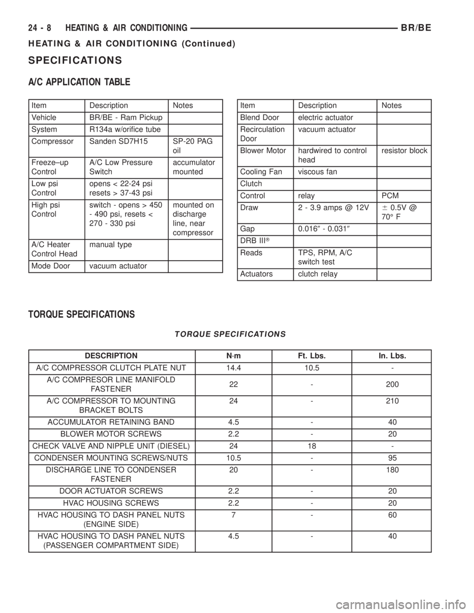
SPECIFICATIONS
A/C APPLICATION TABLE
Item Description Notes
Vehicle BR/BE - Ram Pickup
System R134a w/orifice tube
Compressor Sanden SD7H15 SP-20 PAG
oil
Freeze±up
ControlA/C Low Pressure
Switchaccumulator
mounted
Low psi
Controlopens < 22-24 psi
resets > 37-43 psi
High psi
Controlswitch - opens > 450
- 490 psi, resets <
270 - 330 psimounted on
discharge
line, near
compressor
A/C Heater
Control Headmanual type
Mode Door vacuum actuatorItem Description Notes
Blend Door electric actuator
Recirculation
Doorvacuum actuator
Blower Motor hardwired to control
headresistor block
Cooling Fan viscous fan
Clutch
Control relay PCM
Draw 2 - 3.9 amps @ 12V60.5V @
70É F
Gap 0.0169- 0.0319
DRB IIIT
Reads TPS, RPM, A/C
switch test
Actuators clutch relay
TORQUE SPECIFICATIONS
TORQUE SPECIFICATIONS
DESCRIPTION N´m Ft. Lbs. In. Lbs.
A/C COMPRESSOR CLUTCH PLATE NUT 14.4 10.5 -
A/C COMPRESOR LINE MANIFOLD
FASTENER22 - 200
A/C COMPRESSOR TO MOUNTING
BRACKET BOLTS24 - 210
ACCUMULATOR RETAINING BAND 4.5 - 40
BLOWER MOTOR SCREWS 2.2 - 20
CHECK VALVE AND NIPPLE UNIT (DIESEL) 24 18 -
CONDENSER MOUNTING SCREWS/NUTS 10.5 - 95
DISCHARGE LINE TO CONDENSER
FASTENER20 - 180
DOOR ACTUATOR SCREWS 2.2 - 20
HVAC HOUSING SCREWS 2.2 - 20
HVAC HOUSING TO DASH PANEL NUTS
(ENGINE SIDE)7-60
HVAC HOUSING TO DASH PANEL NUTS
(PASSENGER COMPARTMENT SIDE)4.5 - 40
24 - 8 HEATING & AIR CONDITIONINGBR/BE
HEATING & AIR CONDITIONING (Continued)
Page 2828 of 2889
Items found requiring adjustment and/or repair
should be corrected before delivery of the vehicle.
NOTE: It is the dealer's responsibility to protect
new vehicles from damage and deterioration prior
to retail delivery both before and after new vehicle
preparation.
The information includes the following features:
Inspection points are cross-referenced to the New
Vehicle Preparation Form as follows:
²Titles indicate the general area being inspected
or the types of checks being made (i.e., underhood,
body-exterior, road test, etc.).
²Sub-Titles identify the types of items to be
inspected in that area (i.e., lines/hoses, wiring, etc.).
Procedures follow a logical order to prevent dupli-
cation and wasted effort.
Tips to help you do a better job are found as
NOTES.
RECEIVING
INSPECTION
The following procedures are recommended for
your own protection upon receipt of new vehicles.
When a new car is delivered by the carrier, it should
be inspected to ensure that it is in good condition
and to determine if there is any shortage or transpor-
tation damage.
EXTERIOR
Upon receipt of a new vehicle, check immediately
for:
²Under carriage damage
²Chipped or cracked windshield, broken windows,
and loose or missing moldings and name-plates
²Dents, scrapes, scratches, chips, dirt in paints or
other damage to the body exterior
²Damaged or missing side view mirror(s)
²Missing wheel nuts
²Broken or missing lenses
²Chafing, bruises, cuts, or scrapes on tire side-
walls or tread
²Missing underhood items
²Missing fuel filler cap
²Shipped loose items-license plate bracket, spare
tire, jack and tire wrench, radio antenna, floor mats,
wheel covers, cargo nets, fuses and other items²Ensure that IOD fuse is removed
²Check battery test indicator when easily visible,
or use voltmeter (battery must be at 12.4 volts or
greater). Charge to ensure green dot-visibility, per-
manent damage may occur if battery remains in a
discharged state for any length of time.
INTERIOR
Check interior items such as:
²Rearview mirror
²Accessory control knobs
²Smokers package items
²Keys
²Radio
²Special equipment items listed on shipper
²Owner's Manual and Consumer information Bro-
chures (normally stored in the glove box).
²Cuts, abrasions or stains on interior trim.
NOTE: Remember a careful look at new vehicles
when they are received may prevent problems when
preparing vehicles for delivery to your customers.
MAJOR INSPECTION POINTS
(1) Check operation of hood latch and safety catch-
adjust as required.
(2) Check all fluids for proper level and top off
with the proper fluid as required-engine oil, auto-
matic transmission fluid, brake master cylinder,
clutch master cylinder, power steering, windshield
washer, and cooling system. (Vehicle must be at nor-
mal operating temperature for some of these checks.)
(3) Check brake, clutch, fuel, and power steering
lines and hoses for leaks and clearance from moving
and hot objects-reroute to the proper location and
tighten as required.
(4) Check battery state of charge-recharge if neces-
sary, to ensure green dot is visible or instrument
panel voltmeter indicates 12.4 volts or greater.
(5) Check routing and connections of underhood
wiring, vacuum hoses, refrigerant lines and coolant
hoses for leaks, loose connections and clearance from
moving objects reroute and tighten connections as
required. Install IOD fuse on applicable vehicles.
NOTE: Reset radio, clock, compass, etc., after
installing, if vehicle is being delivered.
BR/BENEW VEHICLE PREPARATION 30 - 3
INTRODUCTION (Continued)