2001 DODGE RAM reset
[x] Cancel search: resetPage 668 of 2889
PASSENGER POWER SEAT
SWITCH
DESCRIPTION
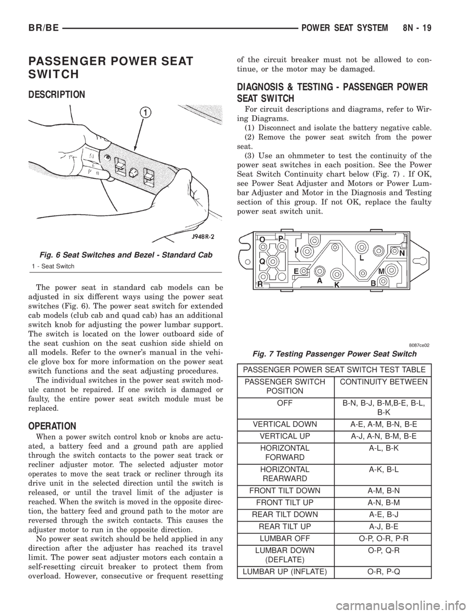
The power seat in standard cab models can be
adjusted in six different ways using the power seat
switches (Fig. 6). The power seat switch for extended
cab models (club cab and quad cab) has an additional
switch knob for adjusting the power lumbar support.
The switch is located on the lower outboard side of
the seat cushion on the seat cushion side shield on
all models. Refer to the owner's manual in the vehi-
cle glove box for more information on the power seat
switch functions and the seat adjusting procedures.
The individual switches in the power seat switch mod-
ule cannot be repaired. If one switch is damaged or
faulty, the entire power seat switch module must be
replaced.
OPERATION
When a power switch control knob or knobs are actu-
ated, a battery feed and a ground path are applied
through the switch contacts to the power seat track or
recliner adjuster motor. The selected adjuster motor
operates to move the seat track or recliner through its
drive unit in the selected direction until the switch is
released, or until the travel limit of the adjuster is
reached. When the switch is moved in the opposite direc-
tion, the battery feed and ground path to the motor are
reversed through the switch contacts. This causes the
adjuster motor to run in the opposite direction.
No power seat switch should be held applied in any
direction after the adjuster has reached its travel
limit. The power seat adjuster motors each contain a
self-resetting circuit breaker to protect them from
overload. However, consecutive or frequent resettingof the circuit breaker must not be allowed to con-
tinue, or the motor may be damaged.
DIAGNOSIS & TESTING - PASSENGER POWER
SEAT SWITCH
For circuit descriptions and diagrams, refer to Wir-
ing Diagrams.
(1)
Disconnect and isolate the battery negative cable.
(2)Remove the power seat switch from the power
seat.
(3) Use an ohmmeter to test the continuity of the
power seat switches in each position. See the Power
Seat Switch Continuity chart below (Fig. 7) . If OK,
see Power Seat Adjuster and Motors or Power Lum-
bar Adjuster and Motor in the Diagnosis and Testing
section of this group. If not OK, replace the faulty
power seat switch unit.
PASSENGER POWER SEAT SWITCH TEST TABLE
PASSENGER SWITCH
POSITIONCONTINUITY BETWEEN
OFF B-N, B-J, B-M,B-E, B-L,
B-K
VERTICAL DOWN A-E, A-M, B-N, B-E
VERTICAL UP A-J, A-N, B-M, B-E
HORIZONTAL
FORWARDA-L, B-K
HORIZONTAL
REARWARDA-K, B-L
FRONT TILT DOWN A-M, B-N
FRONT TILT UP A-N, B-M
REAR TILT DOWN A-E, B-J
REAR TILT UP A-J, B-E
LUMBAR OFF O-P, O-R, P-R
LUMBAR DOWN
(DEFLATE)O-P, Q-R
LUMBAR UP (INFLATE) O-R, P-Q
Fig. 6 Seat Switches and Bezel - Standard Cab
1 - Seat Switch
Fig. 7 Testing Passenger Power Seat Switch
BR/BEPOWER SEAT SYSTEM 8N - 19
Page 670 of 2889
the motor and drive unit of the power seat recliner
mechanism is secured with two screws to the seat
cushion frame, and is concealed by the outboard seat
cushion side shield.
The power seat recliner cannot be repaired. If the
unit is faulty or damaged, it must be replaced. Refer
toBucket Seat Reclinerin Body for the service
procedure.
OPERATION
The power seat recliner includes a reversible elec-
tric motor that is secured to the lower hinge plate of
the recliner unit. The motor is connected to a gearbox
that moves the upper hinge plate of the power seat
recliner through a screw-type drive unit.
DIAGNOSIS & TESTING - POWER SEAT
RECLINER
Following are tests that will help to diagnose the
hard wired components and circuits of the power seat
system. Actuate the power seat recliner switch to
move the power seat recliner adjuster in each direc-
tion. The power seat recliner adjuster should move in
both directions. If the power seat recliner adjuster
fails to operate in only one direction, move the
adjuster a short distance in the opposite direction
and test again to be certain that the adjuster is not
at its travel limit. If the power seat recliner adjuster
still fails to operate in only one direction, refer to
Power Seat Switchin the Diagnosis and Testing
section of this group. If the power recliner adjuster
fails to operate in either direction, perform the fol-
lowing tests. For complete circuit diagrams, refer to
Power Seatin Wiring Diagrams.
(1) Check the power seat circuit breaker in the
junction block. If OK, go to Step 2. If not OK, replace
the faulty power seat circuit breaker.
(2) Check for battery voltage at the power seat cir-
cuit breaker in the junction block. If OK, go to Step
3. If not OK, repair the open fused B(+) circuit to the
fuse in the Power Distribution Center as required.
(3) Remove the outboard seat cushion side shield
from the seat. Disconnect the seat wire harness con-
nector from the power seat switch connector recepta-
cle. Check for battery voltage at the fused B(+)
circuit cavity of the power seat wire harness connec-
tor for the power seat switch. If OK, go to Step 4. If
not OK, repair the open fused B(+) circuit to the
power seat circuit breaker in the junction block as
required.
(4) Check for continuity between the ground cir-
cuit cavity of the power seat wire harness connector
for the power seat switch and a good ground. There
should be continuity. If OK, go to Step 5. If not OK,
repair the open ground circuit to ground as required.(5) Test the power seat switch. Refer toPower
Seat Switchin the Diagnosis and Testing section of
this group. If the switch tests OK, test the circuits of
the power seat wire harness between the power seat
recliner adjuster motor and the power seat switch for
shorts or opens. If the circuits check OK, replace the
faulty power seat recliner unit. If the circuits are not
OK, repair the power seat wire harness as required.
POWER SEAT TRACK
DESCRIPTION
There are three reversible motors that operate the
power seat adjuster. The motors are connected to
worm-drive gearboxes that move the seat adjuster
through a combination of screw-type drive units.
The front and rear of a seat are operated by differ-
ent motors. They can be raised or lowered indepen-
dently of each other. When the center seat switch is
pushed in the Up or Down direction, both the front
and rear motors operate in unison. On standard cab
models the entire seat is moved up or down, on
extended cab models (club cab and quad cab) the seat
cushion moves independently of the seat back in the
up or down directions. The forward-rearward motor
is operated by pushing the center seat switch in the
Forward or Rearward direction, which moves the
entire seat in the selected direction on all models.
Each motor contains a self-resetting circuit breaker
to protect it from overload. Consecutive or frequent
resetting of the circuit breakers must not be allowed
to continue, or the motors may be damaged. Make
the necessary repairs.
The power seat adjuster and motors cannot be
repaired, and are serviced only as a complete unit. If
any component in this unit is faulty or damaged, the
entire power seat adjuster and motors assembly must
be replaced.
OPERATION
When a power seat switch is actuated, a battery
feed and a ground path are applied through the
switch contacts to the motor(s). The motor(s) and
drive unit(s) operate to move the seat in the selected
direction until the switch is released, or until the
travel limit of the power seat adjuster is reached.
When the switch is moved in the opposite direction,
the battery feed and ground path to the motor(s) are
reversed through the switch contacts. This causes the
motor to run in the opposite direction.
DIAGNOSIS & TESTING - POWER SEAT TRACK
For circuit descriptions and diagrams, refer to Wir-
ing Diagrams.
BR/BEPOWER SEAT SYSTEM 8N - 21
RECLINER MOTOR (Continued)
Page 675 of 2889
INSTALLATION
(1) Connect the power window switch to the har-
ness connector.
(2) Insert the rear of the switch and bezel unit into
the opening.
(3) Push down on the front of the switch until the
retaining tabs snap into place.
(4) Reconnect the battery negative cable.
WINDOW MOTOR
DESCRIPTION
A permanent magnet reversible motor moves the
window regulator through an integral gearbox mech-
anism. A positive and negative battery connection to
the two motor terminals will cause the motor to
rotate in one direction. Reversing the current
through these same two connections will cause the
motor to rotate in the opposite direction.
In addition, each power window motor is equipped
with an integral self-resetting circuit breaker to pro-
tect the motor from overloads. The power window
motor and gearbox assembly cannot be repaired and,
if faulty or damaged, the entire power window regu-
lator assembly must be replaced.
DIAGNOSIS AND TESTING - WINDOW MOTOR
For circuit descriptions and diagrams, refer to the
appropriate wiring information. The wiring informa-
tion includes wiring diagrams, proper wire and con-
nector repair procedures, details of wire harness
routing and retention, connector pin-out information
and location views for the various wire harness con-
nectors, splices and grounds. Before you proceed withthis diagnosis, confirm proper switch operation.
(Refer to 8 - ELECTRICAL/POWER WINDOWS/
POWER WINDOW SWITCH - DIAGNOSIS AND
TESTING).
(1) Disconnect and isolate the battery negative
cable. Remove the trim panel from the door with the
inoperative power window.
(2) Unplug the power window motor wire harness
connector. Apply 12 volts across the motor terminals
to check its operation in one direction. Reverse the
connections across the motor terminals to check the
operation in the other direction. Remember, if the
window is in the full up or full down position, the
motor will not operate in that direction by design. If
OK, repair the circuits from the power window motor
to the power window switch as required. If not OK,
replace the faulty motor.
(3) If the motor operates in both directions, check
the operation of the window glass and lift mechanism
through its complete up and down travel. There
should be no binding or sticking of the window glass
or lift mechanism through the entire travel range. If
not OK, (Refer to 23 - BODY/DOOR - FRONT/WIN-
DOW REGULATOR - REMOVAL).
REMOVAL
The power window motor and mechanism is inte-
gral to the power window regulator unit. If the power
window motor or mechanism is faulty or damaged,
the entire power window regulator unit must be
replaced. (Refer to 23 - BODY/DOOR - FRONT/WIN-
DOW REGULATOR - REMOVAL) for the window
regulator service procedures.
8N - 26 POWER WINDOWSBR/BE
POWER WINDOW SWITCH (Continued)
Page 737 of 2889
WIPER MODULE
DESCRIPTION
The wiper module is secured with screws to the
cowl plenum panel and concealed within the cowl
plenum area beneath the cowl plenum cover/grille
panel. The ends of the wiper pivot shafts that pro-
trude through dedicated openings in the cowl plenum
cover/grille panel to drive the wiper arms and blades
are the only visible components of the wiper module.
The wiper module consists of the following major
components:
²Bracket- The wiper module bracket consists of
a long tubular steel main member that has a
stamped pivot bracket formation near each end
where the two wiper pivots are secured. A stamped
steel mounting plate for the wiper motor is secured
with welds near the center of the main member.
²Crank Arm- The wiper motor crank arm is a
stamped steel unit that has a slotted hole on the
driven end that is secured to the wiper motor output
shaft with a nut, and has a ball stud secured to the
drive end.
²Linkage- The two wiper linkage members are
each constructed of stamped steel. A driver side drive
link with a plastic socket-type bushing in the left
end, and a plastic sleeve-type bushing in the right
end. Socket bushing is snap-fit over the pivot ball
stud on the left pivot, while the sleeve bushing is fit
over the longer wiper motor crank arm pivot stud.
The passenger side drive link has a plastic socket-
type bushing on each end. One end of this drive link
is snap-fit over the pivot ball stud on the right pivot,
while the other end is snap-fit over the exposed end
of the longer ball stud on the wiper motor crank arm.
²Motor- The wiper motor is secured with three
screws to the motor mounting plate near the center
of the wiper module bracket. The wiper motor output
shaft passes through a hole in the module bracket,
where a nut secures the wiper motor crank arm to
the motor output shaft. The two-speed permanent
magnet wiper motor features an integral transmis-
sion, an internal park switch, and an internal Posi-
tive Temperature Coefficient (PTC) circuit breaker.
²Pivots- The two wiper pivots are secured to the
ends of the wiper module bracket. The crank arms
that extend from the bottom of the pivot shafts each
have a ball stud on their end. The upper end of each
pivot shaft where the wiper arms will be fastened
each has an externally serrated drum secured to it.
The wiper module cannot be adjusted or repaired.
If any component of the module is faulty or damaged,
the entire wiper module unit must be replaced.
OPERATION
The wiper module operation is controlled by the
vehicle operator through battery current inputs
received by the wiper motor from the multi-function
switch on the steering column. The wiper motor
speed is controlled by current flow to either the low
speed or the high speed set of brushes. The park
switch is a single pole, single throw, momentary
switch within the wiper motor that is mechanically
actuated by the wiper motor transmission compo-
nents. The park switch alternately closes the wiper
park switch sense circuit to ground or to battery cur-
rent, depending upon the position of the wipers on
the glass. This feature allows the motor to complete
its current wipe cycle after the wiper system has
been turned Off, and to park the wiper blades in the
lowest portion of the wipe pattern. The automatic
resetting circuit breaker protects the motor from
overloads. The wiper motor crank arm, the two wiper
linkage members, and the two wiper pivots mechan-
ically convert the rotary output of the wiper motor to
the back and forth wiping motion of the wiper arms
and blades on the glass.
REMOVAL
(1) Disconnect and isolate the battery negative
cable.
(2) Remove the wiper arms from the wiper pivots.
(Refer to 8 - ELECTRICAL/WIPERS/WASHERS/
WIPER ARMS - REMOVAL).
(3) Remove the cowl plenum cover/grille panel
from the cowl plenum. (Refer to 23 - BODY/EXTERI-
OR/COWL GRILLE - REMOVAL).
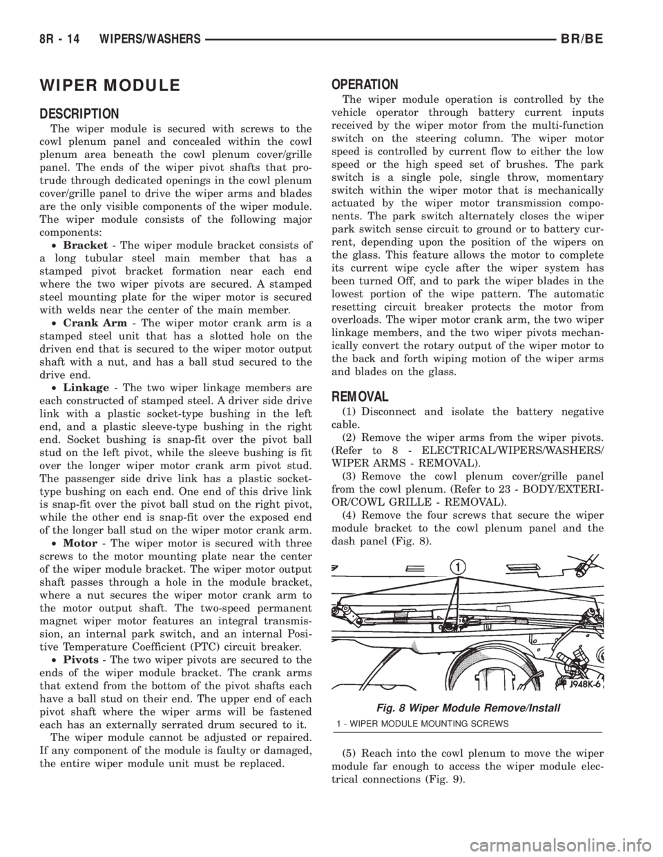
(4) Remove the four screws that secure the wiper
module bracket to the cowl plenum panel and the
dash panel (Fig. 8).
(5) Reach into the cowl plenum to move the wiper
module far enough to access the wiper module elec-
trical connections (Fig. 9).
Fig. 8 Wiper Module Remove/Install
1 - WIPER MODULE MOUNTING SCREWS
8R - 14 WIPERS/WASHERSBR/BE
Page 751 of 2889
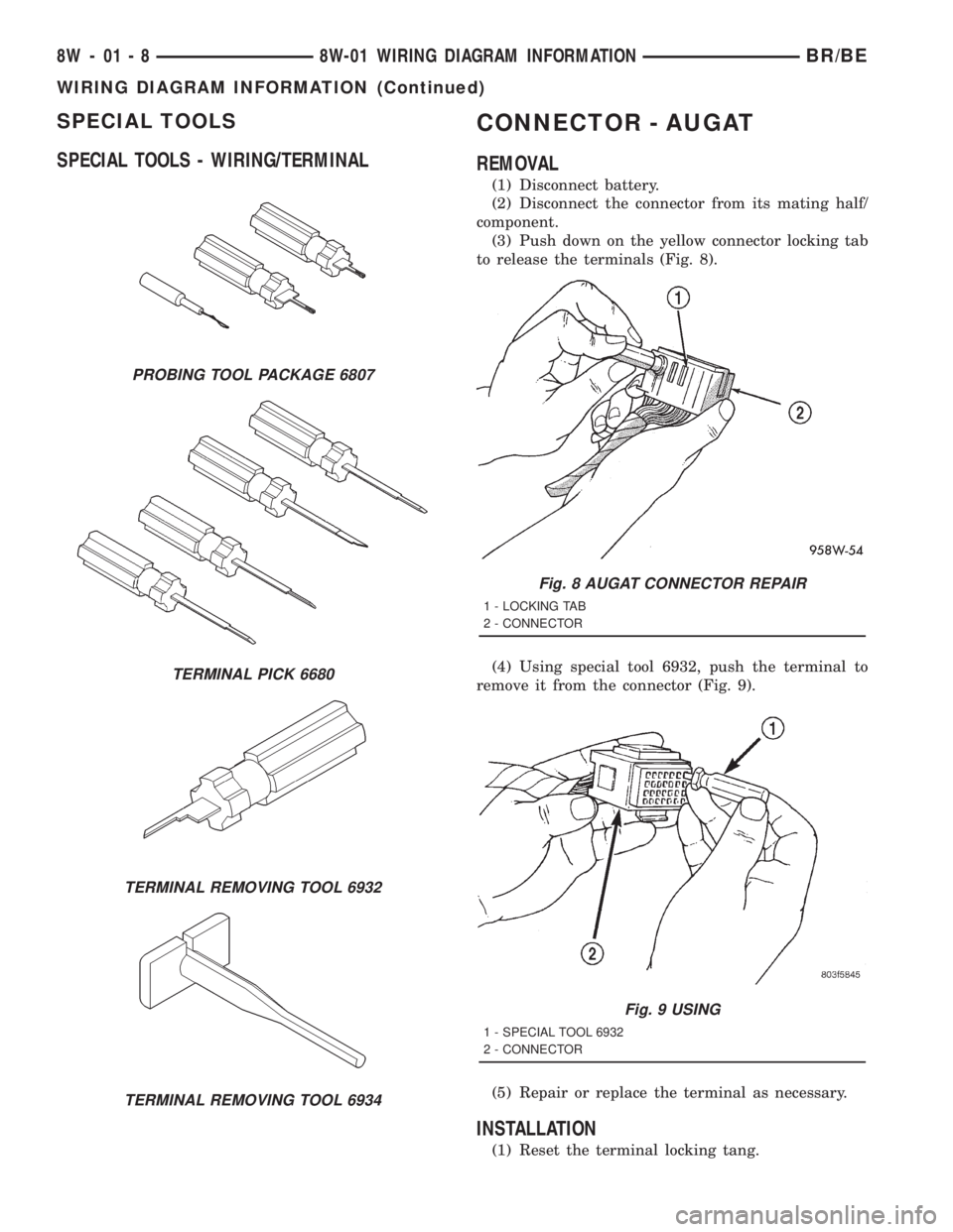
SPECIAL TOOLS
SPECIAL TOOLS - WIRING/TERMINALCONNECTOR - AUGAT
REMOVAL
(1) Disconnect battery.
(2) Disconnect the connector from its mating half/
component.
(3) Push down on the yellow connector locking tab
to release the terminals (Fig. 8).
(4) Using special tool 6932, push the terminal to
remove it from the connector (Fig. 9).
(5) Repair or replace the terminal as necessary.
INSTALLATION
(1) Reset the terminal locking tang.
PROBING TOOL PACKAGE 6807
TERMINAL PICK 6680
TERMINAL REMOVING TOOL 6932
TERMINAL REMOVING TOOL 6934
Fig. 8 AUGAT CONNECTOR REPAIR
1 - LOCKING TAB
2 - CONNECTOR
Fig. 9 USING
1 - SPECIAL TOOL 6932
2 - CONNECTOR
8W - 01 - 8 8W-01 WIRING DIAGRAM INFORMATIONBR/BE
WIRING DIAGRAM INFORMATION (Continued)
Page 752 of 2889
(2) Insert the removed wire in the same cavity on
the repair connector.
(3) Repeat steps for each wire in the connector,
being sure that all wires are inserted into the proper
cavities. For additional connector pin-out identifica-
tion, refer to the wiring diagrams.
(4) When the connector is re-assembled, the lock-
ing tab must be placed in the locked position to pre-
vent terminal push out.
(5) Connect connector to its mating half/compo-
nent.
(6) Connect battery and test all affected systems.
CONNECTOR - MOLEX
REMOVAL
(1) Disconnect battery.
(2) Disconnect the connector from its mating half/
component.
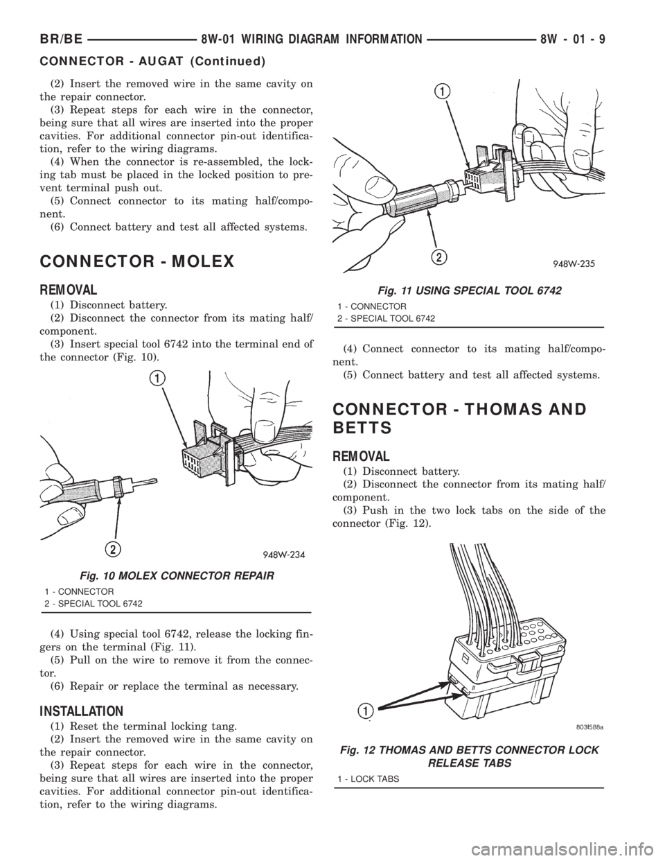
(3) Insert special tool 6742 into the terminal end of
the connector (Fig. 10).
(4) Using special tool 6742, release the locking fin-
gers on the terminal (Fig. 11).
(5) Pull on the wire to remove it from the connec-
tor.
(6) Repair or replace the terminal as necessary.
INSTALLATION
(1) Reset the terminal locking tang.
(2) Insert the removed wire in the same cavity on
the repair connector.
(3) Repeat steps for each wire in the connector,
being sure that all wires are inserted into the proper
cavities. For additional connector pin-out identifica-
tion, refer to the wiring diagrams.(4) Connect connector to its mating half/compo-
nent.
(5) Connect battery and test all affected systems.
CONNECTOR - THOMAS AND
BETTS
REMOVAL
(1) Disconnect battery.
(2) Disconnect the connector from its mating half/
component.
(3) Push in the two lock tabs on the side of the
connector (Fig. 12).
Fig. 10 MOLEX CONNECTOR REPAIR
1 - CONNECTOR
2 - SPECIAL TOOL 6742
Fig. 11 USING SPECIAL TOOL 6742
1 - CONNECTOR
2 - SPECIAL TOOL 6742
Fig. 12 THOMAS AND BETTS CONNECTOR LOCK
RELEASE TABS
1 - LOCK TABS
BR/BE8W-01 WIRING DIAGRAM INFORMATION 8W - 01 - 9
CONNECTOR - AUGAT (Continued)
Page 753 of 2889
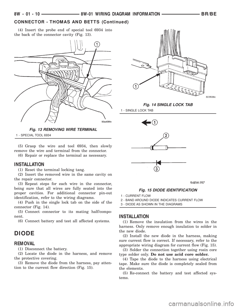
(4) Insert the probe end of special tool 6934 into
the back of the connector cavity (Fig. 13).
(5) Grasp the wire and tool 6934, then slowly
remove the wire and terminal from the connector.
(6) Repair or replace the terminal as necessary.
INSTALLATION
(1) Reset the terminal locking tang.
(2) Insert the removed wire in the same cavity on
the repair connector.
(3) Repeat steps for each wire in the connector,
being sure that all wires are fully seated into the
proper cavities. For additional connector pin-out
identification, refer to the wiring diagrams.
(4) Push in the single lock tab on the side of the
connector (Fig. 14).
(5) Connect connector to its mating half/compo-
nent.
(6) Connect battery and test all affected systems.
DIODE
REMOVAL
(1) Disconnect the battery.
(2) Locate the diode in the harness, and remove
the protective covering.
(3) Remove the diode from the harness, pay atten-
tion to the current flow direction (Fig. 15).
INSTALLATION
(1) Remove the insulation from the wires in the
harness. Only remove enough insulation to solder in
the new diode.
(2) Install the new diode in the harness, making
sure current flow is correct. If necessary, refer to the
appropriate wiring diagram for current flow (Fig. 15).
(3) Solder the connection together using rosin core
type solder only.Do not use acid core solder.
(4) Tape the diode to the harness using electrical
tape. Make sure the diode is completely sealed from
the elements.
(5) Re-connect the battery and test affected sys-
tems.
Fig. 13 REMOVING WIRE TERMINAL
1 - SPECIAL TOOL 6934
Fig. 14 SINGLE LOCK TAB
1 - SINGLE LOCK TAB
Fig. 15 DIODE IDENTIFICATION
1 - CURRENT FLOW
2 - BAND AROUND DIODE INDICATES CURRENT FLOW
3 - DIODE AS SHOWN IN THE DIAGRAMS
8W - 01 - 10 8W-01 WIRING DIAGRAM INFORMATIONBR/BE
CONNECTOR - THOMAS AND BETTS (Continued)
Page 1136 of 2889
8W-97 POWER DISTRIBUTION
TABLE OF CONTENTS
page page
POWER DISTRIBUTION
DESCRIPTION............................1
OPERATION.............................1
SPECIAL TOOLS..........................2
CIGAR LIGHTER OUTLET
DESCRIPTION............................2
OPERATION.............................2
DIAGNOSIS AND TESTING..................2
CIGAR LIGHTER........................2
REMOVAL...............................3
INSTALLATION............................3
CIRCUIT BREAKER
DESCRIPTION............................4
DIAGNOSIS AND TESTING..................4
CIRCUIT BREAKER......................4
GENERATOR CARTRIDGE FUSE
DESCRIPTION............................4
OPERATION.............................4
REMOVAL...............................4
INSTALLATION............................4
IOD FUSE
DESCRIPTION............................4OPERATION.............................5
REMOVAL...............................5
INSTALLATION............................5
JUNCTION BLOCK
DESCRIPTION............................6
OPERATION.............................6
REMOVAL...............................6
INSTALLATION............................7
POWER DISTRIBUTION CENTER
DESCRIPTION............................7
OPERATION.............................8
REMOVAL...............................8
INSTALLATION............................8
POWER OUTLET
DESCRIPTION............................9
OPERATION.............................10
DIAGNOSIS AND TESTING.................10
POWER OUTLET.......................10
REMOVAL..............................10
INSTALLATION...........................11
POWER DISTRIBUTION
DESCRIPTION
This group covers the various standard and
optional power distribution components used on this
model. The power distribution system for this vehicle
consists of the following components:
²Power Distribution Center (PDC)
²Junction Block (JB).
The power distribution system also incorporates
various types of circuit control and protection fea-
tures, including:
²Automatic resetting circuit breakers
²Blade-type fuses
²Cartridge fuses
²Circuit splice blocks
²Flashers
²Relays.
Following are general descriptions of the major
components in the power distribution system. See the
owner's manual in the vehicle glove box for more
information on the features and use of all of thepower distribution system components. Refer to the
index in this service manual for the location of com-
plete circuit diagrams for the various power distribu-
tion system components.
OPERATION
The power distribution system for this vehicle is
designed to provide safe, reliable, and centralized dis-
tribution points for the electrical current required to
operate all of the many standard and optional facto-
ry-installed electrical and electronic powertrain,
chassis, safety, security, comfort and convenience sys-
tems. At the same time, the power distribution sys-
tem was designed to provide ready access to these
electrical distribution points for the vehicle techni-
cian to use when conducting diagnosis and repair of
faulty circuits. The power distribution system can
also prove useful for the sourcing of additional elec-
trical circuits that may be required to provide the
electrical current needed to operate many accessories
that the vehicle owner may choose to have installed
in the aftermarket.
BR/BE8W-97 POWER DISTRIBUTION 8W - 97 - 1